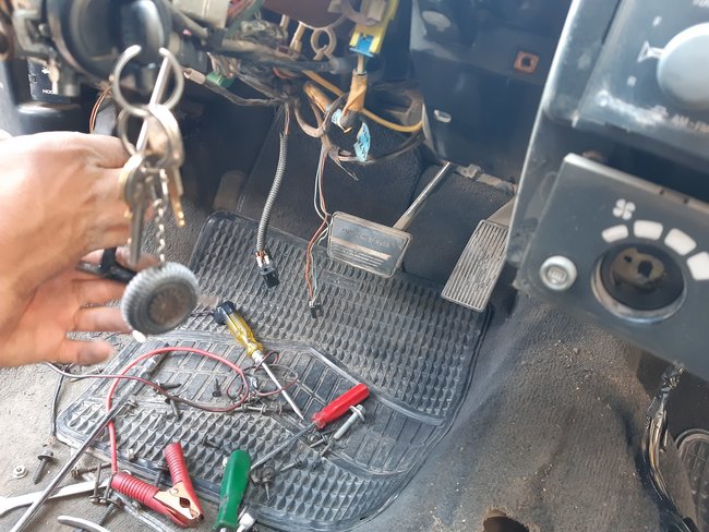
Wiring diagram for ECT sensor and sender units needed

Tiny
YASIRDAHHAM
  • MEMBER
  • 1995 PONTIAC GRAND AM
  • 2.3L
  • 4 CYL
  • 2WD
  • AUTOMATIC
  • 240,000 MILES
Dear Danny L, (and whoever has something to help me with). Weeks ago you kindly sent me a drawing for the ECT sensor and sender units. I have dismantled the part that houses both units (in addition to another anonymous sensor unit as you can see in the attached shots). Could you kindly help me finish this issue telling me what are the colors of the wires connecting both ECT sender and sensor units?
1. The ECT sensor unit (according to the schematic in the 6th attachment) should have the (black and yellow wires marked within a red rectangular frame here), right?
2. What colors refer to the wires of the ETC sender unit?
3. Where on the PCM do the sender unit wires go (in case I need to track them)?
Wednesday, July 28th, 2021 AT 8:25 AM

104 Replies

Tiny
CARADIODOC
  • MECHANIC
  • 33,727 POSTS
Here's the diagrams and list of the pins for the Engine Computer.

What kind of problem are you trying to solve? The sensor for the gauges will always have just one wire, and it goes to the instrument cluster. Sensors for the Engine Computer will always have two wires. That coolant temperature circuit normally causes very little trouble. The sensor itself is especially trouble-free because they have just one component inside them. Most problems are caused by corroded connector terminals.

A quick test of this circuit to see if it's working is to measure the voltage on the yellow wire, but that has to be done while it's plugged in. Back-probe through the weather seal next to the wire. You should find between roughly 0.5 and 4.5 volts. The higher the coolant temperature, the lower will be the voltage. If you find 5.0 volts, there's a break after that point, as in the sensor, the connector terminals, or the ground wire. Remember, the ground wire is shared with other sensors, so if it has a break, you'll have multiple diagnostic fault codes sets related to them.
Was this
answer
helpful?
Yes
No
+1
Wednesday, July 28th, 2021 AT 6:02 PM
Tiny
YASIRDAHHAM
  • MEMBER
  • 186 POSTS
Dear CARADIODOC,

These are invaluable aids as far as I am needing any clue, I am extremely grateful for that. The wires within the harness coming from the 4 relays corner all the way around the rear of the engine and then to the front side had some terminated wires as one reckless electrician was dealing with an intermittent shutting down of the engine. The engine would stall all of a sudden as I am driving or even when warming up (stationary) in the garage. I tried all possible reasons and replaced all sensors in the intake manifold (including the crank position sensor, MAP, TPS and air flow sensor as they call it here) down to the fuel pressure regulator (valve) of the fuel line rack, nozzles along with their harness, ignition switch (both the mechanical one to the right of the steering wheel and the sophisticated black one at its rear protruding from the left side of the steering wheel), I even replaced the fuel pump relay control switch/engine oil pressure switch. I dismantled the whole thick harness and checked for any short circuit or discontinuity. The remaining issue is these (ECT sensor and sender), I am differentiating between the two terms: sensor and sender as it was in earlier threads where I inquired about the wiring of the engine 2 months ago. By (sensor) I be referring to the unit that provides the readings of the temperature gauge in the ip whereas by (sender ) I be referring to the unit that provides coolant temperature info to the PCM.
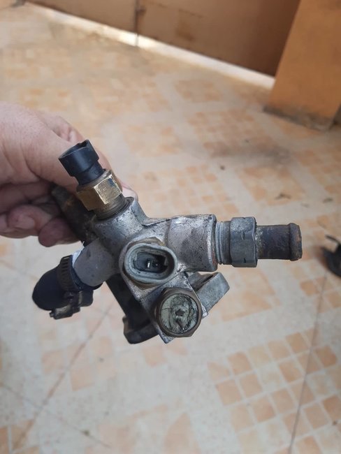
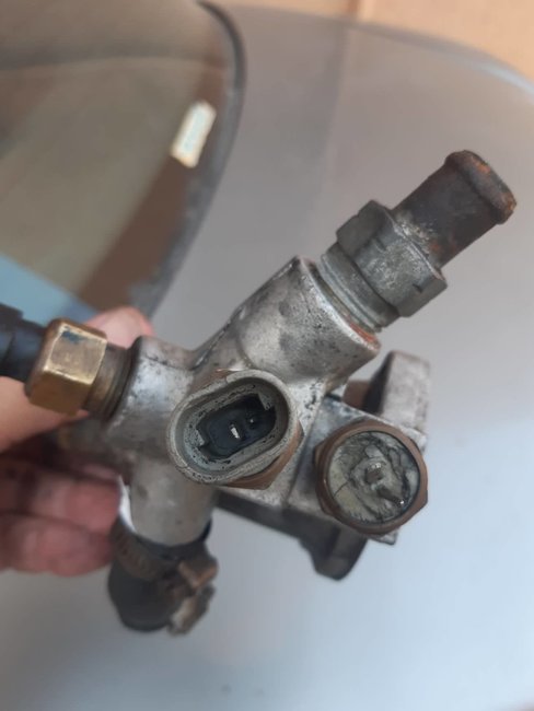
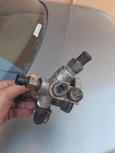
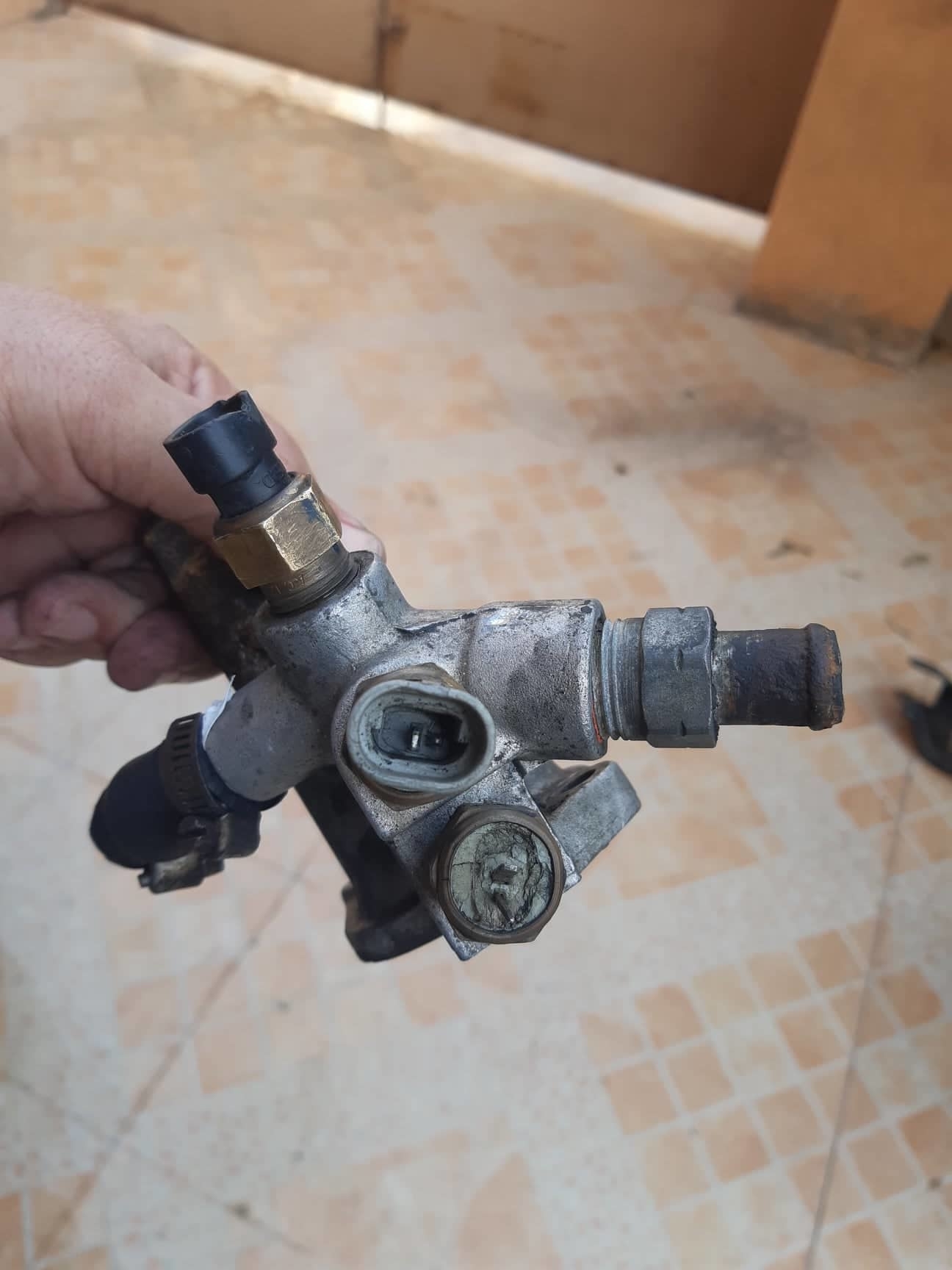
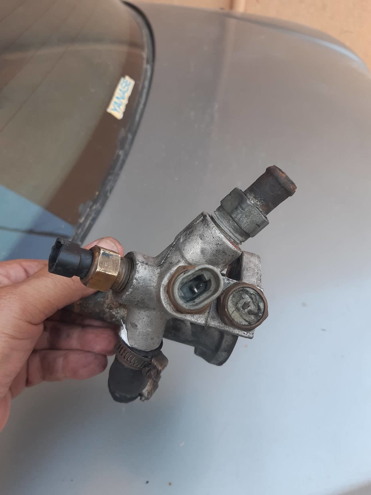
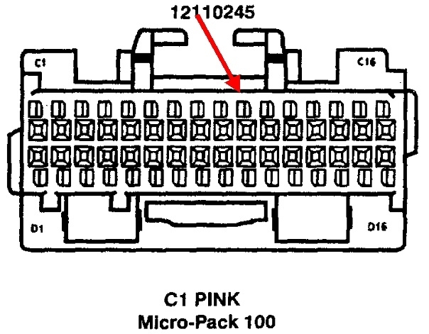
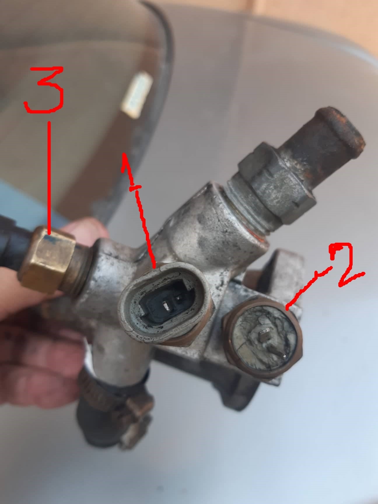
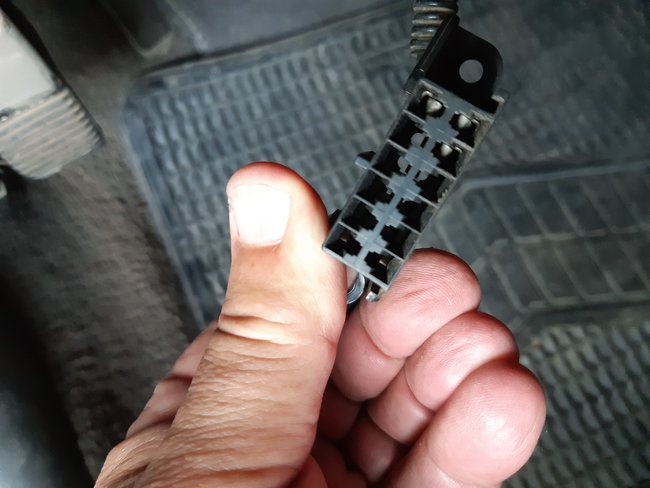
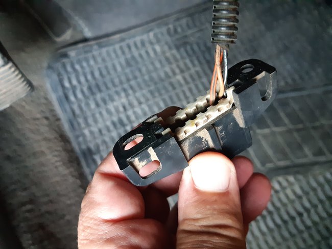
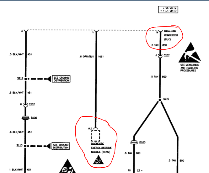
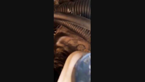
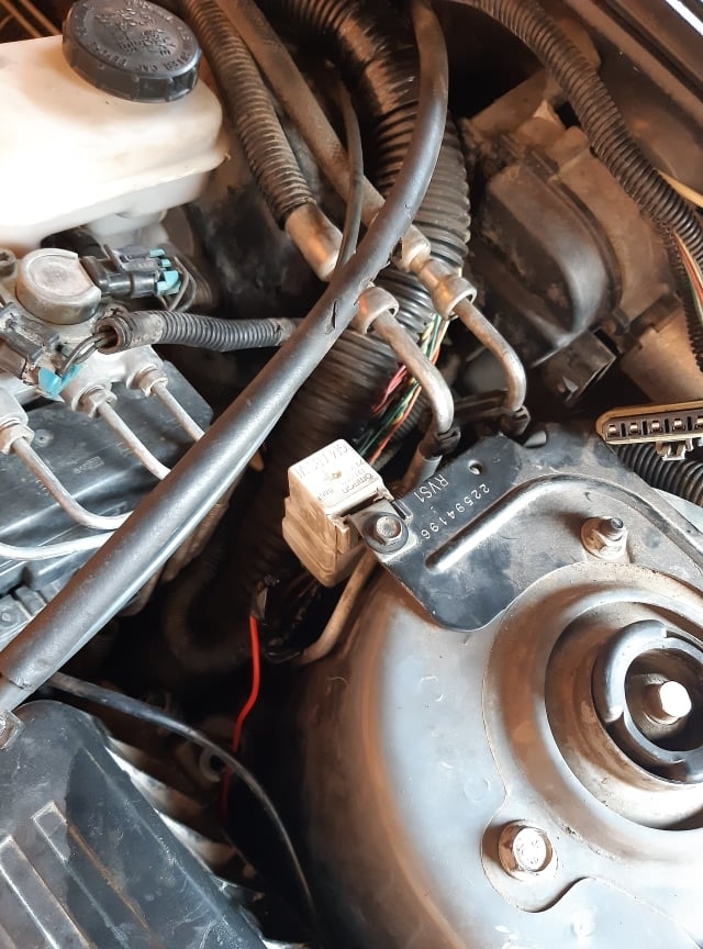
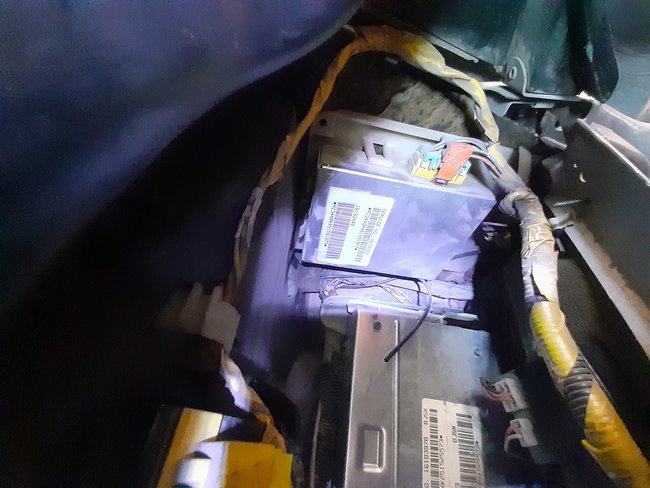
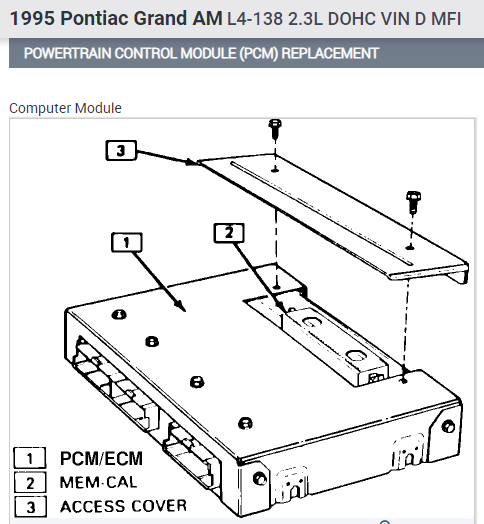
As you can see from the first few shots, I have 3 units all as sensors within the same aluminum body/housing of the coolant thermostat valve( referring to the respective numbers highlighting each unit as in the fourth attachment) :
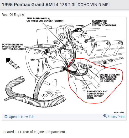
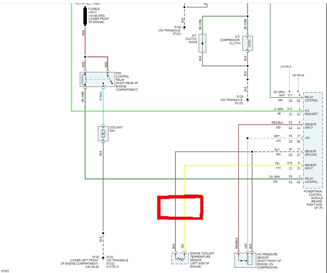
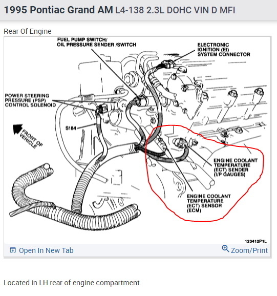
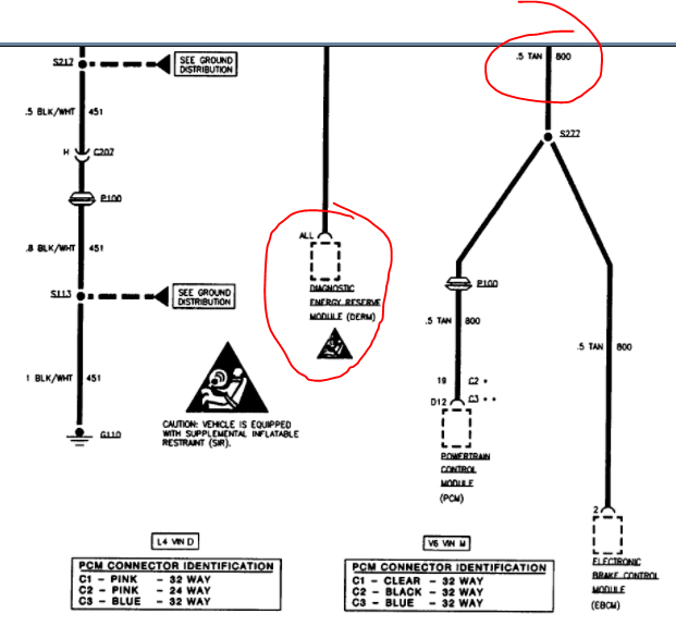
1. One unit supposed to be the sensor according to the schematic drawing attached here ( marked with a red surrounding shape) (and given a number 1 in the fourth attachment too), its connector is a rather large white one.
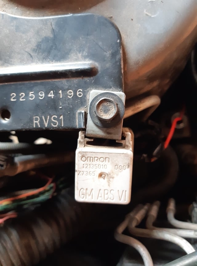
2. Right below that( or to the right side of it as in the fourth attachment); there is another one having a connector female part that is broken off ( but the 2 metal pins are still protruding out as you can clearly see), I gave it the number 2 in the fourth attachment. This sensor ( or may be sender) unit is anonymous to me since it is an obsolete part of the engine I have: which wires and colors should be attached to it and what does it serve?
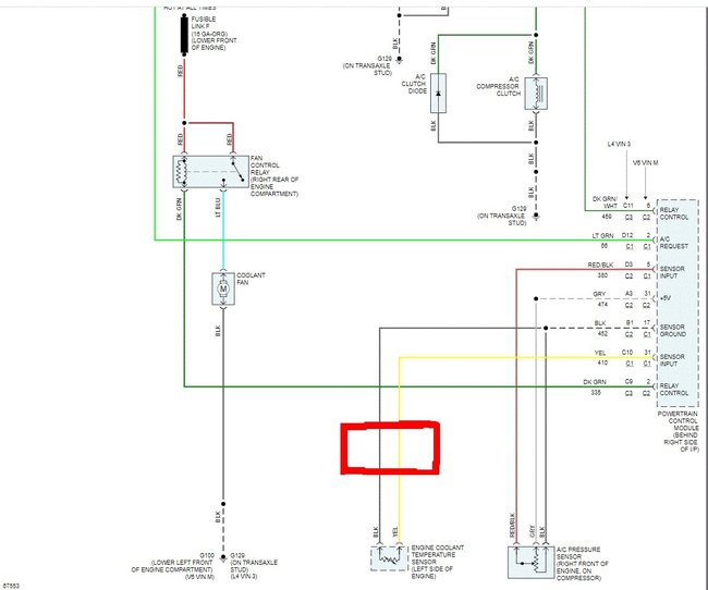
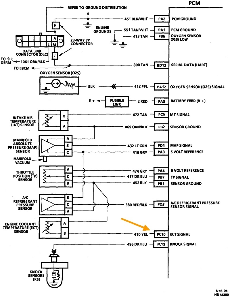
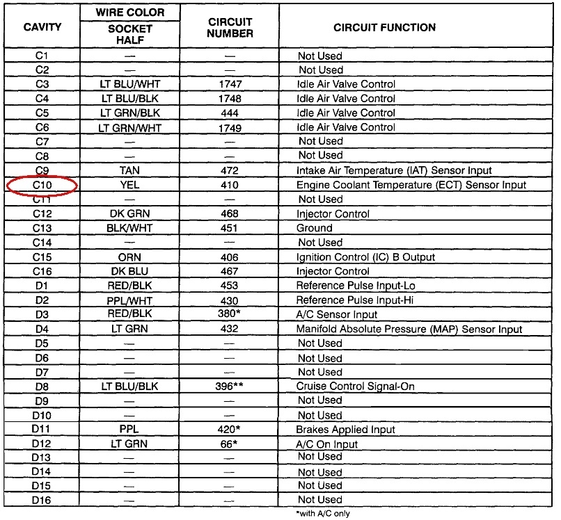
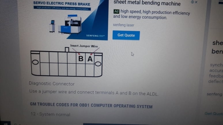
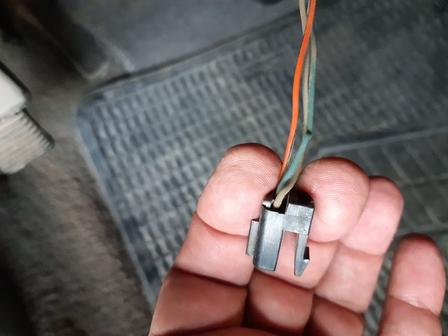
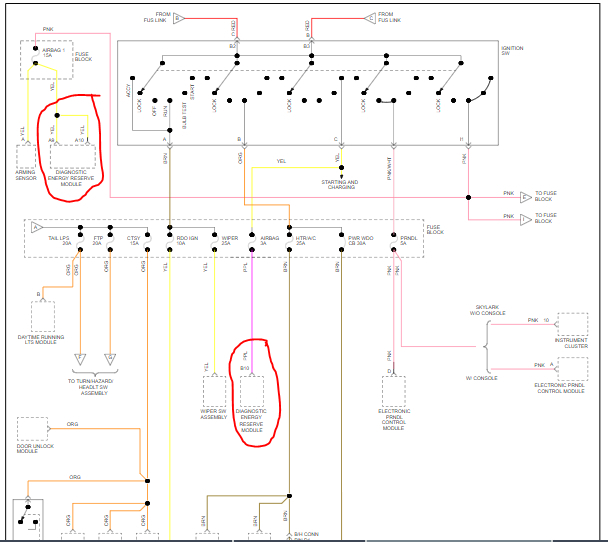
3. To the left side of both sensors mentioned above here( points 1 and 2) there is what I may call as ( the ECT sensor) that is supposed to relay the temperature to the ip/ temp gauge. Somehow; your generous reply mentioned a single wire only for this unit but I have 2 instead: a black and a yellow ones. Currently, its connector( a rather small black connector if compared with the white ones in points 1 and 2 above here which carries two wires right from the same harness: a black wire and a yellow wire. These two wires conform to the information given in the second attachment here: yellow and black wires leading to pins ( 31 c1 and 17 c1 of the PCM, respectively), they had been verified to be the right wires for this sensor since the gauge in the instruments panel works normally with them used like this.
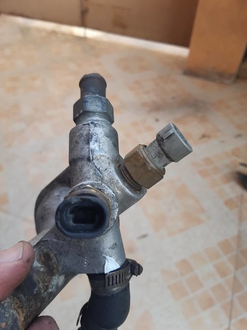
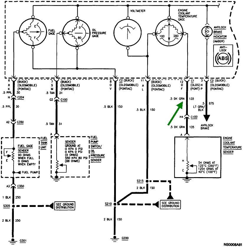
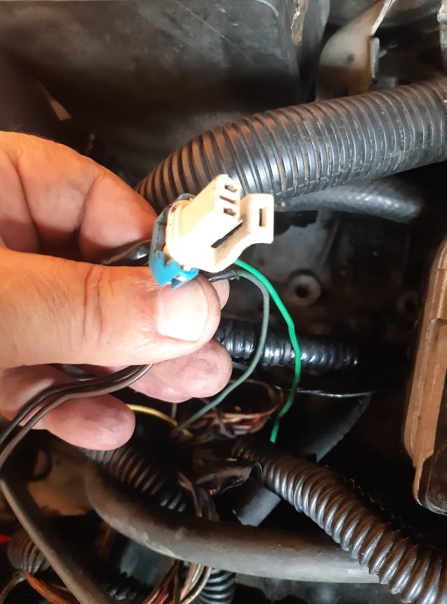
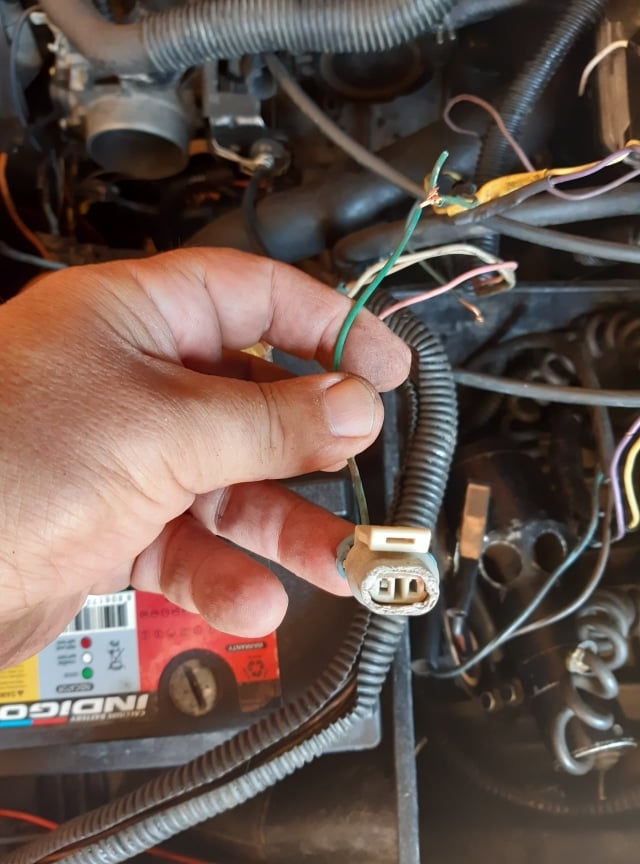
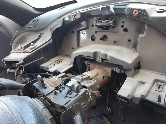
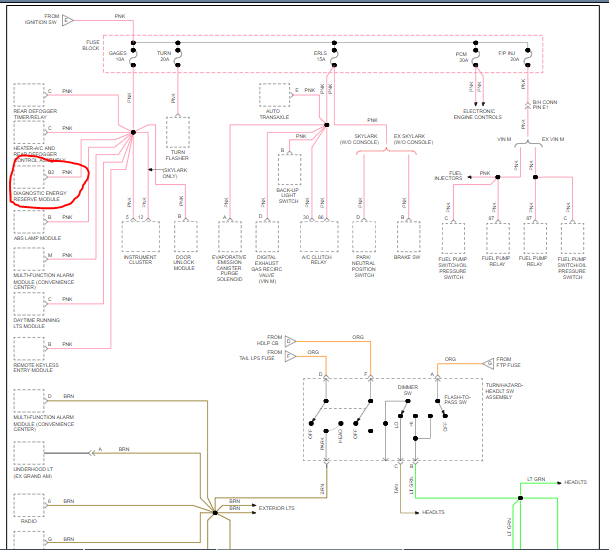
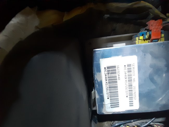
So the puzzling thing is the ect sender unit: the third attachment here shows the current available connector and wires: a green and a blue couple of wires: I need to know the followings please:

I. Should I use this connector as it is to make the sender unit work normally and be communicating with the PCM in the right manner? I mean with the two wires or is it the green wire only that should be there?
Ii. Which pins (in any one of the pcm c1 or c2 pink connectors) are relevant to these two wires( green and blue)?
Iii. How to test this circuit( of the sender) in may be the same way you have just kindly elaborated as per the sensor unit?
I appreciate your patience with my case, I am desperate to finish this problem that did cost me a lot so far and pushed me to the verge of total despair.
Was this
answer
helpful?
Yes
No
Wednesday, July 28th, 2021 AT 7:22 PM
Tiny
YASIRDAHHAM
  • MEMBER
  • 186 POSTS
Dear CARADIODOC: Going through the files you have just posted I find most of my queries answered, the connector of the ECT sensor turned out to be a single wire (and a dark green one specifically) connector, the 3rd image sent by me to you was misleading me, it is an extension and not a continuous genuine wire of the harness, someone used this connector with some 20 cm length of dark brown wires (two ones) taken from another engine harness (second hand), he connected the two brown wires to the dark green and the blue wires hanging from the harness, hence the confusion I had. The blue wire might be for the Knock sensor unit. Thanks once more to you dear sir.
Was this
answer
helpful?
Yes
No
Thursday, July 29th, 2021 AT 12:27 PM
Tiny
CARADIODOC
  • MECHANIC
  • 33,727 POSTS
I was going to say you had the two sensors mixed up, then I saw your second reply where you figured that out already. Two-wire coolant sensors are always for the Engine Computer and single-wire sensors are for the instrument cluster. In later years they just use the two-wire sensor for both functions.

If the dash gauge is working, we know the circuit for the single-wire sensor is okay. The best way to tell if the two-wire sensor is working is to read the engine temperature on a scanner. If you don't have one, measuring the voltage on the yellow wire will also tell you if that circuit is working properly. You don't want to find 0 or 5.0 volts there. The acceptable range is roughly 0.5 to 4.5 volts. Anything outside that range is what gets detected as a defect and sets a diagnostic fault code.

Have you read the fault codes? Look at this page:

https://www.2carpros.com/articles/buick-cadillac-chevy-gmc-oldsmobile-pontiac-gm-1983-1995-obd1-code-definitions-and-retrieval-method

to see how to read the codes without a scanner or code reader. If there is no fault code set for the coolant temperature sensor, there's no need to be looking in that circuit.

Also be aware the coolant temperature sensor and the throttle position sensor won't cause engine stalling. They will only cause very minor engine performance problems. The best suspect is the crankshaft position sensor circuit. You replaced the sensor already, but wiring and connector terminals should be checked too. The best way to identify an intermittent sensor is to watch the signal on a scanner. See if it goes away when the engine stalls. Most scanners have some means of indicating whether that signal is showing up while cranking the engine. If that signal is missing, you won't have spark or injector pulses.

Check for spark immediately after the engine stalling occurs.

https://www.2carpros.com/articles/how-to-test-an-ignition-system

If you do still have spark, we have to look at the fuel supply system.
Was this
answer
helpful?
Yes
No
+1
Thursday, July 29th, 2021 AT 7:59 PM
Tiny
YASIRDAHHAM
  • MEMBER
  • 186 POSTS
1. Okay dear friend, so far so good, I checked the voltage on the yellow wire of the ECT sender and it was around 3.5-4 volts, (sounds good), yet the engine still stalls all of a sudden which demands more investigations.
2. The part about OBD1 checking: I tried scanning my car 2 times but to no avail, each time it would say ( No Communication Established) or some phrase like that. The current link is very encouraging if not for a little obstacle: My DLC has only 3 wires, one in the upper row of the DLC connector ( extreme right side)while two of them are in the lower row ( extreme right side too) as you can see in the attached images( 1 and 2) when comparing it to the diagram given in the link provided by you( image 3), as if the line diagram is an upside down of mine. Should I overlook this position issue and jumper the two adjacent pins? Lots of thanks to you for your patience and help.
Was this
answer
helpful?
Yes
No
Friday, July 30th, 2021 AT 7:44 AM
Tiny
CARADIODOC
  • MECHANIC
  • 33,727 POSTS
Yes, connect the two adjacent terminals to read the codes. My experience has been those two wires will always be right next to each other in one corner of that connector, and there will never be another pair of adjacent wires in any of the other three corners. There will be either just one wire or no wires in those other corners.

I also remember there were some unusual 1995 GM models when it comes to reading the fault codes this way. This lead up to the OBD2 emissions systems that were required on all 1996 models sold in the U.S. A code reader or a scanner were needed to read the three-digit codes in those models.

Some of those late '95 models would not flash the codes by jumping the two wires. Even most aftermarket scanners wouldn't work. Codes and data had to be read with the dealer's scanner. That was called the "Tech 2". You can actually still find those new on eBay for a real lot less than the dealers had to pay for them.
Was this
answer
helpful?
Yes
No
+1
Friday, July 30th, 2021 AT 6:18 PM
Tiny
YASIRDAHHAM
  • MEMBER
  • 186 POSTS
Thanks to you dear sir, I will conduct the test today and be reverting back to you. Yesterday I took both ECT units (sensor and sender) off and drove without them, I also treated the 8 pins of the Ignition control module using a pointed tool to make them grip better. For the first time since last January I was driving for some 20 km without any interruption or stalling. I went for this act because one of the ignition control module caused hesitation in the engine RPM and eventual stalling when an electrician tried checking for continuity for the 8 wires. I will be back for more as I will be driving the car to a farther location today, a test that can give an idea about the current update.
PS: Attached here is the image of the original connector for the ECT sensor, a " one-eyed connector" with a green wire. This replaces the wrong one that was used, the one with 2 wires, I had been privileged by your presence on this thread.
Was this
answer
helpful?
Yes
No
Friday, July 30th, 2021 AT 11:47 PM
Tiny
YASIRDAHHAM
  • MEMBER
  • 186 POSTS
Hi dear CARADIODOC:
1. I conducted the test for the DLC but to my disappointment it came with no flashing of the (Service Engine Soon)!. There seems to be some discontinuity in what I may envision as the data link line. When I took of the whole dashboard mass weeks ago ( searching for some suspicious line or component) I found a male clip/connector with 3 wires( 1st attachment here) hanging loose from the right side of the steering wheel column, I couldn't find any female /connector in its vicinity to link this to that. I inquired on this website( in another thread) about it and some friend here suggested that it relates to a (security system) that is my car seems to have never been provided with. This is the image of it, its wires have 2 resembling 2 wires ( in color) of the DLC own wires (I may be mistaken here). The rest of attached images are for the dismantled dashboard. Kindly preview the answer of our friend Joe here on that thread regarding this lonesome connector and its wires:

" Did the vehicle come with a factory alarm? I believe that is a connection for it. The one wire appears orange, is that correct? The other two is one blue? It looks damaged in the pic, and the last one gray or tan?

As far as the DLC, those are the correct color wires. The black one with a white tracer should have continuity to ground. See pic 1 below.

Pic 2 below shows the data link connector, identifies each pin and shows locations. I highlighted the ones relevant to your vehicle. This is an OBD1 system. Here is a link that explains how to retrieve codes.

As far as an OBD1 system, they usually didn't supply power. Do me a favor. Follow the link below and let me know if you get codes. All you need to do this is a short jumper wire or even a paper clip. Here is the link. You will be jumping pins A and B. See directions.

https://www.2carpros.com/articles/buick-cadillac-chevy-gmc-oldsmobile-pontiac-gm-1983-1995-obd1-code-definitions-and-retrieval-method

Let me know if you get anything via that method. Also, please make sure the wires to your DLC are taped with electrical tape or shrink wrap. You don't want them shorting out and they look a bit rough. Also, if you get no signal via the check engine light, confirm you have continuity to ground via the black wire with the white tracer."
(Quoting ended ).

2. Latest update regarding the stalling issue: I drove for more than 30 km with no problem except the (Service Engine Soon) light always on, yet as I parked my car into my garage it went off all by itself. The service light was still on all the time even when the engine was working alright all day long.
Was this
answer
helpful?
Yes
No
Saturday, July 31st, 2021 AT 12:17 PM
Tiny
CARADIODOC
  • MECHANIC
  • 33,727 POSTS
I'm not familiar with that connector, but it looks like one that would slide onto the edge of a circuit board that's inside a housing. The clip on the lower right is typical of what latches it to the housing, and has to be pressed to release that plug.
Was this
answer
helpful?
Yes
No
+1
Saturday, July 31st, 2021 AT 6:27 PM
Tiny
YASIRDAHHAM
  • MEMBER
  • 186 POSTS
If it turned out to be relevant to data info then it might be the missing thing that is aborting any scanning so far, otherwise I may need to trace the DLC three wires to find some clue. In that other thread I was advised to check the black wire (with a white tracer) for continuity, I did and there was a reading, yet how come a whole OBD DLC connector be missing to have any line wire? Six months ago I tried to guess why my engine was rough, the guy who had an old bulky scanner conducted a scanning and it gave a result of having the Oxygen sensor not working, just what could have happened later to that causing the DLC to go that dead?
Was this
answer
helpful?
Yes
No
Sunday, August 1st, 2021 AT 1:35 AM
Tiny
DANNY L
  • MECHANIC
  • 5,648 POSTS
Hello, I'm Danny.

I've attached a few pictures from a wiring diagram relating to the diagnostic energy reserve module. Have you tracked-tested this module? Are you still not getting any signal or communication with the DLC- Data Link Connector? Hope this helps and thanks for using 2CarPros.
Was this
answer
helpful?
Yes
No
+1
Sunday, August 1st, 2021 AT 2:35 AM
Tiny
YASIRDAHHAM
  • MEMBER
  • 186 POSTS
Hello dear Danny. Sad to say that the problem is still there, it used to disappear for a few days with at least two changes from our long thread with you and Joe before reoccurring once again, it puzzles me how can a malfunction be off for hours and then be back again as if a demon. I went through the 4 attachments here, the first two are
visible unlike the 3rd and 4th images. Nevertheless, the thing called (Diagnostic Energy Reserve Module) doesn't seem to be there in my car unless the connector and 3 wires ( whose image is attached here) is the one that used to be clipped into that module. What exactly does such a module do? I am intrigued.
Was this
answer
helpful?
Yes
No
Sunday, August 1st, 2021 AT 8:52 AM
Tiny
YASIRDAHHAM
  • MEMBER
  • 186 POSTS
Dear CARADIODOC, I would like to bring your kind attention to what my friend Danny L mentioned about a " diagnostic energy reserve module". I Googled the term and it looks like an Airbag-relevant module, do you agree?
Was this
answer
helpful?
Yes
No
Sunday, August 1st, 2021 AT 12:41 PM
Tiny
YASIRDAHHAM
  • MEMBER
  • 186 POSTS
There is another phenomena with my engine: Every time the engine is repeating its stalling ( while in my garage)I be hearing a hissing sound coming from the fuel line as I a positively think. I shot a brief video for it just for the audio part of it which I think is audible in the attached video. Sometimes I tend to consider this issue of stalling as about a fuel delivery discontinuity rather than an electrical issue. This misgiving is because it happened quite too many times that I am driving my car and the RPM pointer drops dead all of a sudden but a sustained pressing down of the fuel accelerator pedal gets the pointer to rise again and the engine simply resumes its functioning. I believe that with an automatic transmission like mine it is not normal to see this thing happening as in an orthodox gearbox car where we press down the clutch pedal when the engine dies while driving, then we shift the manual gear to some high gear and upon releasing the pressure off the clutch pedal the engine gets back to running status.
Was this
answer
helpful?
Yes
No
Sunday, August 1st, 2021 AT 12:51 PM
Tiny
CARADIODOC
  • MECHANIC
  • 33,727 POSTS
The hissing sound is the gas rushing through the fuel pressure regulator. That will stop the instant the fuel pump turns off, which is a few seconds after the engine stops running.
Was this
answer
helpful?
Yes
No
+1
Sunday, August 1st, 2021 AT 8:17 PM
Tiny
YASIRDAHHAM
  • MEMBER
  • 186 POSTS
This one took several minutes! Not less than 3 or 4 when I shot this clip yesterday. I will try to record the time duration of it today.
Was this
answer
helpful?
Yes
No
Monday, August 2nd, 2021 AT 12:43 AM
Tiny
CARADIODOC
  • MECHANIC
  • 33,727 POSTS
The fuel pump shouldn't run more than a few seconds after the engine stops rotating. If you're hearing a hissing noise long after that, it has to be from something else. Possibly expanding coolant going into the reservoir?
Was this
answer
helpful?
Yes
No
+1
Monday, August 2nd, 2021 AT 8:03 PM
Tiny
YASIRDAHHAM
  • MEMBER
  • 186 POSTS
I turned the engine yesterday to repeat the case but it didn't occur. Next time I will be using a stethoscope to trace the sound. Your suggestion looks reasonable since there is that thin metal pipe right over the exhaust manifold carrying hot coolant back to the coolant reservoir. Thanks to you dear friend.
Was this
answer
helpful?
Yes
No
Monday, August 2nd, 2021 AT 9:38 PM
Tiny
ASEMASTER6371
  • MECHANIC
  • 52,797 POSTS
Please post the video if you can so we can hear it and help track down the source of the issue for you.

If you are happy with our responses, please feel free to write a review for us on google.

https://www.sitejabber.com/reviews/2carpros.com

Roy
Was this
answer
helpful?
Yes
No
+1
Friday, August 6th, 2021 AT 1:25 PM
Tiny
YASIRDAHHAM
  • MEMBER
  • 186 POSTS
Luckily I did today, it lasted more than 10 minutes, using my son's stethoscope didn't help me pinpoint its source but by mere chance I took this relay (shown in the first and second attachment, supposed to be the Airbag relay as my mechanic says) of its metal base via unscrewing the bolt( that was while tracing the orange/black wire of the DLC), it led to terminating that hissing (and ticking) sound at once. The third attachment is for the sound that lasted too long to relate to the Fuel Pump or fuel return line. I will visit your site right now.
Was this
answer
helpful?
Yes
No
Friday, August 6th, 2021 AT 1:55 PM

Please login or register to post a reply.

Sponsored links