That's called "memory steer", and you're describing a really serious case of it. On older heavy vehicles that used king pins, those could become tight and bind to the point of causing loud creaking noises when turning. It's much less common for a ball joint to become tight like that, but this is fairly common on vehicles with front struts, like yours. The struts have an upper strut mount with bearings inside it. The coil spring and that mount support all of the weight in that corner of the van, and they have to be free to rotate as you turn the steering wheel. Dirt and rust can get in there, or the rolling surfaces just break apart and prevent the ball bearings from rolling freely.
These upper mounts can be replaced separately, but it is somewhat of a dangerous procedure, even for specialists. It involves compressing the coil spring so it can be removed, the same as we would do when replacing just the struts. This can put the spring under more than 1000 pounds of pressure. I've seen two come flying out of the compressor while at the dealership. One took out an eight-foot overhead light fixture. Mine went sailing out of the shop, through the open garage door, and through the parking lot. I don't recommend an inexperienced do-it-yourselfer attempt this job.
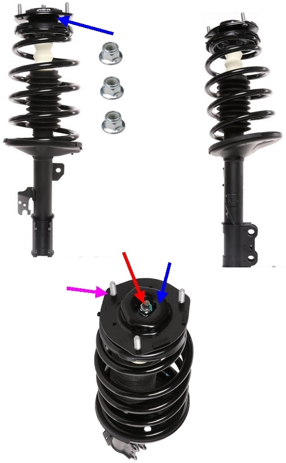
There's a better alternative that is a really good value. Based on the age of your van, the coil springs are going to be sagged and ride height will be lower than the published legal specification. We get really picky about that when aligning vehicles. The second issue is mileage affects the life of the struts. The mileage you listed suggests it's time to replace the struts. The age suggests it's probably time to replace the springs. The binding steering sounds like the upper mounts are binding. All three of those parts are available already assembled and ready to install as what's commonly called a "Quick Strut". If you have this done at a shop, you'll pay only a little more for the parts, but you'll save about half the labor cost. Either way an alignment is needed after this service.
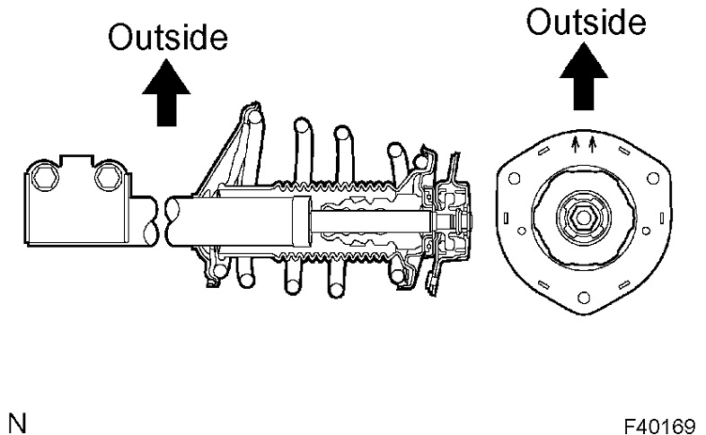
This photo shows what a Quick Strut for your van looks like. The blue arrows are pointing to the upper mount where the bearing assembly is inside. The purple arrow is pointing to one of the three mounting bolts you might be able to see under the hood, very near the hood hinges. The coil spring is held captive under pressure by the nut with the red arrow. Never loosen or remove that nut unless the coil spring is compressed with a special tool. If that nut is unscrewed, when it lets go, the spring can easily kill someone when it comes flying out.
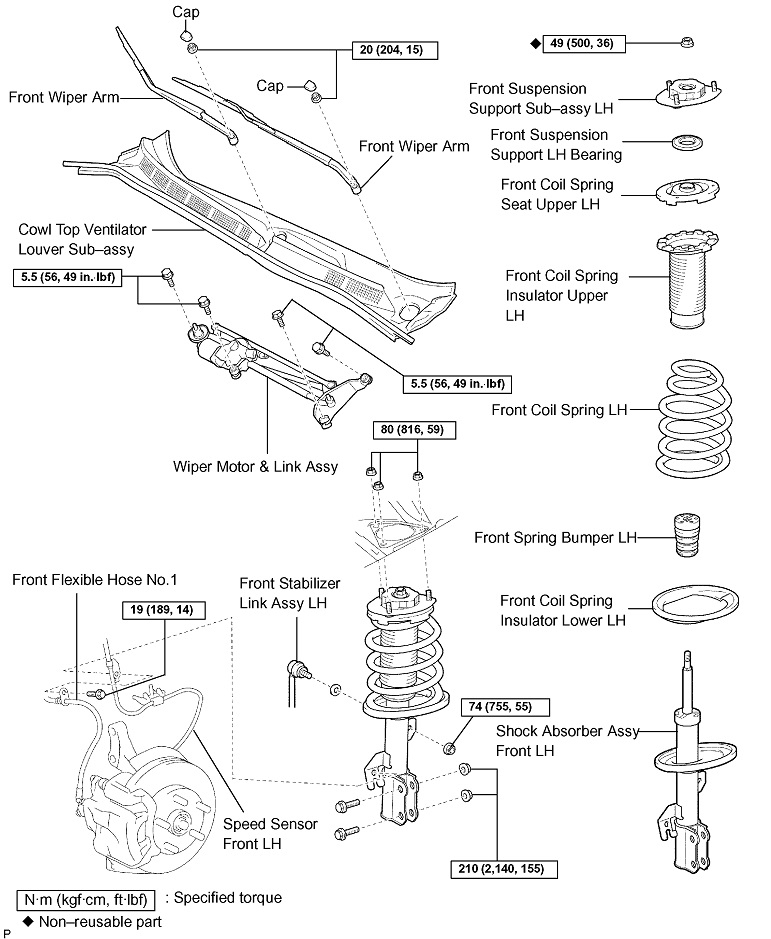
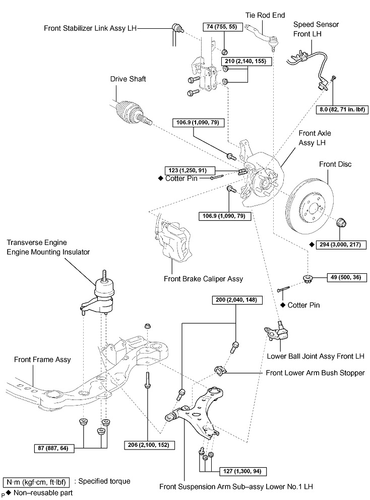
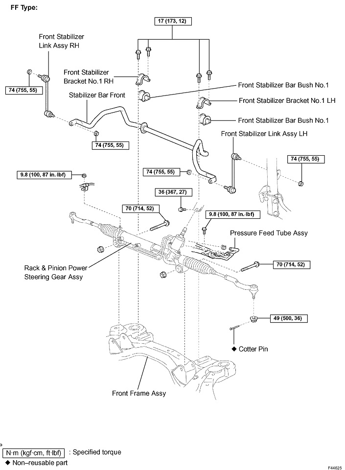
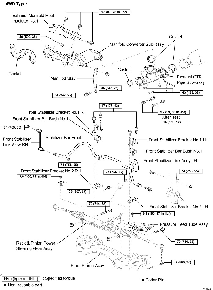
The rest of these drawings are Toyota's instructions for the strut replacement procedure when that is all that's being replaced. If you choose to replace the entire assemblies as I described, you only have to be concerned with the parts of these instructions related to that. The job will be a lot simpler than what is described here:
Drawing 1
Drawing 2
Drawing 3
Drawing 4
FRONT SHOCK ABSORBER WITH COIL SPRING
OVERHAUL
1. REMOVE FRONT WHEEL
2. REMOVE FRONT WIPER ARM HEAD CAP
3. REMOVE FR WIPER ARM RH
4. REMOVE FR WIPER ARM LH
5. REMOVE COWL TOP VENTILATOR LOUVER SUB-ASSY
6. REMOVE WINDSHIELD WIPER MOTOR & LINK ASSY
Drawing 5
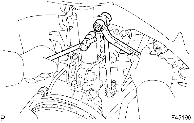
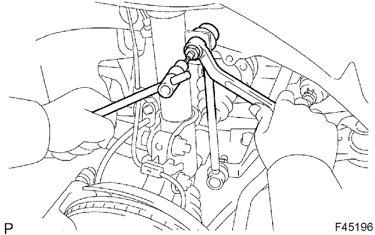
7. DISCONNECT FRONT STABILIZER LINK ASSY LH
a. Remove the nut and disconnect the front stabilizer link assy LH from the shock absorber assy front LH.
HINT: If the ball joint turns together with the nut, use a hexagon (6 mm) wrench to hold the stud.
Drawing 6
8. REMOVE FRONT SHOCK ABSORBER WITH COIL SPRING
a. Loosen the lock nut.
NOTICE:
Do not loosen the nut except for the purpose of disassembling the shock absorber assy front LH with coil spring.
Do not remove the lock nut.
Drawing 7
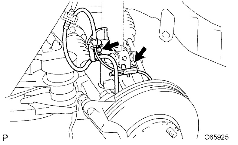
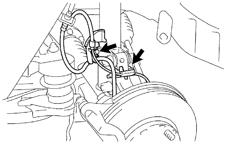
b. Remove the bolt, disconnect the front flexible hose No.1 and speed sensor front LH.
Drawing 8
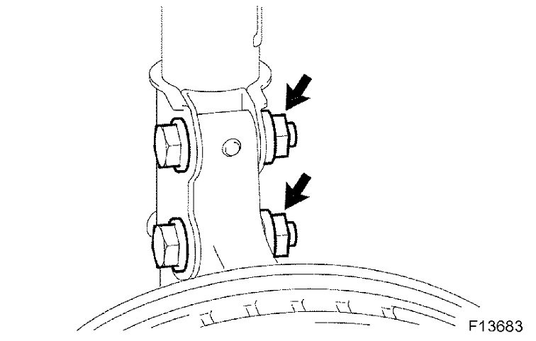
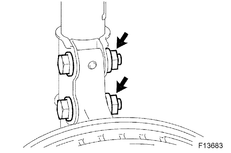
c. Remove the 2 nuts and 2 bolts on the lower side of front shock absorber with coil spring.
NOTICE: When removing the bolt, hold the nut not to rotate.
Drawing 9
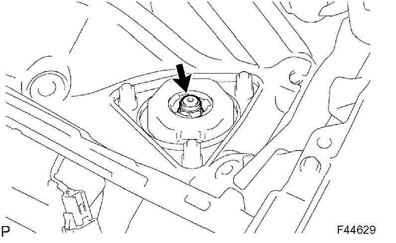
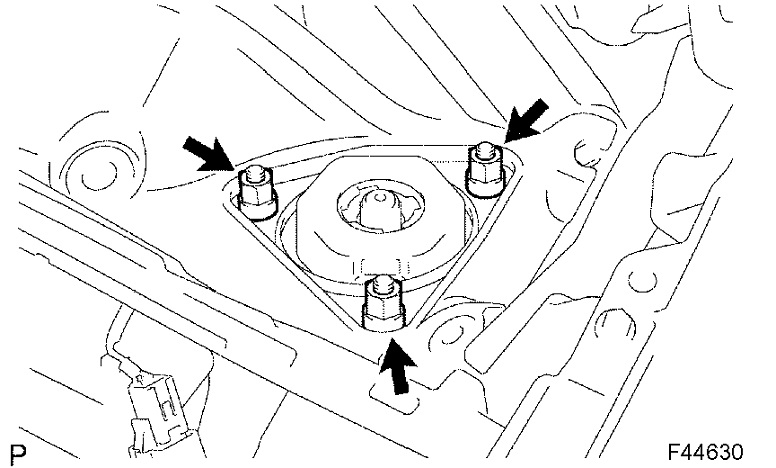
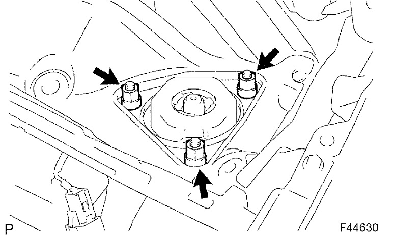
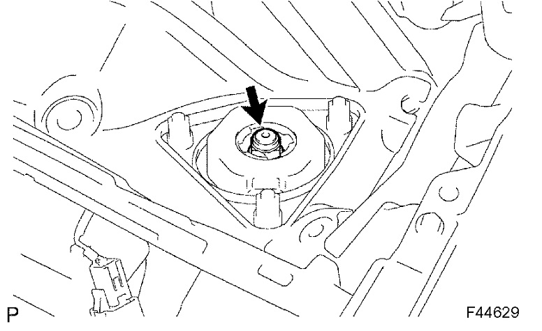
d. Remove the 3 nuts on the upper side of the front shock absorber with coil spring.
E. Remove the front shock absorber with the coil spring.
Drawing 10
9. FIX FRONT SHOCK ABSORBER WITH COIL SPRING
a. Install 2 nuts and a bolt to the bracket at the lower side of the front shock absorber with coil spring and secure it in a vise.
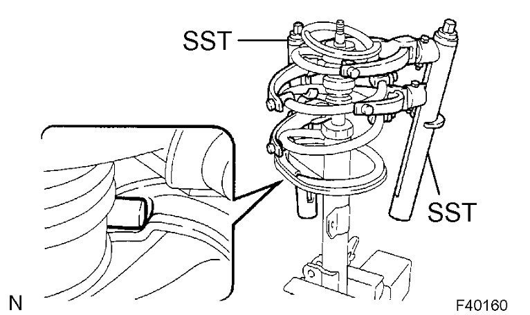
10. REMOVE FRONT SUSPENSION SUPPORT SUB-ASSY LH
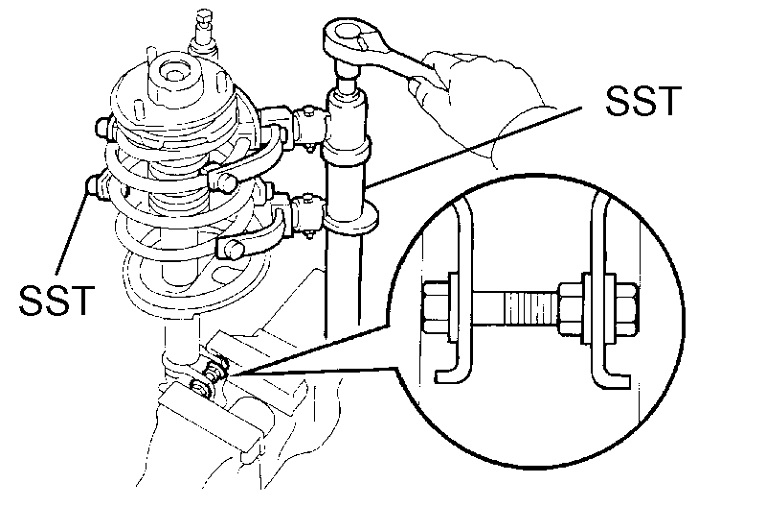
a. Using SST, compress the front coil spring LH.
SST 09727-30021 (09727-00010, 09727-00021, 09727-00031)
NOTICE: Do not use an impact wrench. It will damage the SST.
HINT: Use 2 SST of the same type.
B. Remove the lock nut and the front suspension support sub-assy.
11. REMOVE FRONT SUSPENSION SUPPORT LH BEARING
12. REMOVE FRONT COIL SPRING SEAT UPPER LH
Drawing 11
13. REMOVE FRONT COIL SPRING INSULATOR UPPER LH
14. REMOVE FRONT COIL SPRING LH
15. REMOVE FRONT SPRING BUMPER LH
16. REMOVE FRONT COIL SPRING INSULATOR LOWER LH
17. REMOVE SHOCK ABSORBER ASSY FRONT LH
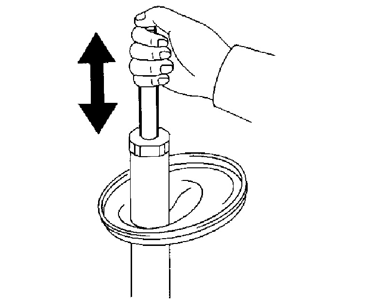
18. INSPECT SHOCK ABSORBER ASSY FRONT LH
a. Compress and extend the shock absorber rod and check that there is no unusual resistance or unusual sound during operation.
If there is any abnormality, replace the shock absorber assy front LH with a new one.
NOTICE: When disposing of the shock absorber assy front LH, see DISPOSAL.
19. INSTALL SHOCK ABSORBER ASSY FRONT LH
20. INSTALL FRONT COIL SPRING INSULATOR LOWER LH
a. Install the front coil spring insulator lower LH onto the shock absorber assy front LH.
21. INSTALL FRONT SPRING BUMPER LH
a. Install the front spring bumper LH to the Piston rod.
Drawing 12
22. INSTALL FRONT COIL SPRING LH
a. Using SST, compress the front coil spring LH.
SST 09727-30021 (09727-00010, 09727-00021, 09727-00031)
NOTICE: Do not use an impact wrench. It will damage the SST.
HINT: Use 2 SST of the same type.
B. Install the front coil spring LH to the shock absorber assy front LH.
HINT: Fit the front coil spring insulator lower LH into the gap of the shock absorber assy front LH.
Drawing 13
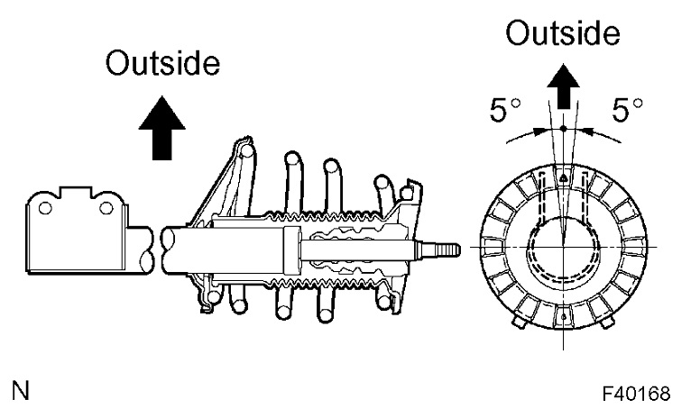
23. INSTALL FRONT COIL SPRING INSULATOR UPPER LH
a. Install the front coil spring insulator upper LH as shown in the illustration.
Drawing 14
24. INSTALL FRONT COIL SPRING SEAT UPPER LH
a. Install the front coil spring seat upper LH to the shock absorber assy front LH with the mark facing to the outside of the vehicle.
Drawing 15
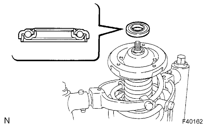
25. INSTALL FRONT SUSPENSION SUPPORT LH BEARING
a. Install the front suspension support LH bearing.
Drawing 16
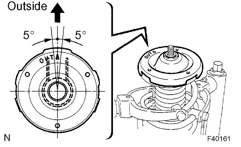
26. INSTALL FRONT SUSPENSION SUPPORT SUB-ASSY LH
a. Install the front suspension support sub-assy LH with the mark facing to the outside of the vehicle.
B. Temporarily tighten a new lock nut.
27. INSTALL FRONT SHOCK ABSORBER WITH COIL SPRING
a. Install the front shock absorber with coil spring as shown in the illustration.
Drawing 17
b. Install the 3 nuts to the upper side of front shock absorber with coil spring.
Torque: 80 Nm (816 kgf-cm, 59 ft. Lbs.)
Drawing 18
c. Install the 2 bolts and 2 nuts to the lower side of front shock absorber with coil spring.
Torque: 210 Nm (2,140 kgf-cm, 155 ft. Lbs.)
NOTICE: When installing the bolt, hold the nut not to rotate.
Drawing 19
d. Fully tighten the lock nut.
Torque: 49 Nm (500 kgf-cm, 36 ft. Lbs.)
Drawing 20
e. Install the front flexible hose No.1 and speed sensor front LH with the bolt.
Torque: 19 Nm (189 kgf-cm, 14 ft. Lbs.)
Drawing 21
28. INSTALL FRONT STABILIZER LINK ASSY LH
a. Install the front stabilizer link assy LH with the nut.
Torque: 74 Nm (755 kgf-cm, 55 ft. Lbs.)
HINT: If the ball joint turns together with the nut, use a hexagon (6 mm) wrench to hold the stud.
29. INSTALL WINDSHIELD WIPER MOTOR & LINK ASSY
30. INSTALL FR WIPER ARM LH
31. INSTALL FR WIPER ARM RH
32. INSTALL FRONT WHEEL
Torque: 103 Nm (1,050 kgf-cm, 76 ft. Lbs.)
33. INSPECT AND ADJUST FRONT WHEEL ALIGNMENT
Images (Click to make bigger)
Tuesday, April 13th, 2021 AT 8:38 PM