Hi,
I am going to provide the directions for replacement. Read through everything and in the install portion, it explains how to adjust height. The attached pics correlate with the directions.
___________________________________-
2002 Chevy Truck K 1500 Truck 4WD V8-5.3L VIN T
Torsion Bar Replacement
Vehicle Steering and Suspension Suspension Torsion Bar Service and Repair Procedures Front Suspension Torsion Bar Replacement
TORSION BAR REPLACEMENT
Torsion Bar Replacement
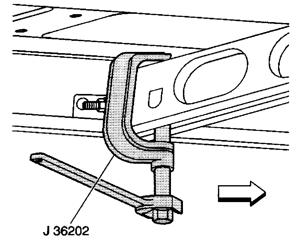
^ Tools Required
- J 36202 Torsion Bar Unloading/Loading Tool
Removal Procedure
Notice: Use care when handling the torsion bars in order to avoid chipping or scratching the coating. Damage to the coating will result in premature failure of the torsion bars.
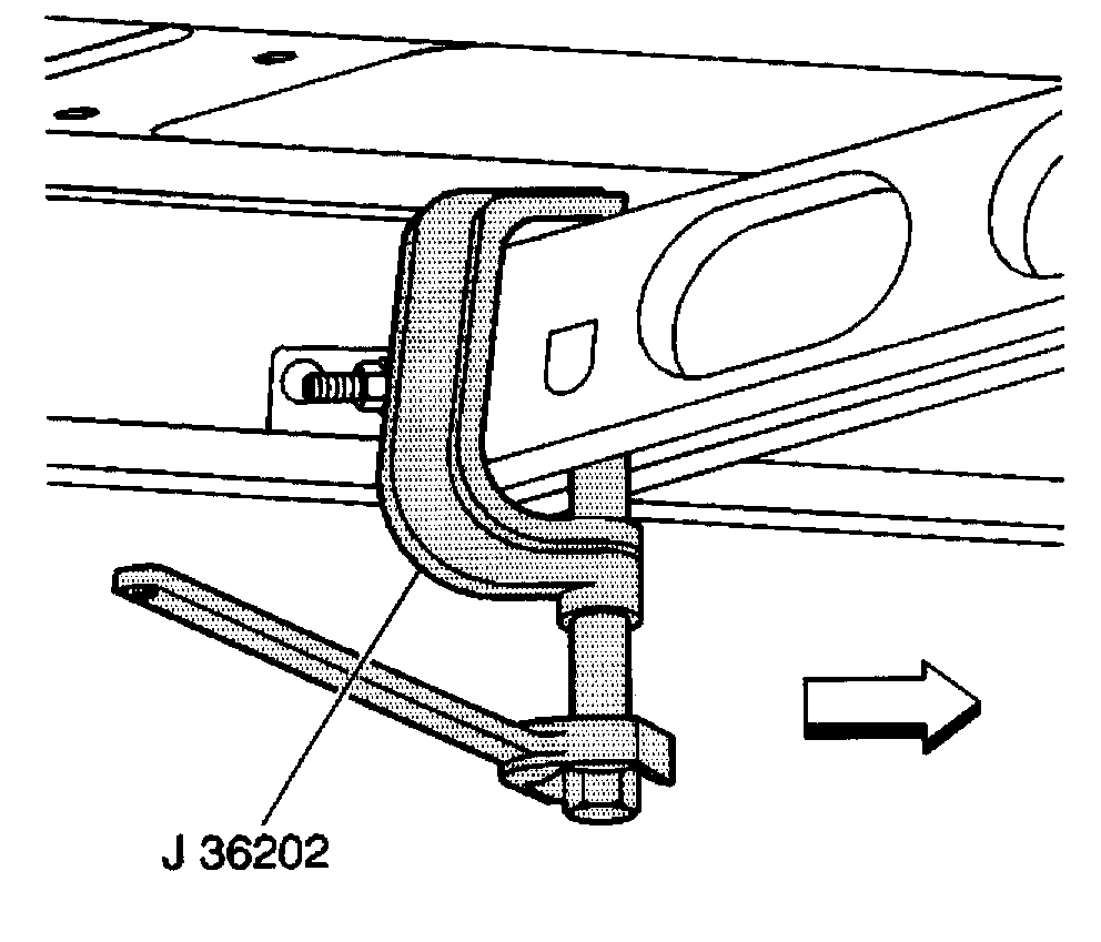
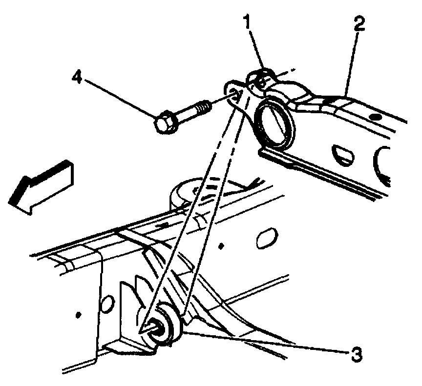
pic 1
1. Raise and support the vehicle. Refer to Vehicle Lifting.
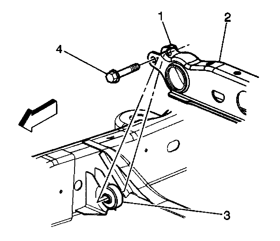
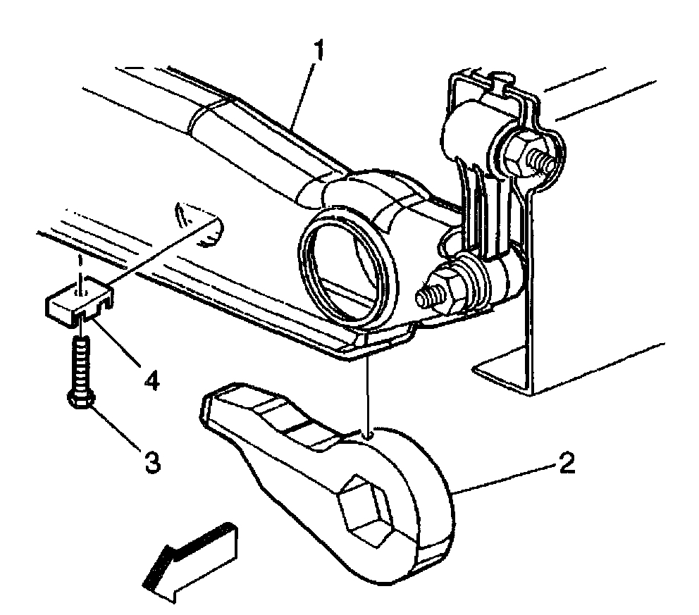
2. Install the J 36202 to the adjustment arm and the crossmember.
3. Increase the tension on the adjustment arm until the load is removed from the adjustment bolt and the adjuster nut.
Important: Mark the adjustment bolt and count the number of times that is required to remove the adjustment bolt.
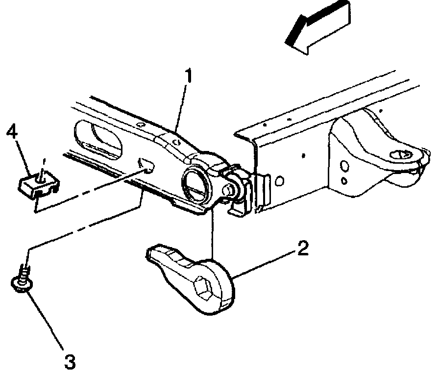
pic 2
4. Remove the adjustment bolt (3) and the adjuster nut (4).
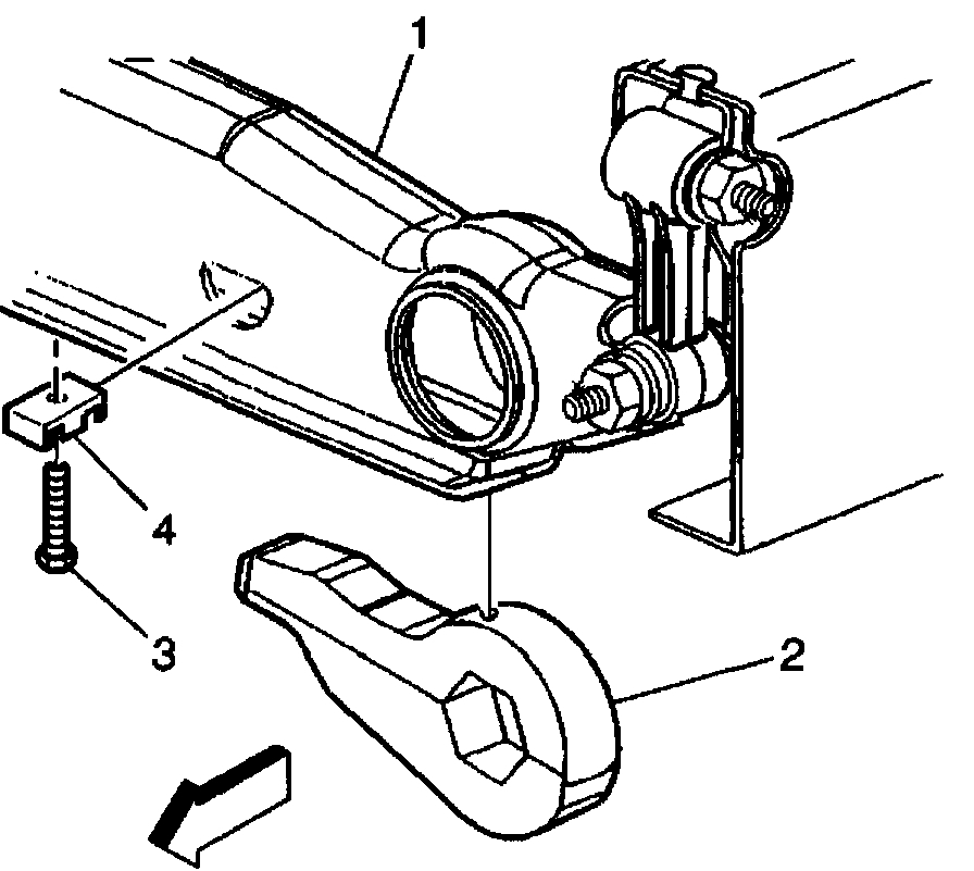
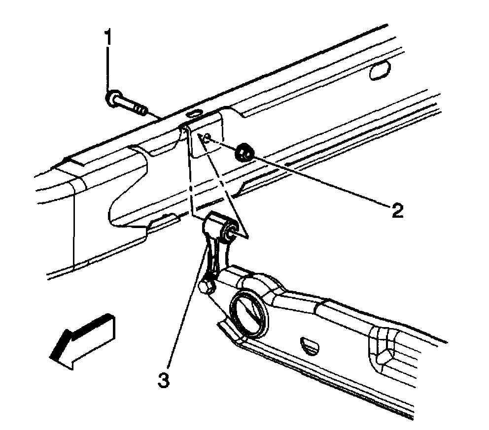
pic 3
5. Remove the adjustment bolt (3) and the adjuster nut (4), for vehicles with MN8, MT1 AND MW3.
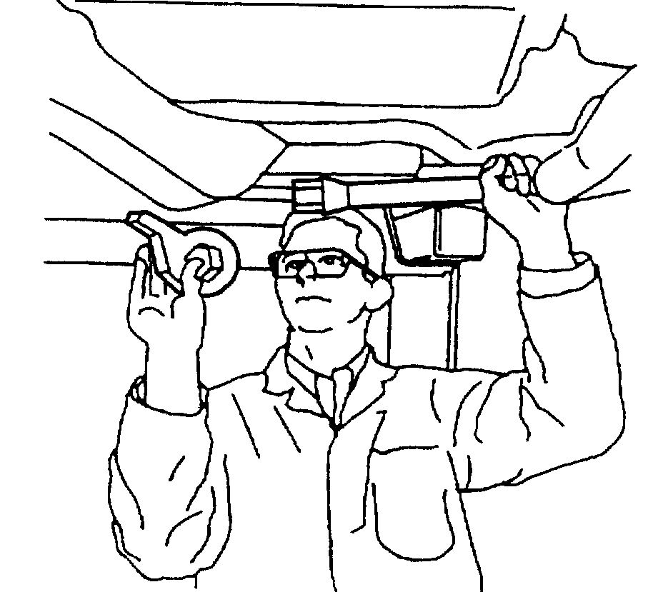
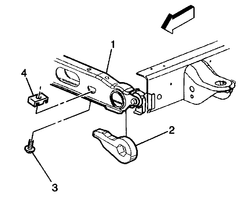
pic 4
6. Remove the J 36202, allowing the torsion bar to unload.
7. Remove the adjustment arm by sliding the torsion bar forward until the torsion bar clears the adjustment arm. Use your hand to support the adjustment arm as the adjustment arm releases from the torsion bar.
pic 5
8. Remove the torsion bar crossmember bolts (4) from the weld nuts (1).
pic 6
9. Remove the upper link mounting nuts (1) and the bolts (2).
10. Remove the torsion bar crossmember.
Important: Note the position of the torsion bars as the left and right bars are different.
pic 7
11. Remove the torsion bars from the vehicle.
Installation Procedure
pic 8
1. Install the torsion bars to the lower control arm.
pic 9
2. Install the torsion bar crossmember.
Notice: Refer to Fastener Notice in Service Precautions.
3. Install the torsion bar crossmember bolts (1) to the weld nuts (4).
^ Tighten the bolt to 95 Nm (70 ft. lbs.).
pic 10
4. Install the upper link mounting nuts and the bolts (3).
^ Tighten the nut to 95 Nm (70 ft. lbs.).
pic 11
5. While supporting the adjustment arm, slide the torsion bar rearward until the torsion bar fully engages the adjustment arm.
6. Install the J 36202 to the adjustment arm and the crossmember.
7. Increase the tension on the adjustment arm in order to load the torsion bar.
Important: Install the adjustment bolt the same amount of turns that were required to remove the bolt during removal.
pic 12
8. Install the adjustment bolt (3) and the adjuster nut (4).
pic 13
9. Install the adjustment bolt (3) and the adjuster nut (4), for vehicles with MN8, MT1 AND MW3.
10. Remove the J 36202 releasing the tension on the torsion bar until the load is taken up by the adjustment bolt.
11. Remove the safety stands.
12. Lower the vehicle.
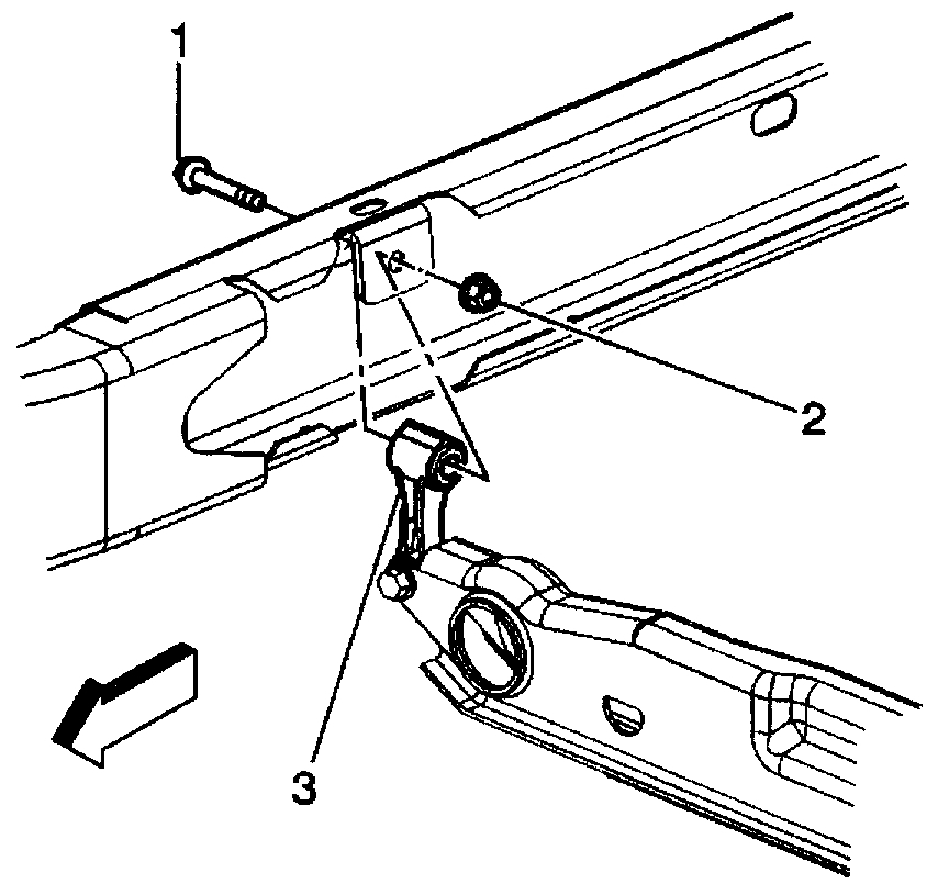
13. Measure the Z height.
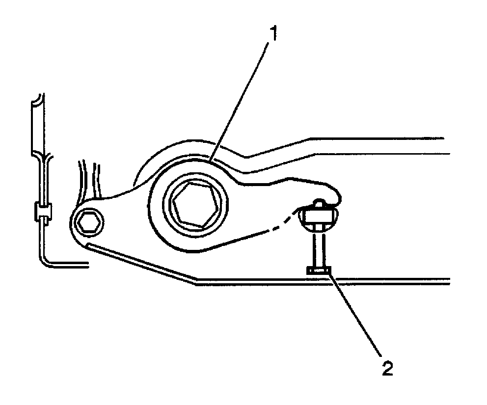
pic 14
14. Turn the adjustment bolt (2) clockwise to increase the Z height and counterclockwise to decrease the Z height.
_______________
Let me know if this helps.
Take care,
Joe
Images (Click to enlarge)
Mar 11, 2020 at 8:07 PM