Hi and thanks for using 2CarPros.
Okay, are you saying that timing was correct prior to rotating the crankshaft? If so, you should be fine. As long as it was aligned when you put it together. However, if something is loose or allowing it to get off a link, that is a problem. I am going to attache the shop directions for timing chain removal, replacement, and alignment. Read through them and confirm that you followed the directions and didn't miss anything. I am going to start with removal. All attached pictures will correlate with these directions.
_______________________
REMOVAL
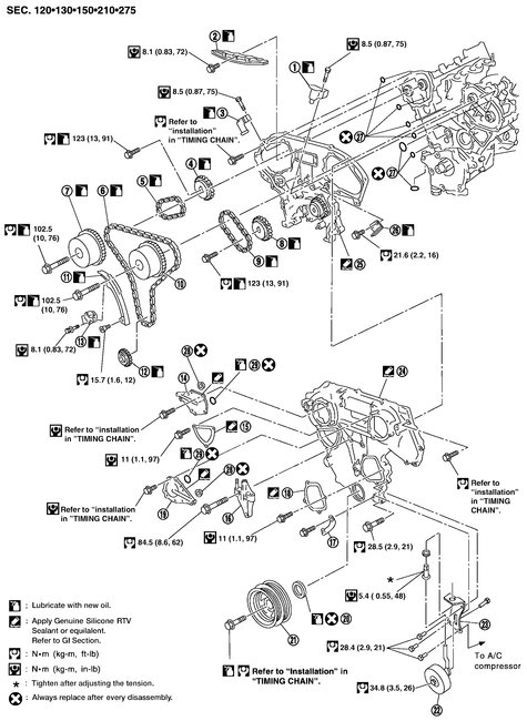
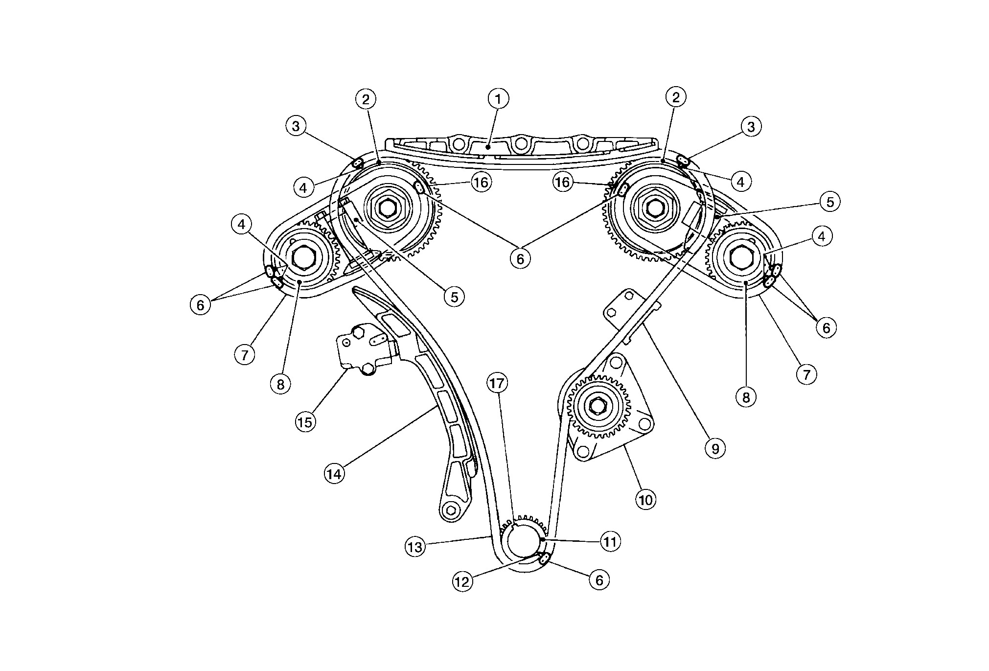
Picture 1
1. Timing chain tensioner
2. Internal chain guide
3. Timing chain tensioner
4. Camshaft sprocket (EXH)
5. Timing chain (secondary)
6. Timing chain (primary)
7. Camshaft sprocket (INT)
8. Camshaft sprocket (EXH)
9. Timing chain (secondary)
10. Camshaft sprocket (INT)
11. Slack guide
12. Crankshaft sprocket
13. Timing chain tensioner
14. IVT control valve cover - right
15. Chain tensioner cover
16. RH engine mounting bracket
17. Water hose clamp
18. Water pump cover
19. IVT control valve cover - left
20. Front oil seal
21. Crankshaft pulley
22. Idler pulley
23. Idler pulley bracket
24. Front timing chain case
25. Rear timing chain case
26. Timing tension guide
27. O-ring
28. Collared O-ring
29. Seal ring
CAUTION:
After removing timing chain, do not turn the crankshaft and camshaft separately, or the valves will strike the pistons.
When installing camshafts, chain tensioners, oil seals, or other sliding parts, lubricate contacting surfaces with new engine oil.
Apply new engine oil to bolt threads and seat surfaces when installing camshaft sprockets, camshaft brackets, and crankshaft pulley.
Before disconnecting fuel hose, release fuel pressure.
Before removing the upper oil pan, remove the crankshaft position sensor (POS).
Be careful not to damage sensor edges.
Do not spill engine oil or coolant on drive belts.
NOTE:
This section describes procedures for removal/installation procedure of the front timing chain case and timing chain related parts, and rear timing chain case, when oil pan (upper) needs to be removed/installed for engine overhaul, etc. If removing rear timing chain case, remove the engine assembly.
To remove/install front timing chain case, timing chain, and its related parts without removing oil pan (upper).
REMOVAL
Picture 2
1. Release the fuel pressure.
2. Disconnect the battery negative terminal.
3. Drain the engine cooling system.
4. Drain engine oil.
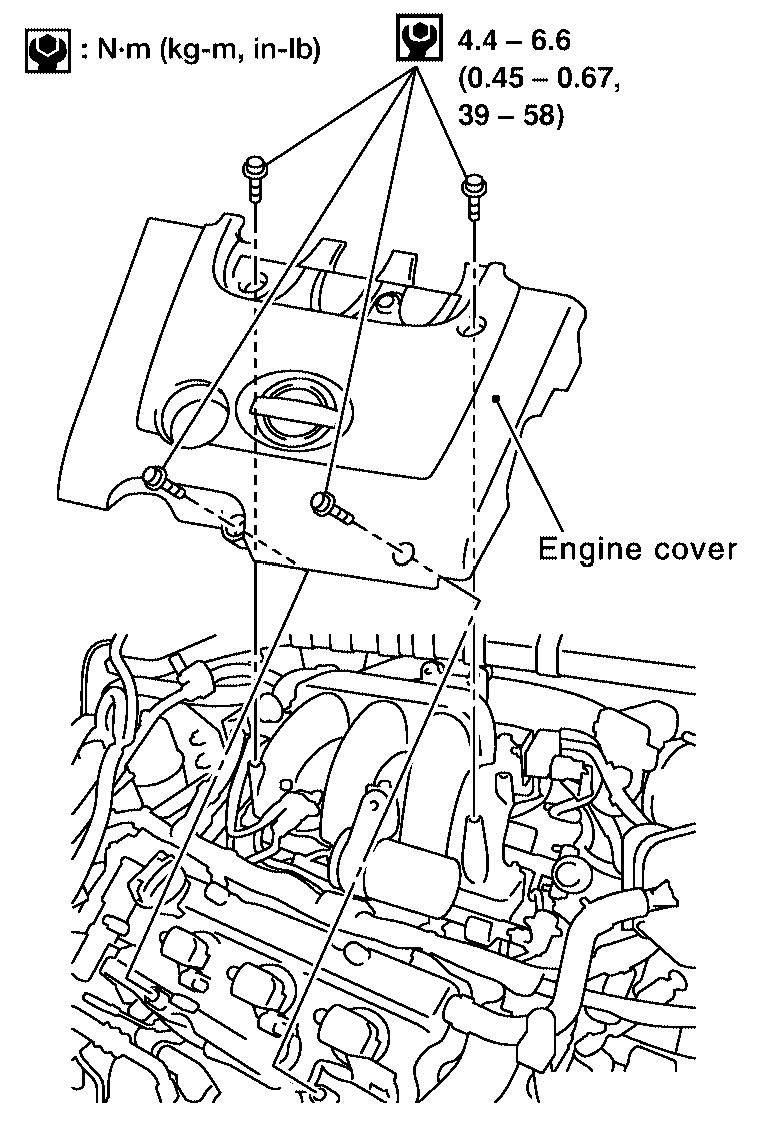
5. Remove engine cover using power tool.
6. Remove hood ledge covers.
7. Remove the intake air duct with the air cleaner case lid and mass air flow sensor.
8. Remove the engine coolant reservoir.
9. Disconnect the fuel rail quick connector at the vehicle piping side.
10. Remove the IPDM E/R and position aside. Remove the bracket.
11. Remove the windshield wiper assembly.
12. Remove the front RH wheel and tire using power tool.
13. Remove the engine undercover.
14. Remove the RH inner fender splash shield.
15. Remove the drive belts and idler pulley.
16. Recover the A/C system R134a and remove the A/C compressor.
17. Remove engine oil cooler pipe bolts.
18. Remove the power steering oil pump and reservoir tank with lines attached and position them aside.
19. Remove the generator.
20. Disconnect the engine harness and position aside.
21. Remove the A/C low pressure line.
22. If necessary, support the engine and remove the RH engine mounting insulator, mount and bracket.
Picture 3
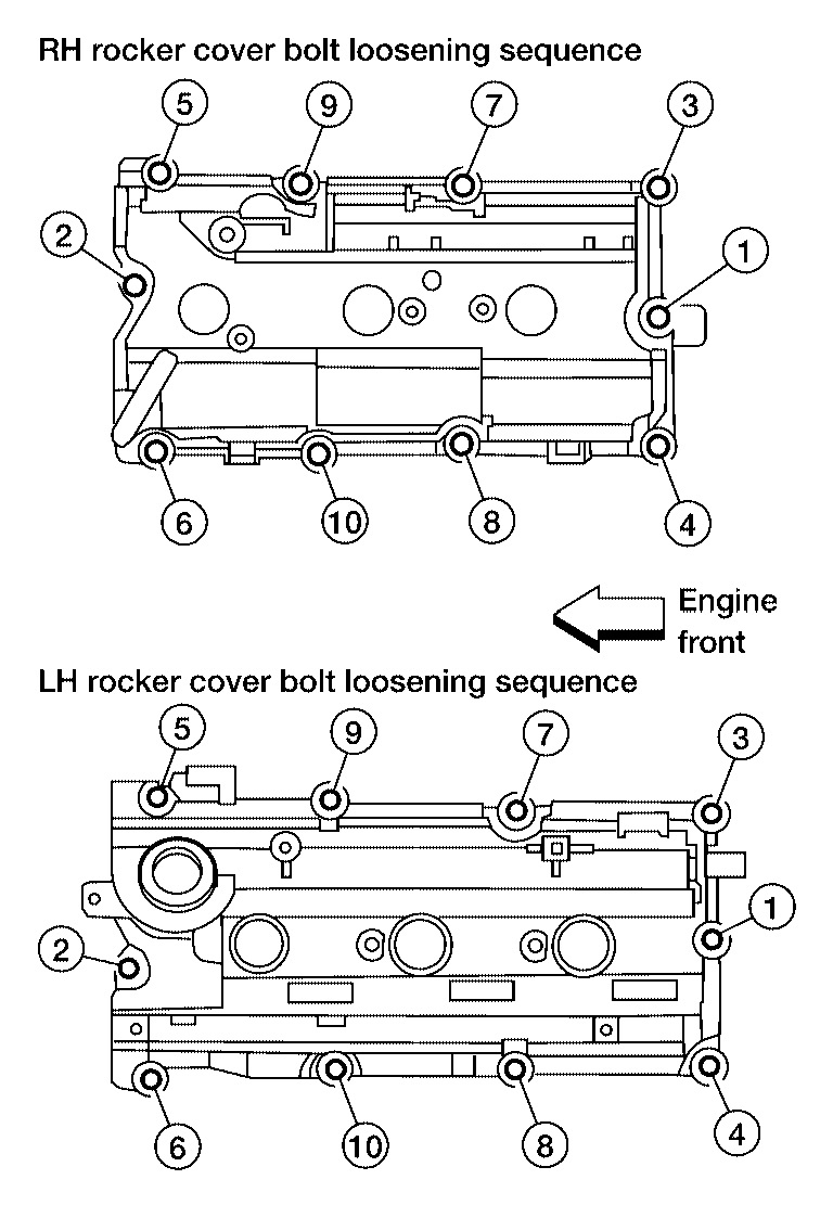
23. Remove the IVT control covers, right and left. Loosen the IVT control cover bolts in the order shown.
NOTE:
The shaft in the cover is inserted into the center hole of the intake camshaft sprocket. Remove the cover by pulling straight out until the cover disengages from the camshaft sprocket.
24. Remove the starter motor.
25. Remove the intake manifold collector.
Picture 4
26. Remove the six spark plugs.
NOTE:
Note locations for installation.
27. Remove the engine oil dipstick.
Picture 5
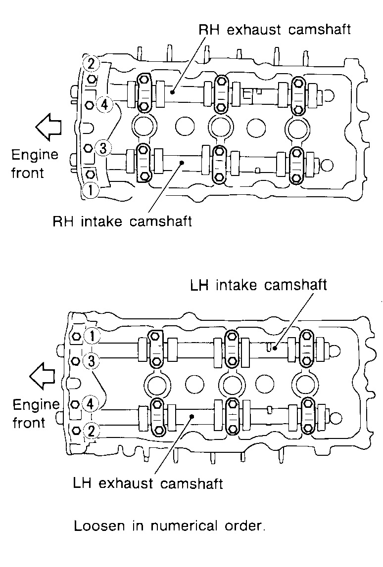
28. Remove the rocker covers. Loosen the rocker covers bolts in the order shown.
Picture 6
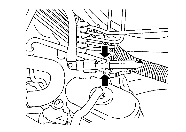
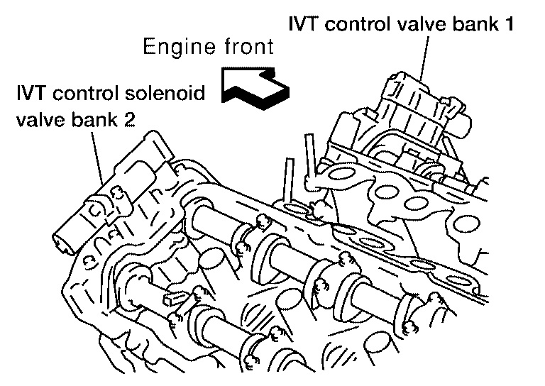
29. Remove the IVT control solenoid valves.
Discard the gaskets and use new gaskets for installation.
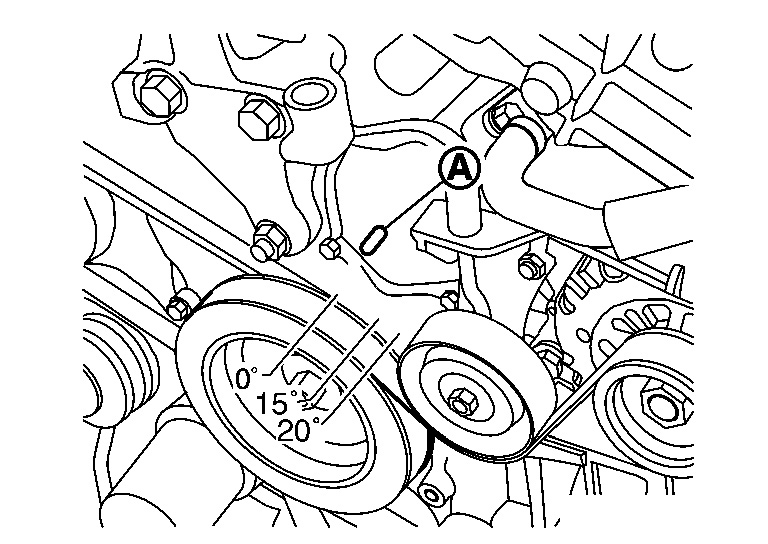
30. Obtain compression TDC of No. 1 cylinder as follows:
Picture 7
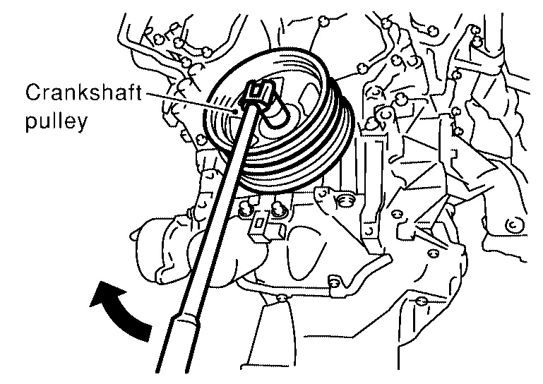
a. Rotate crankshaft pulley clockwise to align pointer (A) with TDC mark on crankshaft pulley.
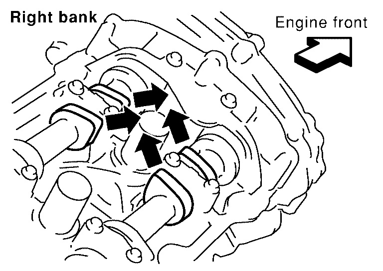
Picture 8
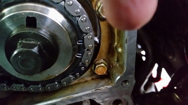
b. Check that intake and exhaust camshaft lobes on No. 1 cylinder (right bank of engine) are located as shown.
If not, turn the crankshaft one revolution (360°) and align as shown.
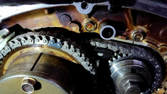
Picture 9
Picture 10
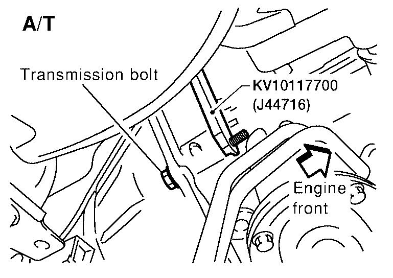
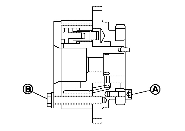
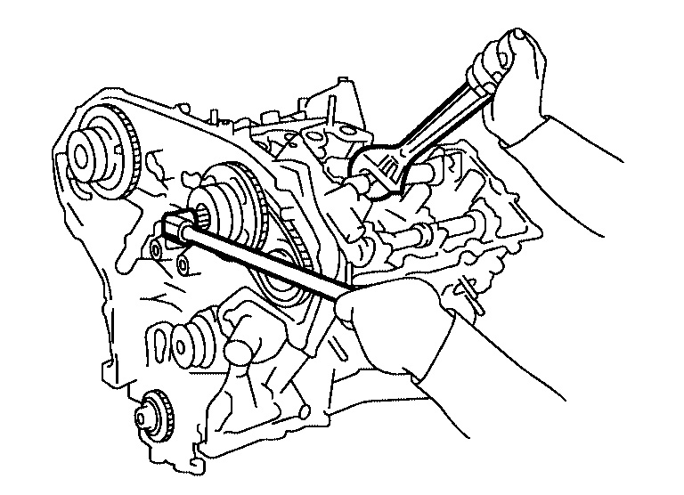
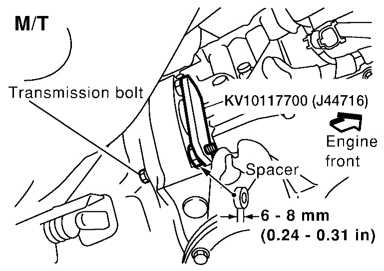
31. Install Tool as shown.
Tool number : KV10117700 (J44716)
CAUTION:
Do not damage the ring gear teeth, or the signal plate teeth behind the ring gear, when setting the stopper.
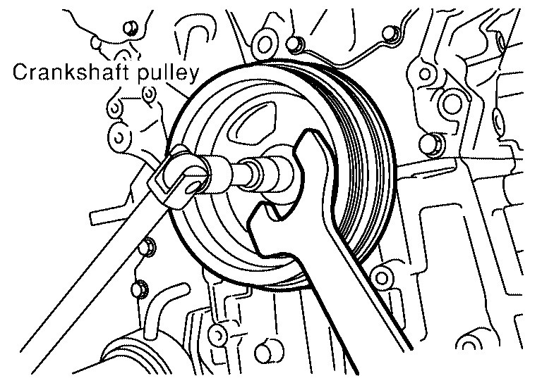
32. Remove the crankshaft pulley as follows:
Picture 11
a. Loosen crankshaft pulley mounting bolt using pulley holder and locate bolt seating surface at 10 mm (0.39 in) from its original position.
Picture 12
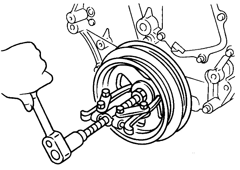
b. Position a pulley puller at recess hole of crankshaft pulley to remove crankshaft pulley.
CAUTION:
Do not use a puller claw on crankshaft pulley periphery.
Picture 13
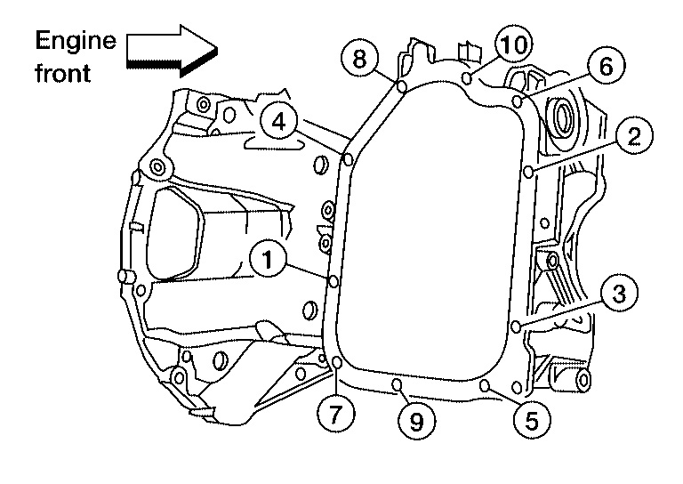
33. Loosen the lower oil pan bolts using power tool in order as shown.
34. Remove the lower oil pan.
Picture 14
a. Insert Tool between the lower oil pan and the upper oil pan.
Be careful not to damage the mating surface.
Do not insert a screwdriver, this will damage the mating surfaces.
B. Slide the Tool by tapping its side with a hammer to remove the lower oil pan from the upper oil pan.
Picture 15
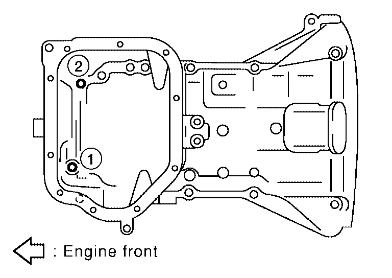
35. Loosen upper oil pan front bolts in order as shown.
36. If removing timing chain, temporarily install lower oil pan.
37. Support front of engine under oil pan using a jack.
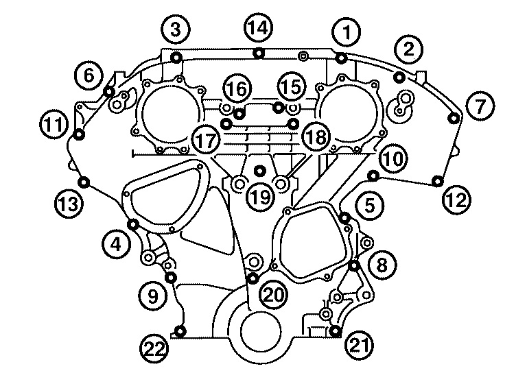
38. Remove the front timing chain case.
Picture 16
a. Remove the front timing chain case bolts in the order shown.
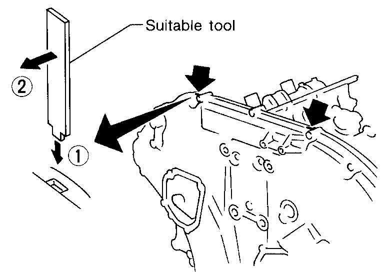
Picture 17
b. Insert the appropriate size tool into the notch (1) at the top of the front timing chain case as shown.
C. Pry off the case by moving the suitable tool (2) as shown.
Use seal cutter or an equivalent tool to cut liquid gasket for removal.
CAUTION:
Do not use a screwdriver or similar tool.
After removal, handle carefully so it does not bend, or warp under a load.
Picture 18
39. Remove the front oil seal from the front timing chain case using a suitable tool.
CAUTION:
Do not damage the front cover.
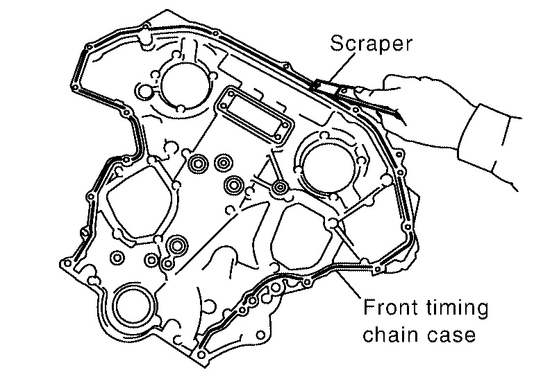
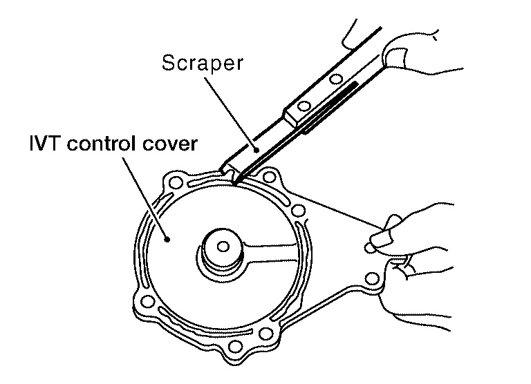
Picture 19
40. Use a scraper to remove all the old Silicone RTV Sealant from the front timing case and opposite mating surfaces.
CAUTION:
Do not damage the mating surfaces.
Picture 20
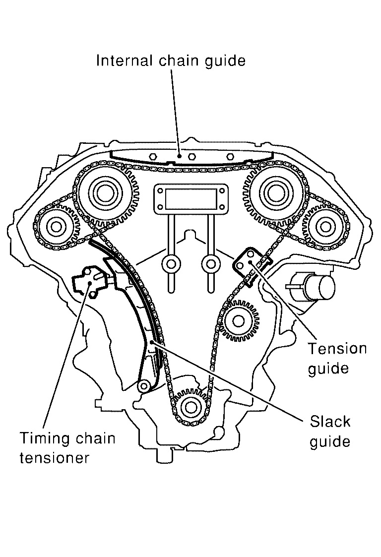
41. Remove the internal chain guide.
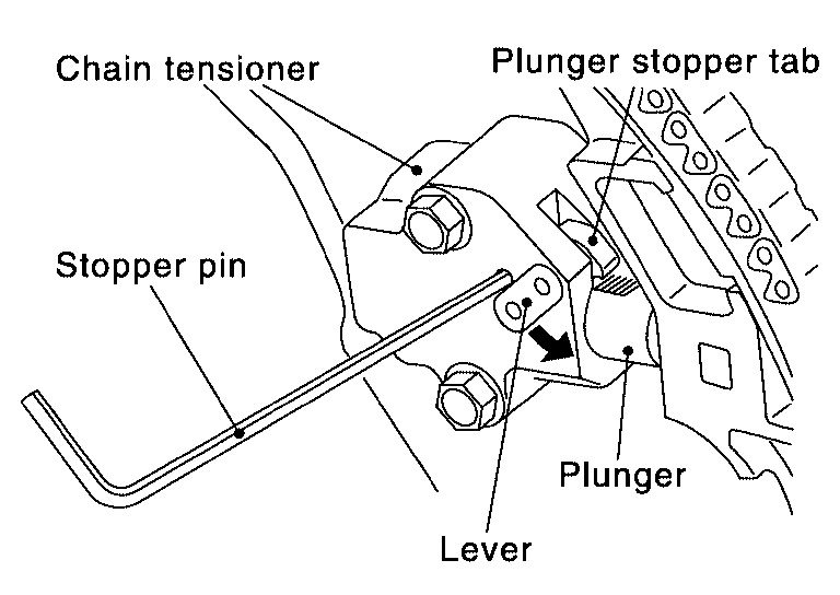
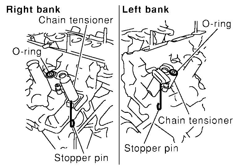
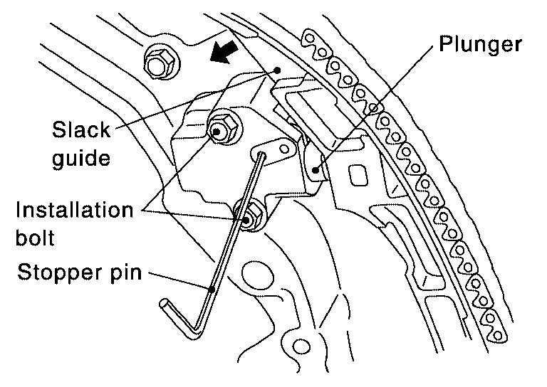
42. Remove the timing chain tensioner and slack guide.
Place paint marks on the timing chain and sprockets to indicate the correct position of the components for installation.
A. Pull lever down and release plunger stopper tab. Plunger stopper tab can be pushed up to release (coaxial structure with lever).
Picture 21
b. Insert stopper pin into tensioner body hole to hold lever, and keep the tab released. An Allen wrench [2.5 mm (0.098 in)] is used for a stopper pin as an example.
C. Insert plunger into tensioner body by pressing the slack side chain guide.
Picture 22
d. Keep the slack side chain guide pressed and hold it by pushing the stopper pin through the lever hole and body hole.
E. Remove the timing chain tensioner installation bolts and remove the timing chain tensioner.
F. Remove slack guide installation bolt and the slack guide.
43. Remove primary timing chain and crankshaft sprocket.
CAUTION:
After removing timing chain, do not turn the crankshaft and camshaft separately, or the valves will strike the pistons.
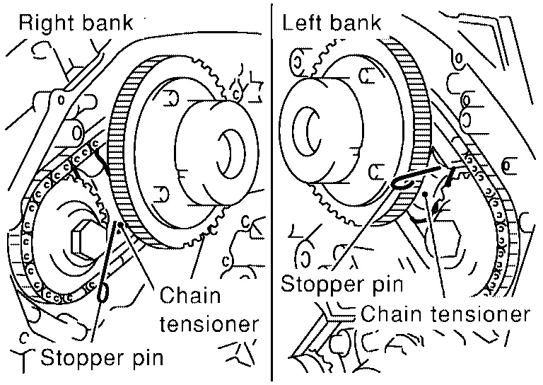
Picture 23
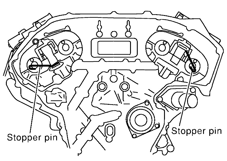
44. Attach a suitable stopper pin to the right and left camshaft chain tensioners (for secondary timing chains).
Picture 24
45. Remove the intake and exhaust camshaft sprocket bolts.
Apply paint to the timing chain and camshaft sprockets for alignment during installation.
Secure the hexagonal portion of the camshaft using a wrench to loosen the bolts as shown.
46. Remove the secondary timing chains with camshaft sprockets.
A. Rotate camshaft slightly, and slacken timing chain of timing chain tensioner side.
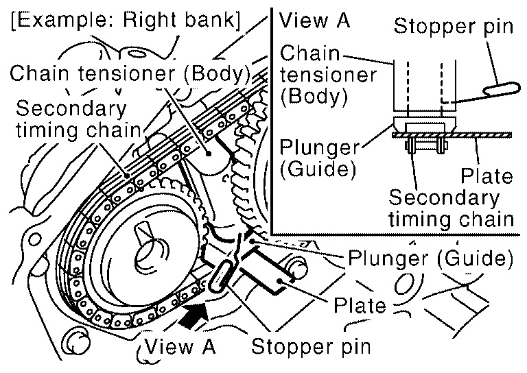
Picture 25
b. Insert metal or resin plate [0.5 mm (0.020 in)] into guide between timing chain and chain tensioner plunger. Remove cam sprocket and secondary timing chain with timing chain removed from guide groove.
Intake camshaft sprocket is two-for-one structure of primary and secondary sprockets.
Handle the intake sprockets as an assembly.
CAUTION:
Chain tensioner plunger can move while stopper pin is inserted in tensioner. Plunger can come out of tensioner when timing chain is removed. Use caution during removal.
Avoid impact or dropping the intake sprockets.
Picture 26
Do not disassemble the intake sprockets (never loosen bolts A and B as shown).
47. Remove the timing chain tension guide.
Picture 27
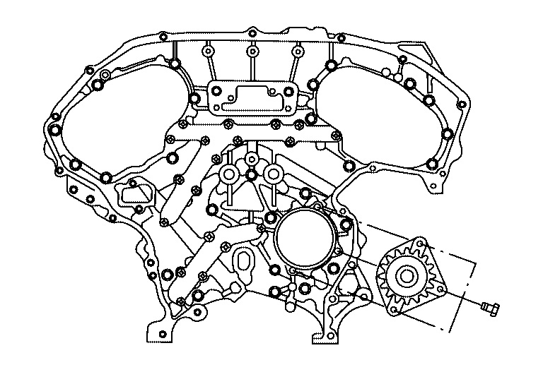
48. If neccesary remove the water pump.
49. If necessary, remove the rear timing chain case.
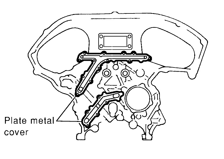
Picture 28
CAUTION:
Do not remove the plate metal cover for the oil passage.
After removing the chain case, do not apply any load to the case that might bend it.
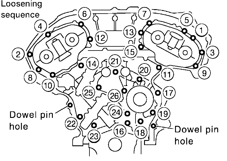
Picture 29
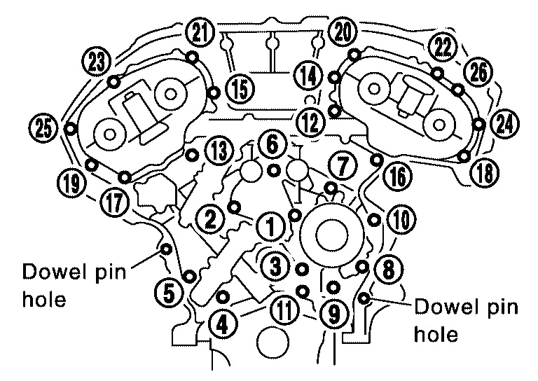
a. Loosen and remove the rear timing chain case bolts in the order shown.
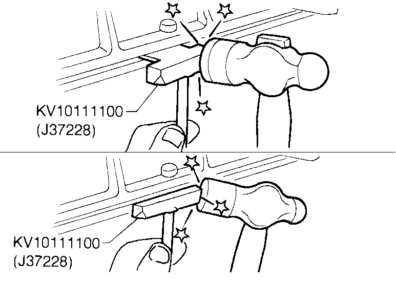
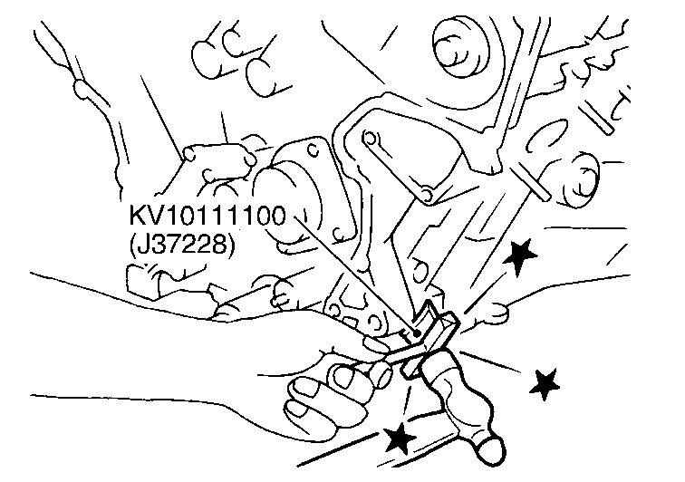
Picture 30
b. Cut the sealant using Tool and remove the rear timing chain case.
Tool number : KV10111100 (J37228)
50. Disconnect the inlet coolant hose.
51. Remove the inlet coolant housing, gasket and thermostat.
Picture 31
Picture 32
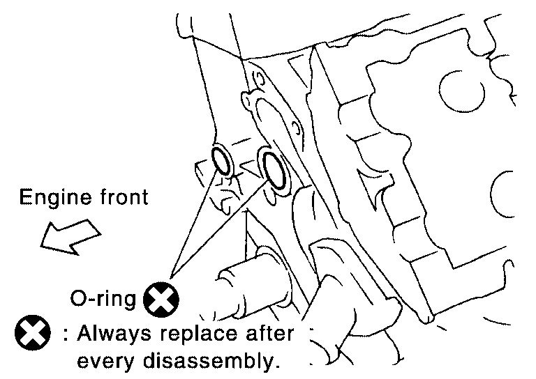
52. Remove O-rings on the cylinder head and cylinder block.
Picture 33
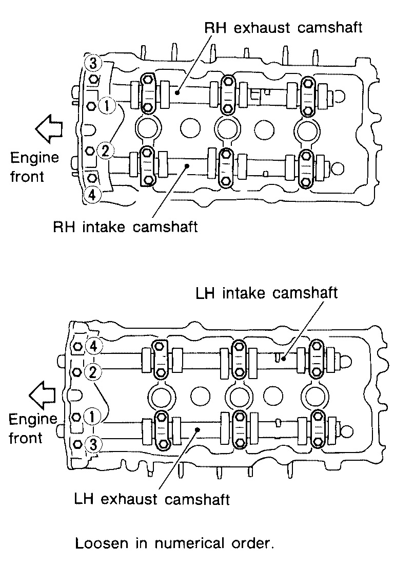
53. Loosen the No. 1 camshaft bracket bolts in several steps in the order shown and remove No. 1 camshaft brackets.
54. Remove the camshaft chain tensioners (for secondary timing chains).
Picture 34
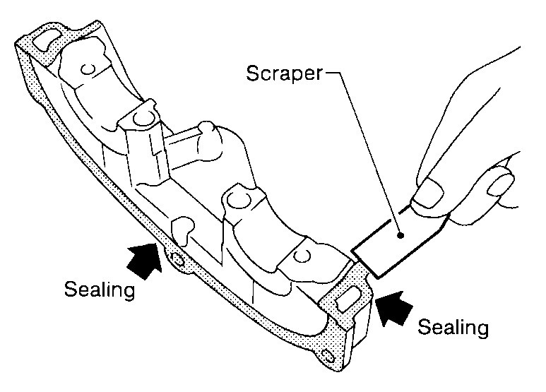
55. Use a scraper to remove all of the old Silicone RTV Sealant from the front and rear timing chain case and opposite mating surfaces.
CAUTION:
Do not damage the mating surfaces.
Picture 35
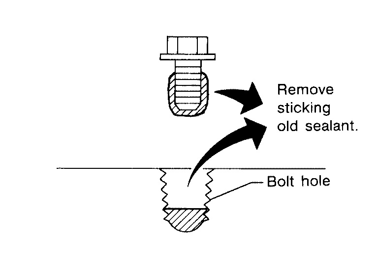
56. Remove all old Silicone RTV Sealant from all the bolt holes and bolts.
CAUTION:
Do not damage the threads or mating surfaces.
Picture 36
57. Use a scrapper to remove all of the old Silicone RTV Sealant from the water pump cover, chain tensioner cover and IVT control covers.
CAUTION:
Do not damage the threads or mating surfaces.
Picture 37
58. Remove the old Silicone RTV Sealant from the camshaft No. 1 bracket mating surface using a scraper.
Do not scratch or damage the mating surface.
Picture 38
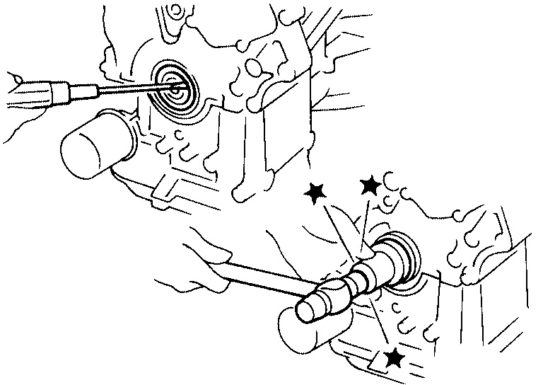
59. Remove the front seal from the front timing chain case using a suitable tool.
CAUTION:
Do not damage the front cover.
Picture 39
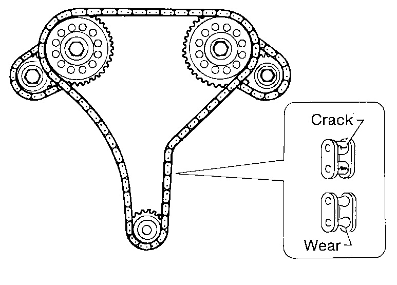
INSPECTION AFTER REMOVAL
Check for cracks and any excessive wear at the roller links of the timing chain. Replace the timing chain as necessary.
________________________________________________
Install
INSTALLATION
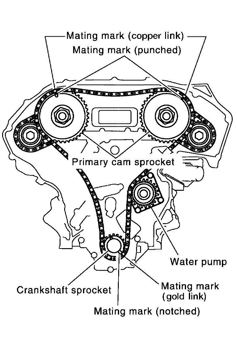
NOTE:
The figure shows the relationship between the mating mark on each timing chain and that on the corresponding sprocket, with the components installed.
Picture 40
1. Internal chain guide
2. Camshaft sprocket (intake)
3. Mating mark (copper link)
4. Mating mark (punched)
5. Secondary timing chain tensioner
6. Mating mark (gold link)
7. Secondary timing chain
8. Camshaft sprocket (exhaust)
9. Tensioner guide
10. Water pump
11. Crankshaft sprocket
12. Mating mark (notched)
13. Primary timing chain
14. Slack guide
15. Primary timing chain tensioner
16. Mating mark (back side)
17. Crankshaft key
Picture 41
1. Install the camshaft chain tensioners (for secondary timing chains).
Camshaft chain tensioner bolts
: 8.5 (0.87 kg-m, 75 in-lb)
Picture 42
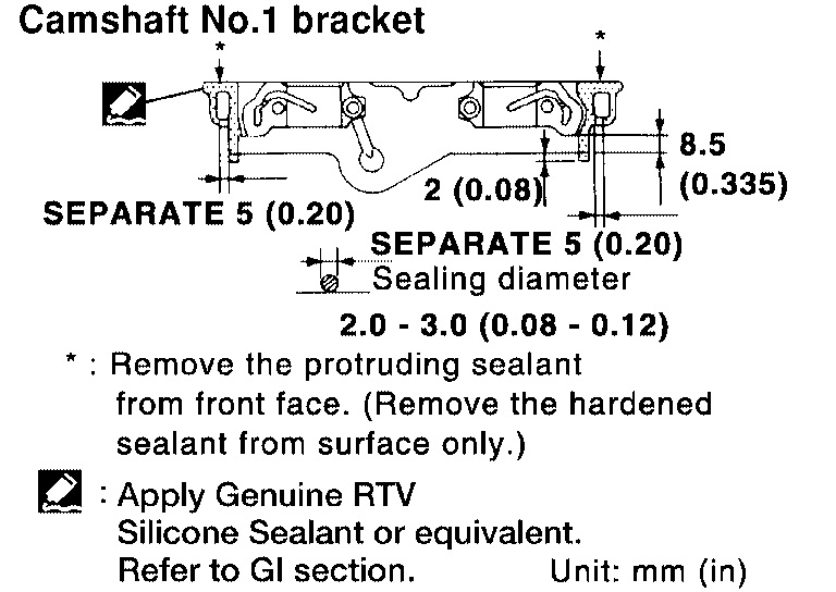
2. Before installing No. 1 camshaft bracket, apply sealant to mating surface.
Use Genuine Silicone RTV Sealant, or equivalent.
Before installation, wipe off any protruding sealant.
Picture 43
3. Tighten the No. 1 camshaft bracket in three steps, in the order shown.
Camshaft bracket bolts
Step 1 : 1.96 N.M (0.2 kg-m, 17 in-lb)
Step 2 : 6 N.M (0.6 kg-m, 52 in-lb)
Step 3 : 8.30 - 10.3 N.M (0.90 - 1.00 kg-m, 74 - 91 in-lb)
4. Install the thermostat, gasket and coolant inlet housing.
Coolant inlet housing bolts
: 8.4 - 11.2 N.M (0.86 - 1.14 kg-m, 74.6 - 99.0 in-lb)
5. Install rear timing chain case as follows:
Picture 44
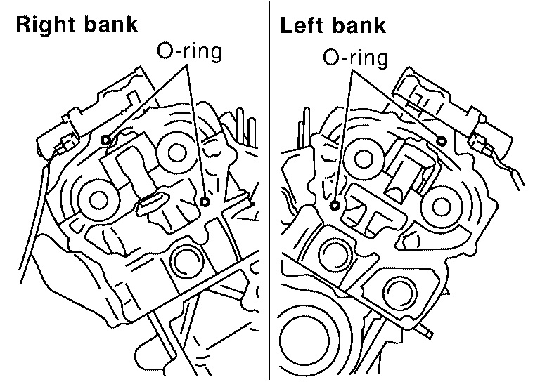
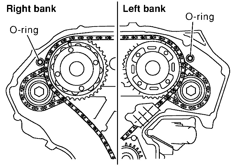
a. Install new O-rings on cylinder block.
Picture 45
b. Install new O-rings on cylinder head.
Picture 46
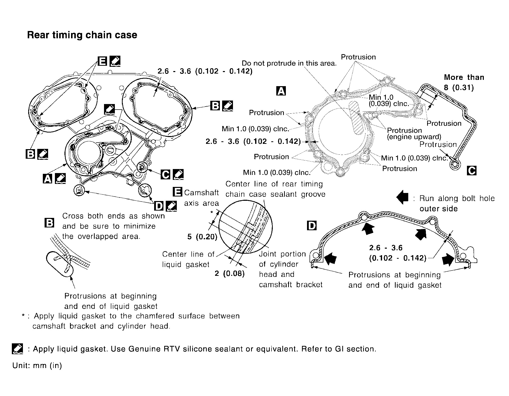
6. Apply Silicone RTV Sealant to rear timing chain case as shown.
Use Genuine Silicone RTV Sealant, or equivalent.
Before installation, wipe off the protruding sealant.
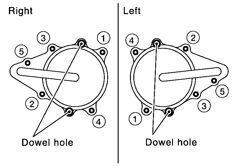
7. Align the rear timing chain case with the dowel pins (RH and LH) on the cylinder block and install the case. Make sure the O-rings stay in place during installation.
A. Loosely install the rear timing chain case in the order shown. There are two bolt lengths used. Follow the chart below for proper bolt length specifications.
Bolt position
1, 2, 3, 6, 7, 8, 9, 10
Bolt length
20 mm (0.79 in)
Bolt position
4, 5, 11 - 26
Bolt length
16 mm (0.63 in)
Picture 47
b. After all bolts are initially tightened, retighten them in the order shown.
Rear timing chain case
: 12 - 13 N.M (1.2 - 1.4 kg-m, 9 -10 ft-lb)
8. After installing rear timing chain case, check surface height difference between the rear timing chain case to cylinder block.
Standard
: - 0.24 - 0.14 mm (-0.0094 - 0.0055 in)
If not within standard, repeat above installation procedure.
9. Install the timing chain tension guide.
Timing chain tension guide bolts
: 19.6 - 23.5 N.M (2.0 - 2.3 kg-m, 15 -17 ft-lb)
10. Position the crankshaft so No. 1 piston is set at TDC on the compression stroke.
Picture 48
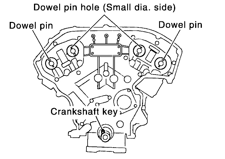
Make sure that the dowel pin hole, dowel pin and crankshaft key are located as shown.
Camshaft dowel pin hole (intake side): at cylinder head upper face side in each bank.
Camshaft dowel pin (exhaust side): at cylinder head upper face side in each bank.
Crankshaft key: at cylinder head side of RH bank.
CAUTION:
Hole on small diameter side must be used for intake camshaft sprocket dowel pin. Do not misidentify (ignore big diameter side).
Picture 49
11. If necessary, install the water pump and water pump bolts.
Water pump bolts
: 8.5 - 10.7 N.M (0.86 - 1.10 kg-m, 75-95 in-lb)
12. Install the secondary timing chains and camshaft sprockets.
CAUTION:
Matching marks between the timing chain and sprockets slip easily. Confirm all matching mark positions repeatedly during the installation process.
Picture 50
Push the sleeve of the secondary chain tensioner and keep it pressed in with a stopper pin.
Picture 51
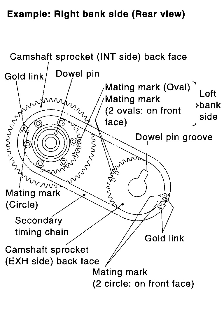
a. Align the matching marks on the secondary timing chain (gold link) with the ones on the intake and exhaust sprockets (stamped), and install them.
Matching marks for the intake sprocket are on the back side of the secondary sprocket.
There are two types of matching marks, round and oval types. They should be used for the RH and LH banks, respectively.
RH bank: use round type.
LH bank: use oval type.
B. Align the dowel pin and pin hole on the camshaft with the groove and dowel pin on the sprocket, and install them.
On the intake side, align the pin hole on the small diameter side of the camshaft front end with the dowel pin on the back side of the camshaft sprocket, and install them.
On the exhaust side, align the dowel pin on the camshaft front end with the pin groove on the camshaft sprocket, and install them.
Camshaft sprocket bolts must be tightened in the next step. Tightening them by hand is enough to prevent the dislocation of the dowel pins.
Picture 52
It may be difficult to visually check the dislocation of mating marks during and after installation. To make the matching easier, make a mating mark on the sprocket teeth in advance with paint.
13. After confirming the mating marks are aligned, tighten the camshaft sprocket bolts.
Picture 53
Secure the camshaft using a wrench at the hexagonal portion to tighten the camshaft sprocket bolts.
Camshaft sprocket bolts
: 98 - 107 N.M (10.5 - 10.9 kg-m, 73 - 78 ft-lb)
Picture 54
14. Pull the stopper pins out from the timing chain tensioners (for secondary timing chains).
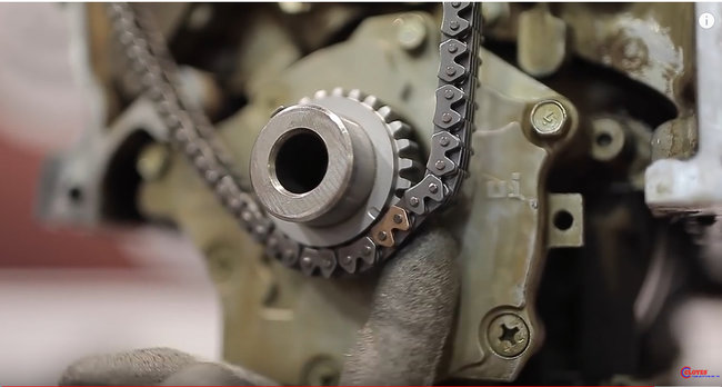
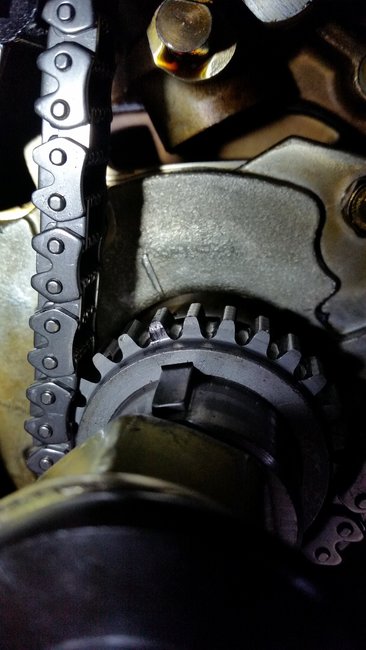
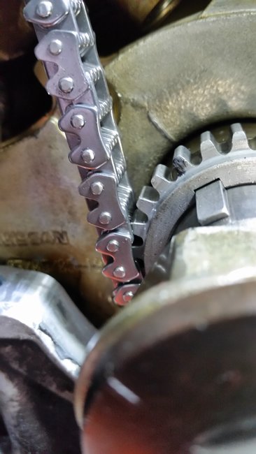
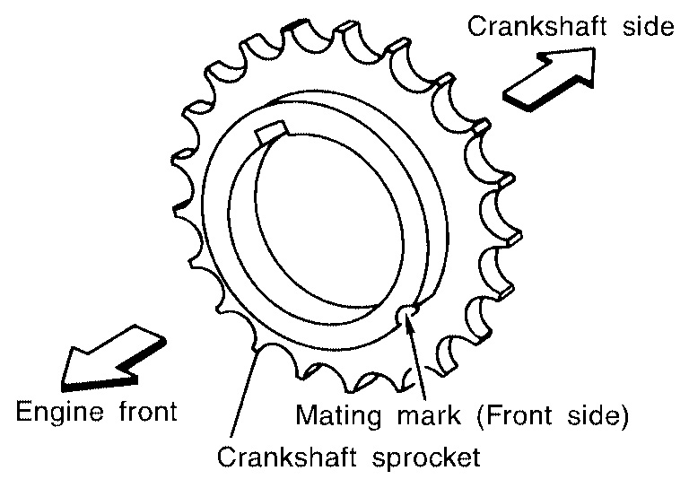
15. Install the crankshaft sprocket on the crankshaft.
Picture 55
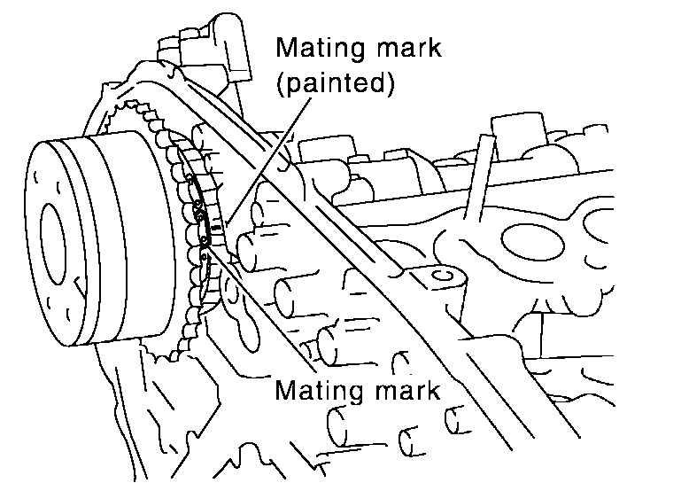
Make sure the mating marks on the crankshaft sprocket face the front of the engine.
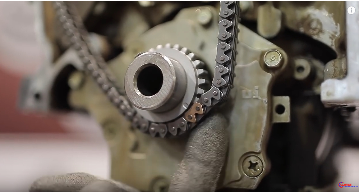
16. Install the primary timing chain.
Pic 56
Install primary timing chain so the mating mark (punched) on camshaft sprocket is aligned with the copper link on the timing chain, while the mating mark (notched) on the crankshaft sprocket is aligned with the gold link on the timing chain, as shown.
When it is difficult to align mating marks of the primary timing chain with each sprocket, gradually turn the camshaft using a wrench on the hexagonal portion to align it with the mating marks.
During alignment, be careful to prevent dislocation of mating mark alignments of the secondary timing chains.
Picture 57
17. Install the internal chain guide.
Internal chain guide bolts
: 6.9 N.M (0.70 - 0.95 kg-m, 61 - 82 in-lb)
Picture 58
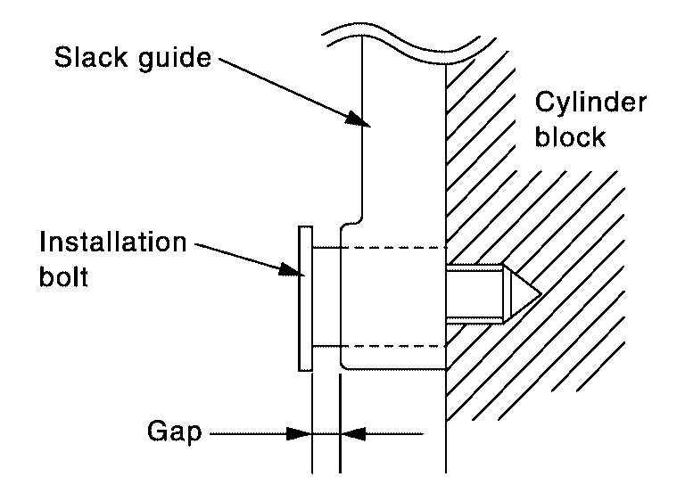
18. Install the slack guide.
Do not overtighten the slack guide installation bolt. It is normal for a gap to exist under the bolt seats when the installation bolt is tightened to specification.
Slack guide installation bolt
: 12.7 - 18.6 N.M (1.3 - 1.8 kg-m, 10 - 13 ft-lb)
19. Install the timing chain tensioner for the slack guide.
Timing chain tensioner installation bolts
: 6.9 - 9.3 N.M (0.70 - 0.95 kg-m, 61 - 82 in-lb)
Picture 59
When installing the chain tensioner, push in the sleeve and keep it pressed in with the stopper pin.
Remove any dirt and foreign materials completely from the back and the mounting surfaces of the chain tensioner.
After installation, pull out the stopper pin by pressing the slack guide.
20. Reconfirm that the matching marks on the sprockets and the timing chain have not slipped out of alignment.
Picture 60
21. Install new O-rings on the rear timing chain case.
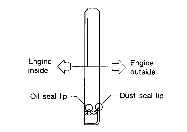
22. Install the front oil seal on the front timing chain case using a suitable tool. Apply clean engine oil to the oil seal edges.
Picture 61
Install it so that each seal lip is oriented as shown.
Suitable drift
Outer diameter : 59 mm (2.32 in)
Inner diameter : 49 mm (1.93 in)
CAUTION:
Press fit straight and avoid causing burrs or tilting the oil seal.
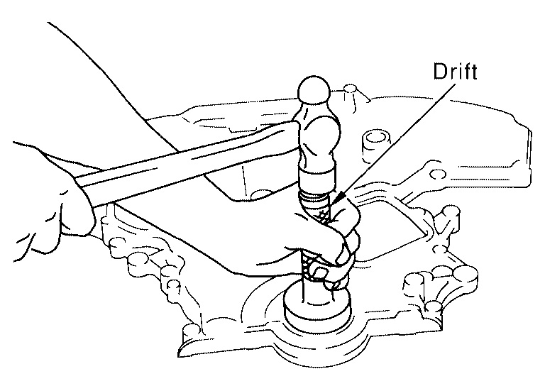
Picture 62
Using a suitable drift, press-fit oil seal until it becomes flush with timing chain case end face.
Make sure the garter spring in the oil seal is in position and seal lip is not inverted.
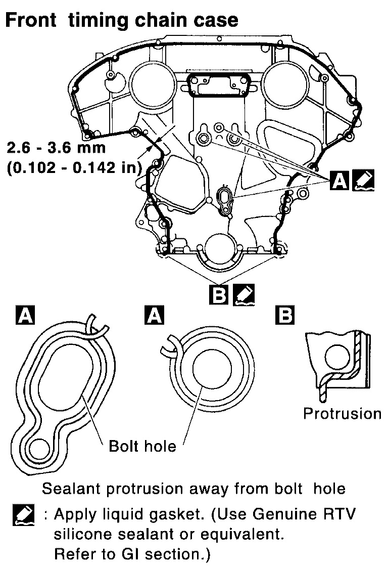
Picture 63
23. Apply Silicone RTV Sealant to front timing chain case as shown.
Use Genuine Silicone RTV Sealant, or equivalent.
Before installation, wipe off the protruding sealant.
Install dowel pin on the rear timing chain case into dowel pin hole in front timing chain case.
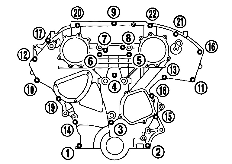
24. Loosely install the front timing chain case bolts.
Bolt position
1, 2
Bolt diameter
: 8 mm (0.31 in)
Bolt position
3 - 22
Bolt diameter
: 6 mm (0.24 in)
Picture 64
25. Tighten the front timing chain case bolts in the order shown.
Retighten the front timing chain case bolts in the order shown.
Bolt position
1, 2
Tightening specification
: 25.5 - 31.4 N.M (2.6 - 3.2 kg-m, 18.8 - 23.1 ft-lb)
Bolt position
3 - 22
Tightening specification
: 11.8 - 13.7 N.M (1.2 - 1.4 kg-m, 8.7 - 10.1 ft-lb)
Picture 65
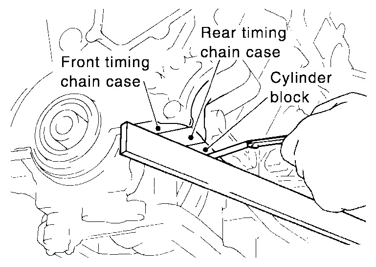
26. After installing the front timing chain case, check the surface height difference between the following parts on the oil pan mounting surface.
If not within specification, repeat the installation procedure.
Front timing chain case to rear timing chain case
: (-0.14) - 0.14 mm [(-0.0055) - (0.0055 in)]
Oil pump to cylinder block
: (-0.36) - (-0.10) mm [(-0.0142) - (-0.0039)in]
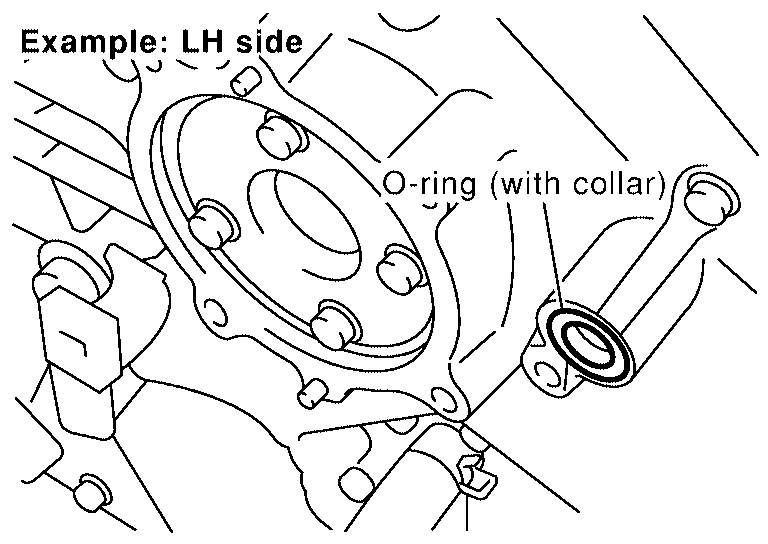
27. Install IVT control valve covers as follows:
Picture 66
a. Install new collared O-rings in front cover oil hole (LH and RH sides).
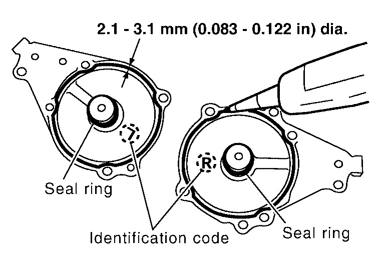
B. Install new seal rings on the IVT control covers.
Picture 67
c. Apply Silicone RTV Sealant to the IVT control covers.
Use Genuine Silicone RTV Sealant, or equivalent.
Being careful not to move the seal ring from the installation groove, align the dowel pins on the chain case with the holes to install the IVT control covers.
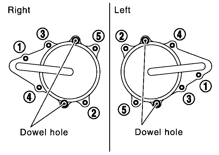
Picture 68
Tighten the intake valve timing control cover bolts in the order shown.
Intake valve timing control cover bolts
: 9.81 - 12.7 N.M (1.0 - 1.2 kg-m, 87 - 112 in-lb)
Picture 69
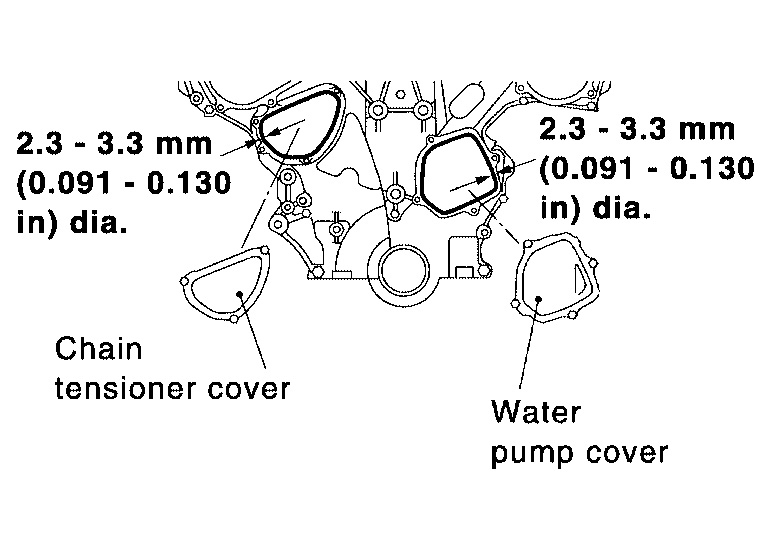
28. Apply liquid gasket and install the water pump cover and the chain tensioner cover.
Water pump cover bolts
: 10 - 12 N.M (1.0 - 1.3 kg-m, 87 - 112 in-lb)
Chain tensioner cover bolts
: 10 - 12 N.M (1.0 - 1.3 kg-m, 87 - 112 in-lb)
Use Genuine Silicone RTV Sealant or equivalent.
29. Install the RH engine mounting insulator, mount and bracket.
Picture 70
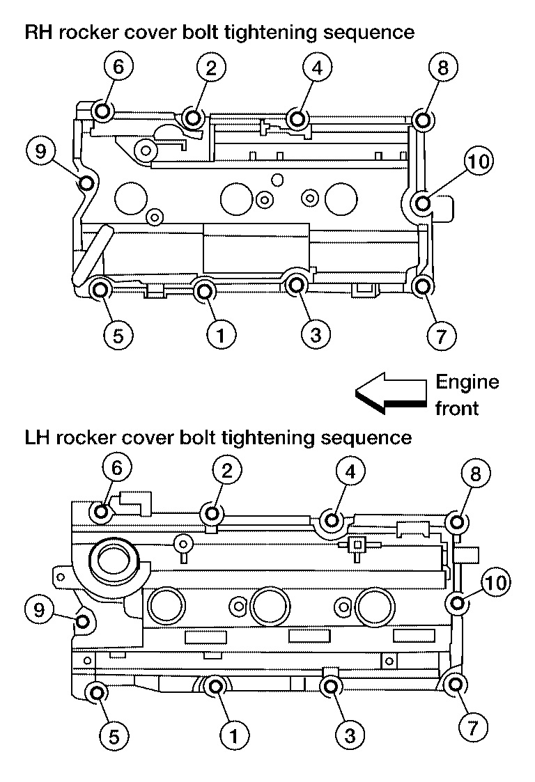
30. Install the RH and LH rocker covers. Tighten the rocker cover bolts in two steps in the order shown.
Step 1 : 0.96 - 2.96 N.M (0.1 - 0.3 kg-m, 9 - 26 in-lb)
Step 2 : 7.33 - 9.33 N.M (0.75 - 0.95 kg-m, 65 - 82 in-lb)
Picture 71
31. Install the IVT control solenoid valve bank 1 and bank 2.
IVT control solenoid valve bolts
: 10 - 12 N.M (1.0 - 1.3 kg-m, 87 - 112 in-lb)
32. Install the engine oil dipstick.
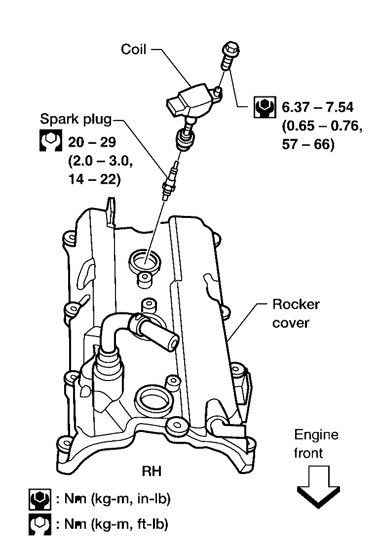
33. Install the six spark plugs in their original positions.
Spark plugs
: 20 - 29 N.M (2.0 - 3.0 kg-m, 14 - 22 ft-lb)
Picture 72
34. Install the six ignition coils in their original positions.
Ignition coils
: 6.37 - 7.54 N.M (0.65 - 0.76 kg-m, 57 - 66 in-lb)
35. Install the intake manifold collector.
Picture 73
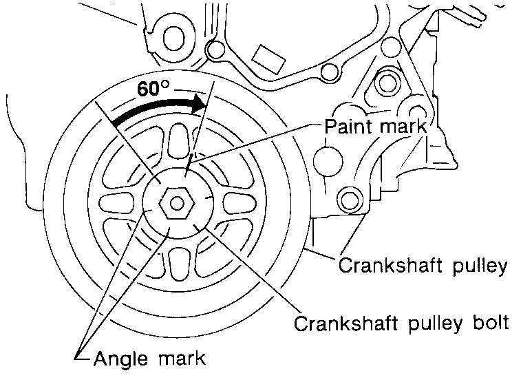
36. Install crankshaft pulley and tighten the bolt in two steps.
Picture 74
Lubricate thread and seat surface of the bolt with new engine oil.
Apply a paint mark for the second step of angle tightening.
Step 1
: 39 - 49 N.M (4.0 - 5.0 kg-m, 29 - 36 ft-lb)
Step 2
: 60° - 65° degrees clockwise
Picture 75
Picture 76
37. Remove Tool attached to the starter bolt hole.
Tool number : KV10117700 (J44716)
38. Install the starter motor.
39. Install the RH engine mounting insulator, mount and bracket.
40. Reposition and reconnect the engine harness.
41. Install the generator.
42. Install the upper and lower oil pans.
43. Install the power steering pump.
44. Install the A/C compressor and recharge the system.
45. Install the idler pulley and the drive belts.
46. Install the inner fender splash shield and the engine undercover.
47. Connect the inlet coolant hose.
48. Install the IPDM E/R and bracket.
49. Install the RH wheel and tire.
50. Install the windshield wiper assembly.
51. Install the cowl top grille.
52. Install the fuel hose quick connector to the fuel tube at the vehicle piping side.
53. Install the engine coolant reservoir.
54. Install the intake air duct with the air cleaner case lid and mass air flow sensor.
Picture 77
55. Install engine cover.
56. Refill the coolant.
CAUTION:
Wait at least 30 minutes for the Silicone RTV Sealant to set before filling the engine with fluids to avoid leaks.
57. Refill the engine oil.
CAUTION:
Wait at least 30 minutes for the Silicone RTV Sealant to set before filling the engine with fluids to avoid leaks.
58. Connect the battery negative terminal.
59. Activate the fuel system. Check for any leaks when the system is repressurized and correct as necessary.
60. Start the engine and check all systems for leaks or improper operation. Correct as necessary.
After starting engine, keep idling for three minutes. Then rev engine up to 3,000 rpm under no load to purge air from the high-pressure oil chamber of the chain tensioners. The engine may produce a rattling noise. This indicates that air still remains in the chamber and is not a matter of concern.
Images (Click to make bigger)
Thursday, February 25th, 2021 AT 11:41 AM