Good afternoon,
Unfortunately, you just caused a whole lot more issues with adding that stop leak. That stuff is no good at all and ruins the seals in the rack and the pump.
At this point, you need to replace the pump and the rack itself. The seals in the pump are most likely damaged as well.
https://www.2carpros.com/articles/how-to-replace-a-power-steering-pump
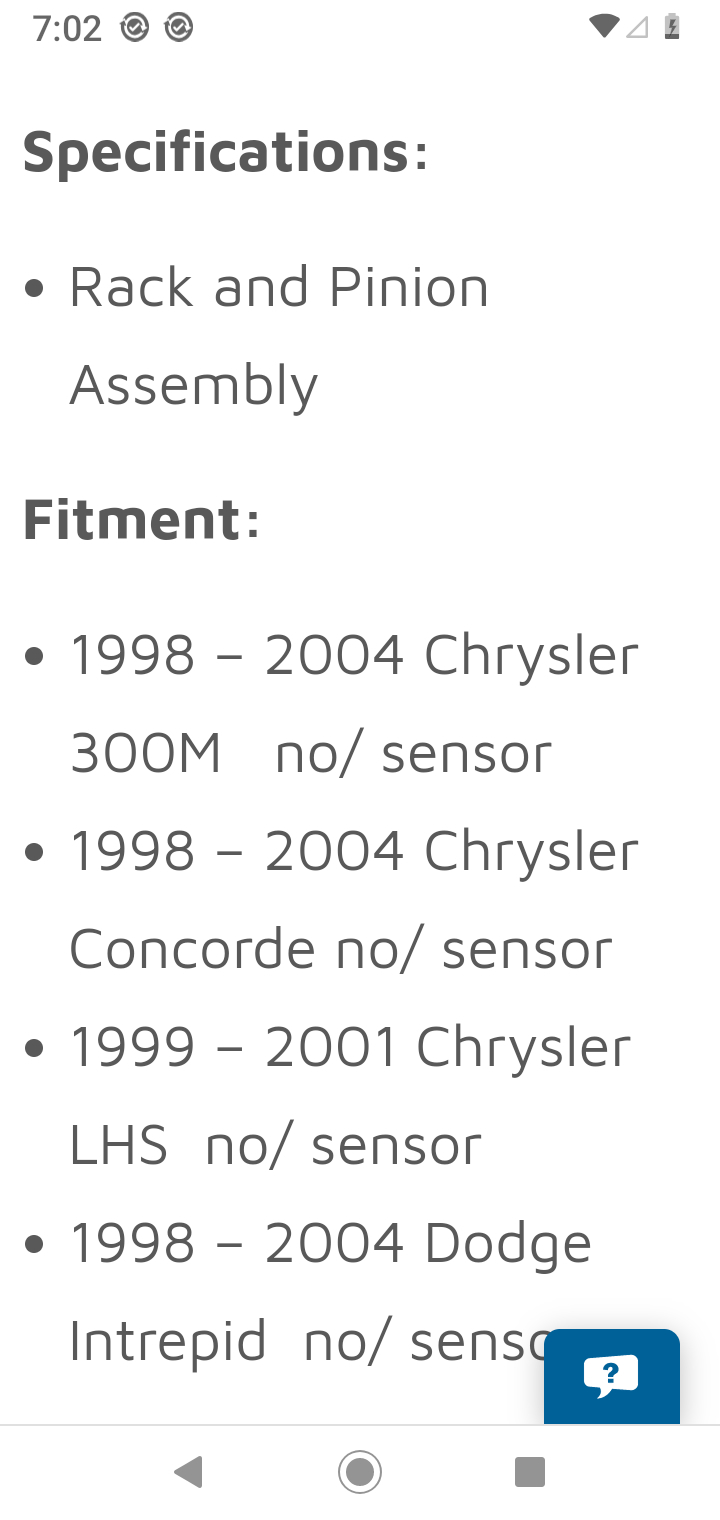
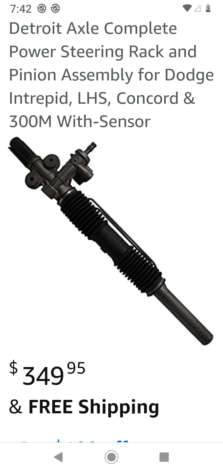
With the replacement rack, you will need new bolts for the tie rod ends. Fastenall will carry them for you as they are special. Take one of them with you to match up.
Once you get the new rack and pump installed, then have it aligned to be sure the front end is correct.
https://www.2carpros.com/articles/power-steering-fluid-flush
Roy
Pump
REMOVE
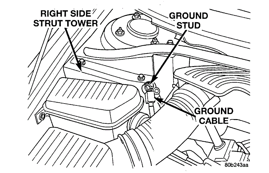
1. Remove the battery ground cable from the ground stud on the shock tower. Then correctly isolate the ground cable by installing the cable isolator on the ground stud.
NOTE: The following step should be done to prevent excessive spilling of power steering fluid when the power steering fluid lines are removed from the power steering pump.
2. Using a siphon pump, remove as much power steering fluid as possible from the power steering fluid reservoir.
3. Raise vehicle.
imageOpen In New TabZoom/Print
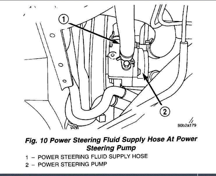
4. Remove the power steering fluid supply hose from the supply fitting on the power steering pump.
5. Let power steering fluid drain from the power steering fluid reservoir and power steering pump.
6. Install a cap on the open nipple of the power steering fluid reservoir to prevent power steering fluid from spilling when removing the power steering pump.
imageOpen In New TabZoom/Print
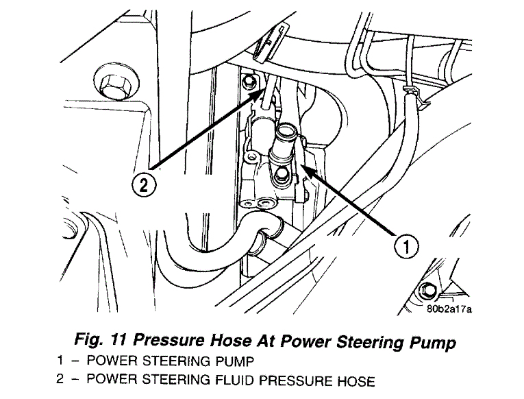
7. Remove the power steering fluid pressure hose from the pressure fitting on the power steering pump.
8. Let remaining power steering fluid drain from the power steering pump.
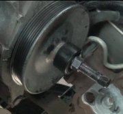
9. Remove the wiring harness connector from the power steering pressure switch located on the side of the power steering pump.
imageOpen In New TabZoom/Print
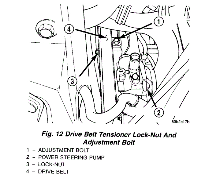
10. Loosen the lock-nut on the front of the pulley for the serpentine drive belt tensioner.
11. Using the adjustment bolt remove the tension from the drive belt for the power steering pump.
12. Remove the drive belt from the power steering pump pulley.
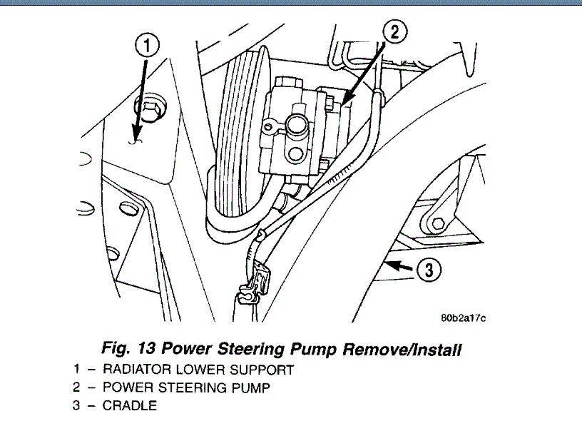
NOTE: Access for the power steering pump mounting bolts is through the holes in the face of the power steering Pump pulley.
13. Remove the 3 bolts attaching the power steering pump to the power steering pump mounting bracket.
imageOpen In New TabZoom/Print
14. Remove the power steering pump from the engine. The power steering pump and pulley are removed as an assembly from the engine. The power steering pump is removed from the bottom of the engine between the radiator lower support and the cradle.
15. Transfer the required parts from the removed power steering pump, to the replacement power steering pump.
INSTALL
1. Install the power steering pump back in the mounting bracket using the reverse sequence of its removal.
2. Loosely install all 3 bolts mounting the power steering pump to the mounting bracket.
3. Tighten the power steering pump mounting bolts to a torque of 28 Nm (260 inch lbs.).
4. Install the drive belt on the power steering pump pulley. Refer to Engine, for required installation and tensioning procedure for the particular engine being serviced.
5. Securely tighten the lock-nut on the pulley of the drive belt tensioner.
6. Install the wiring harness connector on the power steering pressure switch.
7. Install the power steering pressure hose on the pressure fitting of the power steering pump. Tighten the power steering fluid pressure hose fitting to a torque of 47 Nm (35 ft. lbs.).
8. Install the power steering fluid supply hose onto the supply fitting on power steering pump. When installing the hose clamp on the power steering fluid return hose be sure the clamp is installed past the upset bead on the nipple of the power steering fluid reservoir.
9. Lower vehicle.
10. Connect the battery ground cable onto the ground stud located on the strut tower.
CAUTION: Do not use automatic transmission fluid in this vehicles power steering system. Only use Mopar (R), Power Steering Fluid, or equivalent.
11. Fill the power steering pump reservoir to correct fluid level.
12. Start engine and turn steering wheel several times from stop to stop to bleed air from fluid in system. Stop engine, check fluid level, and inspect system for leaks. See Checking Fluid Level.
Rack
1. Remove the battery ground cable from the ground stud on the shock tower. Then correctly isolate the ground cable by installing the cable isolator on the ground stud.
2. Position the front tires of the vehicle so that they are facing straight ahead.
3. Raise the vehicle on a frame contact type hoist until the front tires of the vehicle are just off the floor.
imageOpen In New TabZoom/Print
4. Remove caps from both wiper arms at the attachment to the pivots to expose the wiper arm attaching nut. Remove the nut attaching each wiper arm to its pivot
5. Remove the wiper arms from the pivots. Wiper arms are removed from the pivots by rocking them back and force on the pivots until they can be pulled off the pivots.
imageOpen In New TabZoom/Print
6. Remove the wiper module cover and cowl cover from the vehicle.
Reinforcement Attachment To Vehicle
imageOpen In New TabZoom/Print
7. Remove the 8 bolts, attaching the reinforcement to the strut towers and the 1 bolt attaching the wiper module to the reinforcement. Remove the reinforcement from the vehicle.
In-Line Resonator And Air Inlet Hose
imageOpen In New TabZoom/Print
8. Remove the in-line resonator and inlet hose from the throttle body and air let hose coming from the lid of the air cleaner housing.
NOTE: When locking the steering wheel, the front tires of the vehicle are to be facing straight ahead.
imageOpen In New TabZoom/Print
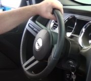
9. Using a steering wheel clamp, lock the steering wheel from rotating.
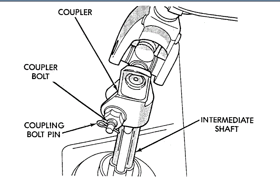
CAUTION: Before removing the steering column coupler from the intermediated steering shaft be sure the steering wheel is locked from rotating. If the steering wheel is allowed to rotate freely after it is disconnected from the intermediated shaft, the clockspring will be damaged and will need to be replaced.
imageOpen In New TabZoom/Print
10. Remove the retaining pin and the coupler bolt from the steering column coupler. Separate the intermediate steering shaft from the steering column coupler.
imageOpen In New TabZoom/Print
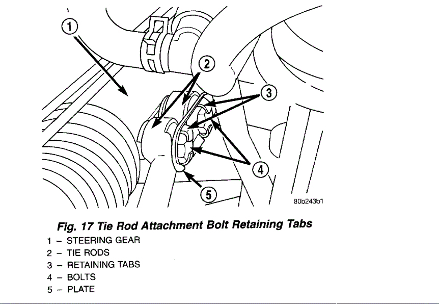
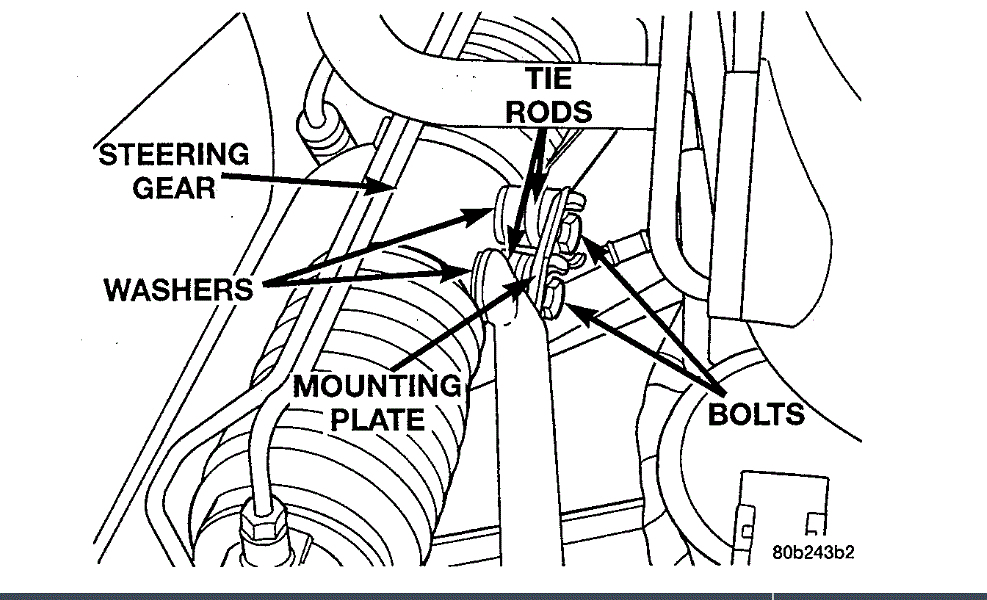
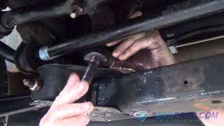
11. Bend back the retaining tabs on the mounting plate for the tie rod to steering gear mounting bolts.
Tie Rod To Steering Gear Attaching Bolts
imageOpen In New TabZoom/Print
12. Remove the bolts, mounting plate and washers attaching the tie rods to the steering gear. Lay the tie rods on top of the trans-axle bell housing.
NOTE: The following step should be done to prevent excessive spilling of power steering fluid when the power steering fluid lines are removed from the steering gear.
13. Using a siphon pump, remove as much power steering fluid as possible from the power steering fluid reservoir.
imageOpen In New TabZoom/Print
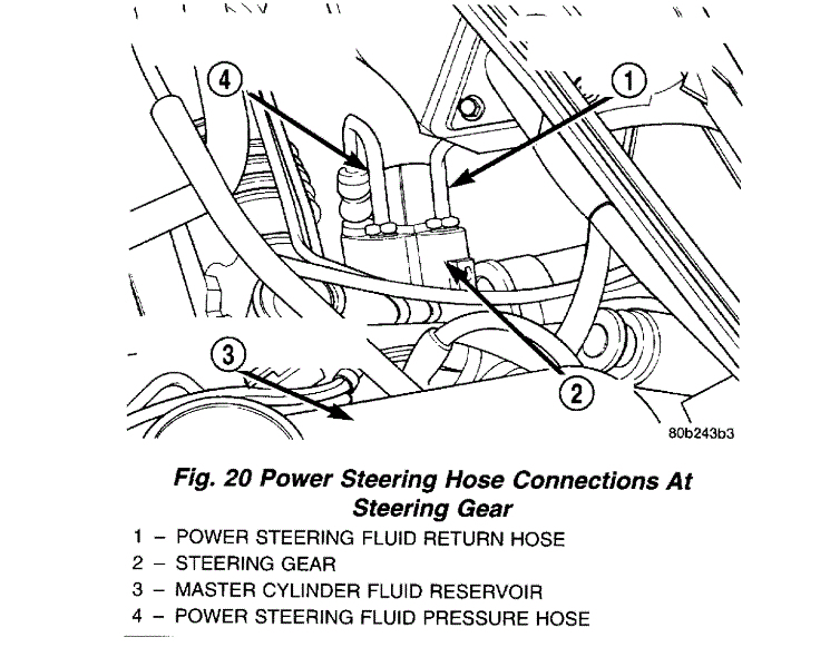
14. Remove the power steering fluid pressure hose and return hose from the steering gear.
Wiring Harness Connection To Solenoid
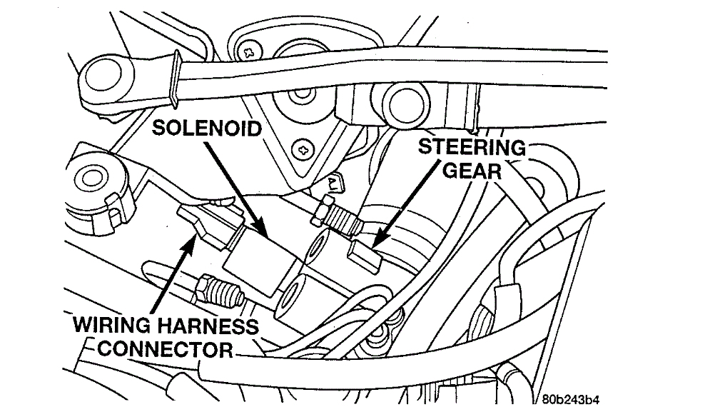
imageOpen In New TabZoom/Print
15. If the steering gear being removed from the vehicle is a speed proportional steering gear, remove the wiring harness connector from the solenoid on the steering gear.
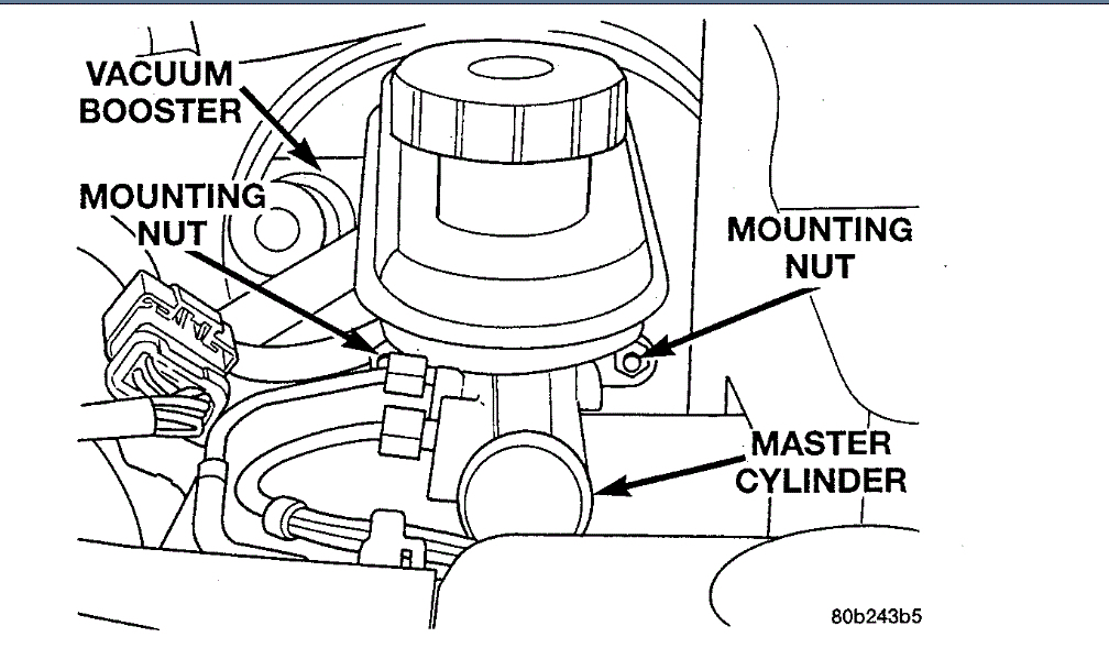
Master Cylinder To Vacuum Booster Mounting
imageOpen In New TabZoom/Print
16. Remove the 2 nuts mounting the master cylinder to the vacuum booster.
17. Remove the master cylinder with the brake tubes connected, from the vacuum booster. Carefully position the master cylinder in an upright position on the left side valve cover of the engine.
18. Remove the vacuum supply hose to the vacuum booster at the check valve in the vacuum booster. Position the vacuum hose out of the way.
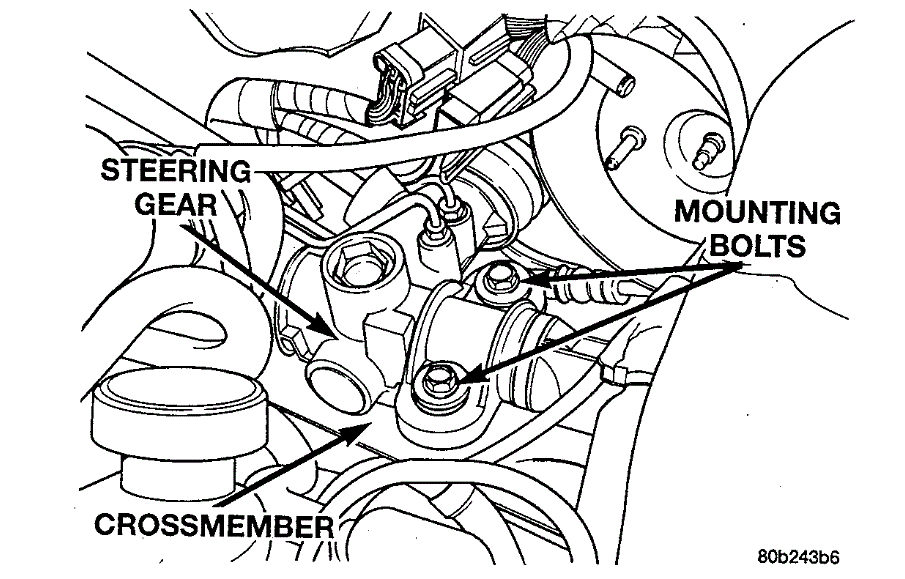
Steering Gear Attachment To Cross-member (Left Side)
imageOpen In New TabZoom/Print
19. Remove the 2 bolts attaching the left side of the steering gear to the cross-member.
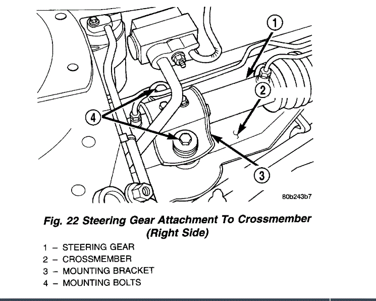
imageOpen In New TabZoom/Print
20. Remove the 2 bolts attaching the steering gears right side mounting bracket to the cross-member.
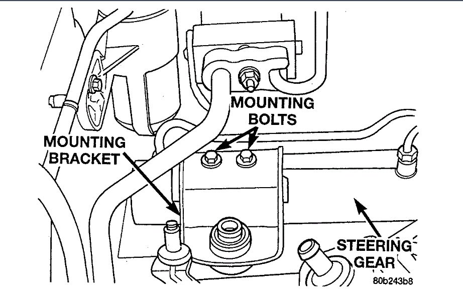
Steering Gear Mounting Bracket
imageOpen In New TabZoom/Print
NOTE: It may be necessary to loosen the 2 mounting bolts attaching the right mounting bracket to the steering gear in order to clear the air conditioning lines.
21. Slide steering gear and intermediate shaft forward into the engine compartment to allow access to the roll pin retaining the intermediate shaft flex coupler to the steering gear shaft.
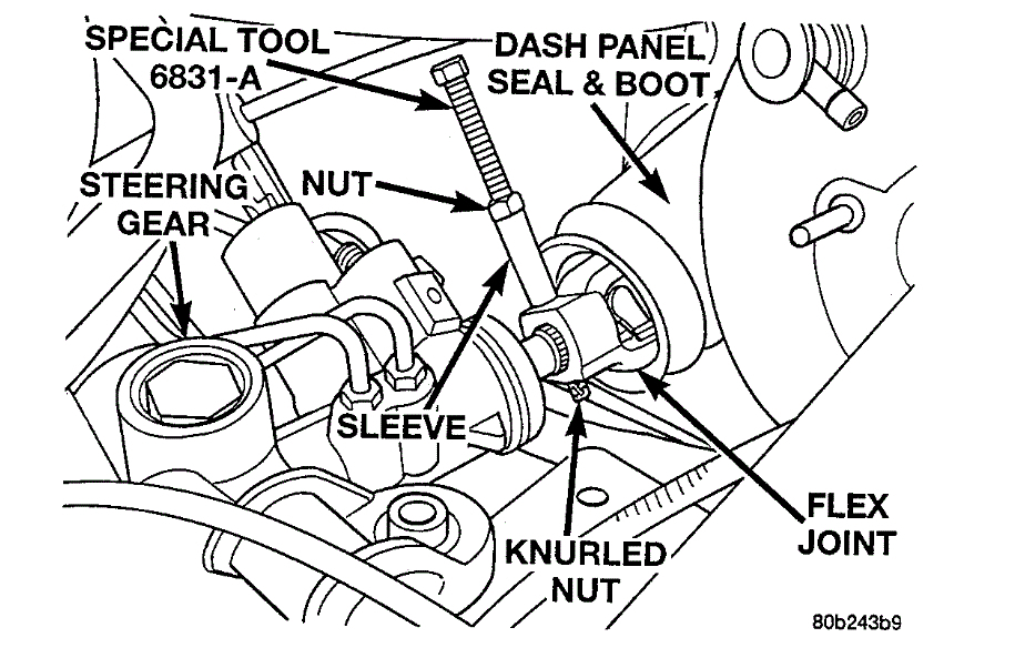
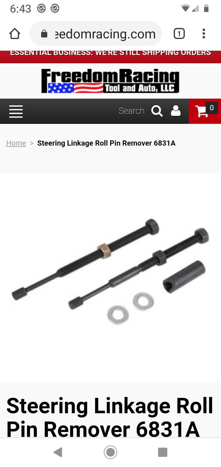
Steering Coupler Roll Pin Removal
imageOpen In New TabZoom/Print
22. Using roll pin remover, Special Tool 6831A, remove roll pin from flex joint of intermediate shaft. Roll pin is removed from coupler using following procedure. Remove knurled nut from small end of removal tool. Insert small end of removal tool through center of roll pin and then install and hand tighten knurled nut. Position sleeve of removal tool on flex joint as shown. Holding threaded shaft of tool from turning tighten nut pulling roll pin out of flex joint.
23. Separate the intermediate steering shaft from the steering gear.
24. Raise vehicle.
25. Remove the right front tire/wheel.
Tie Rod End Attachment To Strut
imageOpen In New TabZoom/Print
26. Remove the nut attaching the tie rod end to the steering arm on the right strut.
Removing Outer Tie Rod From Steering Arm
imageOpen In New TabZoom/Print
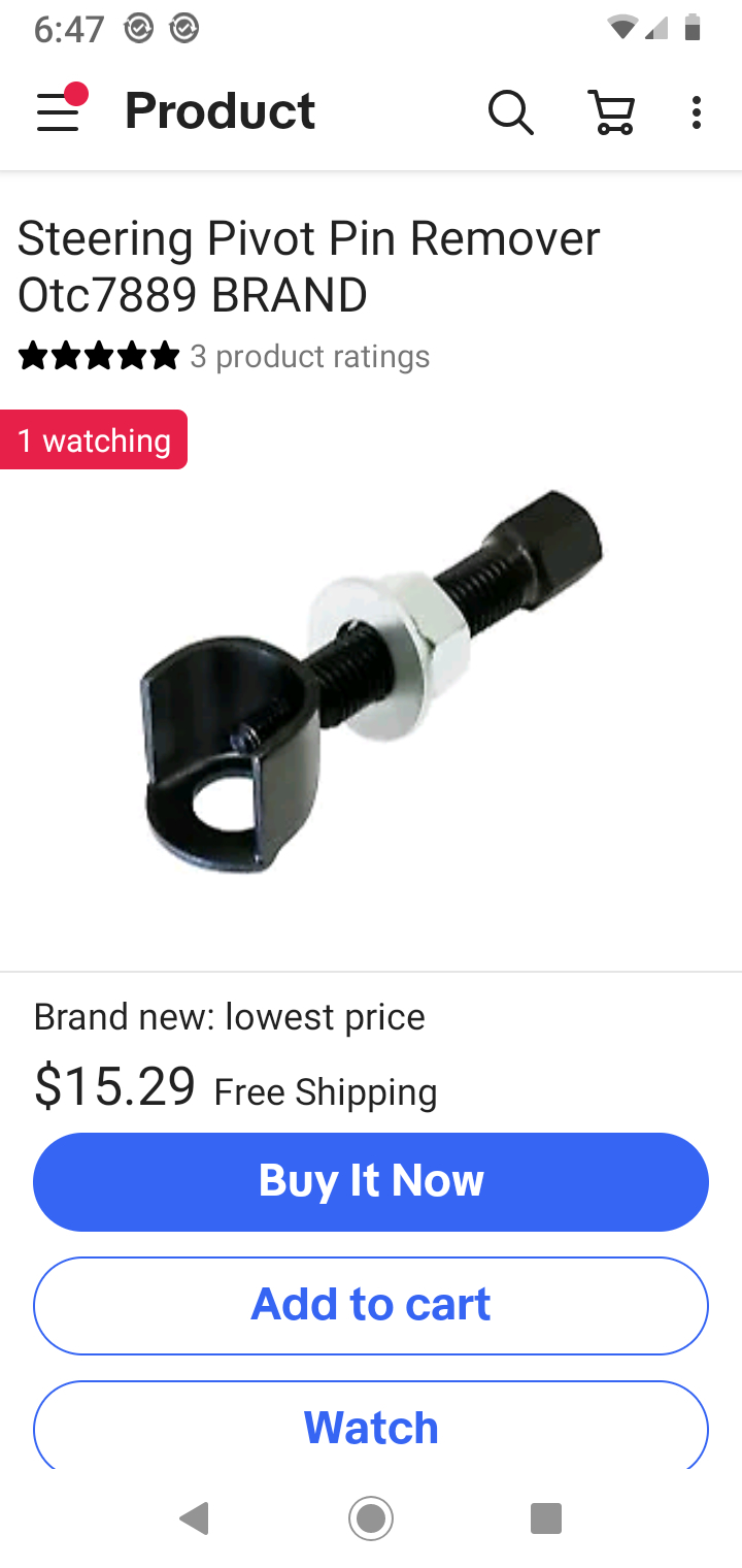
27. Remove the tie rod end from the steering arm of the strut using Puller, Special Tool C-3894-A, or equivalent.
28. Remove the tie rod from the vehicle.
Required Toe Position
imageOpen In New TabZoom/Print
NOTE: If the vehicle is equipped with a 2.7 liter engine, rotate the front of the left front tire/wheel as far outward as possible. This is necessary to have the required clearance to allow the removal of the steering gear from a vehicle with this engine application.
29. Remove the steering gear from the vehicle using the following steps.
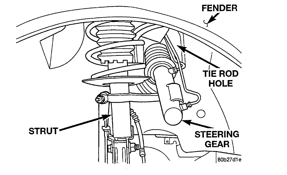
Steering Gear Through Tie Rod Hole
imageOpen In New TabZoom/Print
a. Slide the end of the steering gear through the tie rod hole in the right side inner fender. Steering gear needs to be slid through tie rod hole until about half of the steering gear is through the hole.
Steering Gear Positioned For Removal
imageOpen In New TabZoom/Print
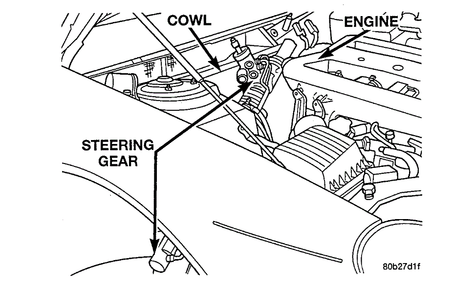
b. Lift the left end of the steering gear upward, with the steering gear positioned as shown, between the back of the engine and the front of the cowl.
c. To remove the steering gear from the vehicle, pull the steering gear toward the passenger side of the vehicle out from between the cowl and the engine.
Images (Click to make bigger)
Thursday, August 6th, 2020 AT 11:56 AM