Good afternoon,
If the relay energizes when you turn the key to start, you need to go to the starter solenoid and check for power at the yellow wire.
https://www.2carpros.com/articles/how-to-check-an-electrical-relay-and-wiring-control-circuit
https://www.2carpros.com/articles/how-to-check-a-car-fuse
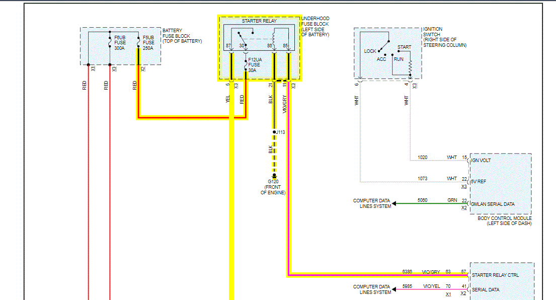
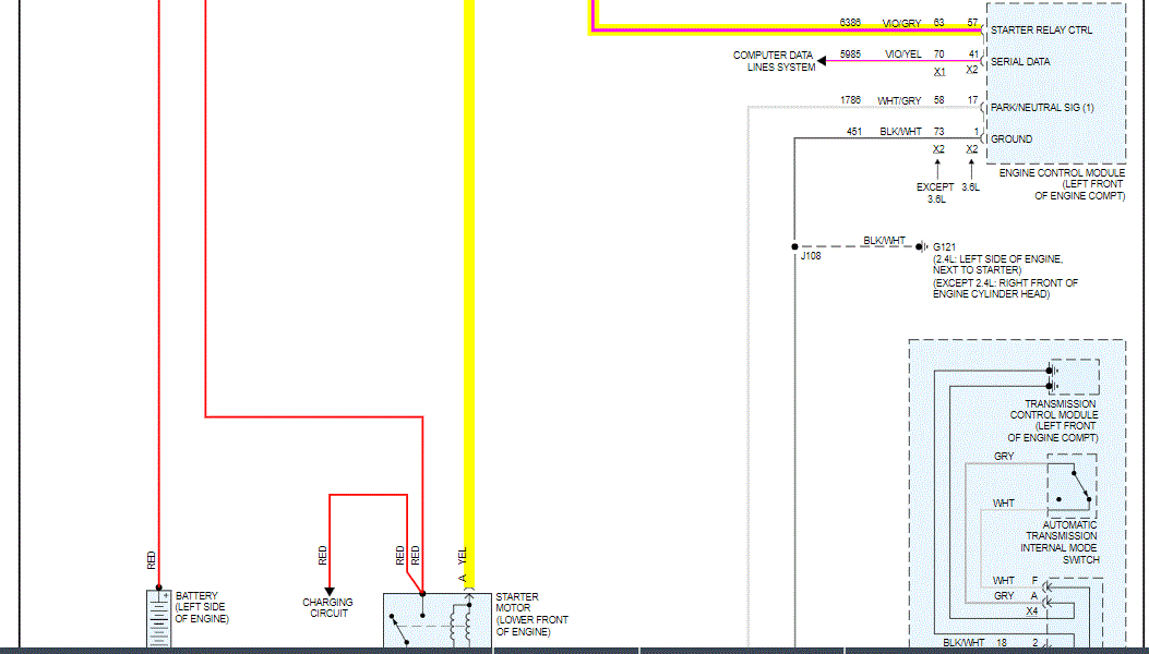
I attached a wiring diagram for you of the system.
https://www.2carpros.com/articles/how-to-check-wiring
Roy
Circuit/System Description
When the ignition switch is placed in the START position, a discrete signal is supplied to the body control module (BCM) notifying it that the ignition is in the START position. The BCM then sends a message to the engine control module (ECM) that crank has been requested. The ECM then verifies that the clutch pedal is depressed or the transmission is in Park/Neutral. If it is, the ECM then supplies 12 V to the control circuit of the starter relay. When this occurs, battery voltage is supplied through the switch of the starter relay to the starter solenoid.
Conditions for Running the DTC
The ignition is in the START position.
The system voltage is between 9.5-18 V.
Conditions for Setting the DTC
The ECM detects improper voltage on the control circuit of the starter relay.
Action Taken When the DTC Sets
DTC P0615, P0616, and P0617 are C type DTCs.
Conditions for Clearing the DTC
DTC P0615, P0616, and P0617 are C type DTCs.
Reference Information
Schematic Reference
Starting and Charging Schematics (See: Starting and Charging > Electrical)
Connector End View Reference
Component Connector End Views (See: Vehicle > Connector Views > Connector End Views By Name)
Description and Operation
Starting System Description and Operation (See: Starting System > Components)
Electrical Information Reference
Circuit Testing (See: Vehicle > Component Tests and General Diagnostics > Circuit Testing)
Connector Repairs (See: Vehicle > Component Tests and General Diagnostics > Connector Repairs)
Testing for Intermittent Conditions and Poor Connections (See: Vehicle > Component Tests and General Diagnostics > Testing for Intermittent Conditions and Poor Connections)
Wiring Repairs (See: Vehicle > Component Tests and General Diagnostics > Wiring Repairs)
DTC Type Reference
Power-train Diagnostic Trouble Code (DTC) Type Definitions (See: A L L Diagnostic Trouble Codes ( DTC ) > Diagnostic Trouble Code Descriptions > Power-train Diagnostic Trouble Code (DTC) Type Definitions)
Scan Tool Reference
Control Module References (See: Vehicle > Programming and Relearning) for scan tool information
Circuit/System Testing
1. Ignition OFF, disconnect the KR27 starter relay.
2. Ignition OFF and scan tool disconnected, open and close the driver door, and wait 1 minute. Test for less than 5.0 Ohms between the relay ground circuit terminal 86 and ground.
If greater than the specified range, test the ground circuit for an open/high resistance.
3. Verify a test lamp illuminates between the B+ circuit terminal 30 and ground.
If the test lamp does not illuminate, test the B+ circuit for a short to ground or an open/high resistance. If the circuit tests normal and the B+ circuit fuse is open, test the control circuit terminal 87 for a short to ground.
4. Ignition ON, verify that a test lamp does not illuminate between the control circuit terminal 87 and ground.
If the test lamp illuminates, test the control circuit for a short to voltage.
5. Parking brake applied and the transmission is in NEUTRAL or PARK. Momentarily install a 30 A fused jumper wire between the B+ circuit terminal 30 and the control circuit terminal 87. Verify the M64 starter motor is activated.
If the M64 motor does not activate, test the control circuit for an open/high resistance. If the circuit tests normal, test or replace the M64 starter motor.
6. Ignition OFF, connect a test lamp between the control circuit terminal 85 and the ground circuit terminal 86.
7. Transmission in park or neutral, command the starter relay ON and OFF with a scan tool. The test lamp should turn ON and OFF when changing between the commanded states.
If the test lamp is always ON, test the control circuit for short to voltage. If the circuit tests normal, replace the K20 ECM.
If the test lamp is always OFF, test the control circuit for a short to ground or an open/high resistance. If the circuit tests normal, replace the K20 ECM.
8. If all circuits tests normal, replace the KR27 starter relay.
Component Testing
Relay Test
1. Ignition OFF, disconnect the KR27 starter relay.
2. Test for 60-180 Ohms between terminals 85 and 86.
If not within the specified range, replace the relay.
3. Test for infinite resistance between the following terminals:
30 and 86
30 and 87
30 and 85
85 and 87
If not the specified value, replace the relay.
4. Install a 20 A fused jumper wire between relay terminal 85 and 12 V. Install a jumper wire between relay terminal 86 and ground. Test for less than 2 Ohms between terminals 30 and 87.
If greater than specified range, replace the relay.
Repair Instructions
Perform the Diagnostic Repair Verification (See: A L L Diagnostic Trouble Codes ( DTC ) > Verification Tests > Diagnostic Repair Verification) after completing the diagnostic procedure.
Relay Replacement (Attached to Wire Harness) (See: Power Distribution Relay > Removal and Replacement > Relay Replacement (Attached to Wire Harness))Relay Replacement (Within an Electrical Center) (See: Power Distribution Relay > Removal and Replacement > Relay Replacement (Within an Electrical Center))
Control Module References (See: Vehicle > Programming and Relearning) for ECM replacement, setup, and programming
Starter
Starter Replacement (V6)
Removal Procedure
1. Turn OFF the ignition.
2. Disconnect the battery negative cable. Refer to Battery Negative Cable Disconnection and Connection (See: Negative > Removal and Replacement > Battery Negative Cable Disconnection and Connection).
imageOpen In New TabZoom/Print
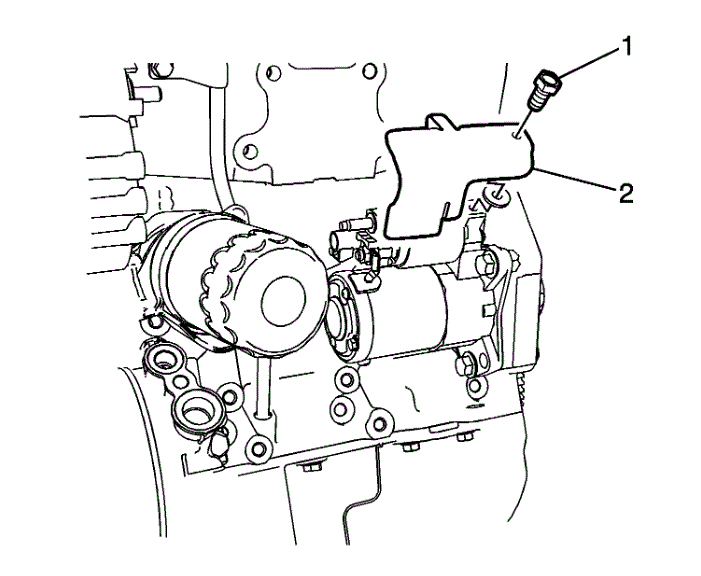
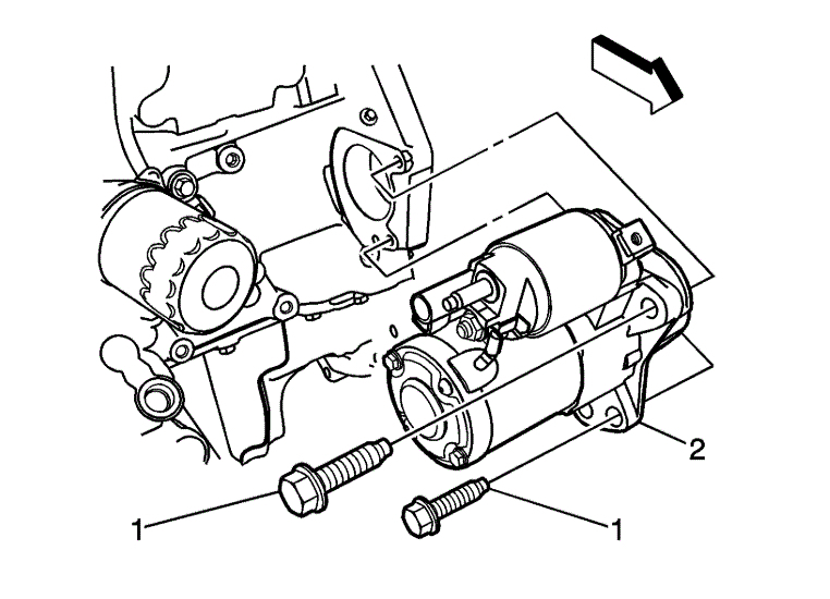
3. Remove the heat shield (2) from the starter.
4. Raise and support the vehicle.Refer to Lifting and Jacking the Vehicle (See: Vehicle Lifting > Procedures > Lifting and Jacking the Vehicle)
5. Disconnect the knock sensor connector.
imageOpen In New TabZoom/Print
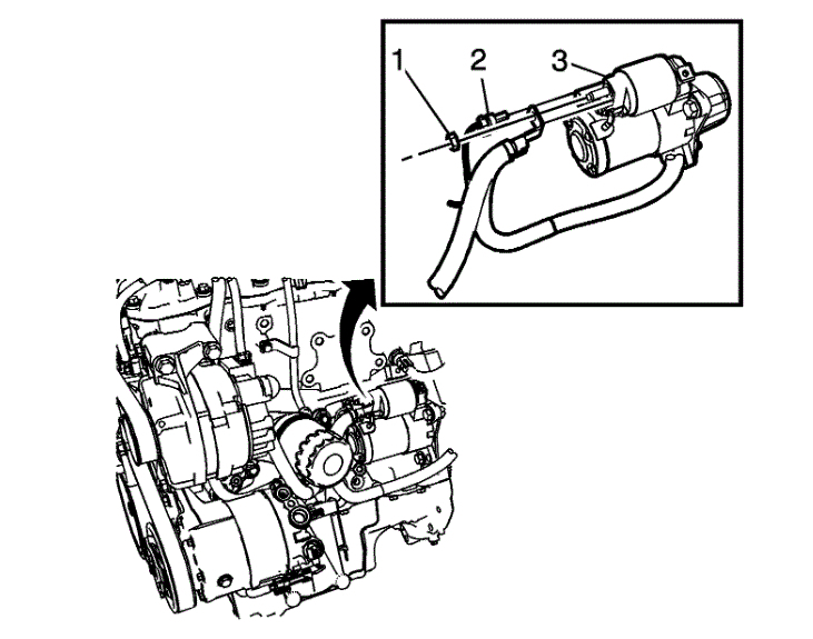
6. Remove the battery positive nut (1) and the engine harness connector (2), from the starter solenoid (3).
imageOpen In New TabZoom/Print
7. Remove the starter motor bolts (1).
8. Remove the starter motor (2).
Images (Click to enlarge)
Aug 5, 2020 at 9:10 AM