Dandy video, (thank you), but you inadvertently bypassed one key part of the test. That is to keep the test light's clip lead on the battery post, not on the engine or body. Regardless, the spinning starter would suggest the battery's ground cable to the engine is okay. I have to be careful when I say that because with no load on the starter motor, it's going to draw very little current, often less than 30 -50 amps. That's why bench-testing at an auto parts store often gives false or misleading results. Best is to test it under load, meaning spinning the engine. That's where it will draw between roughly 150 - 200 amps, and the cables have to be good enough to carry that much current.
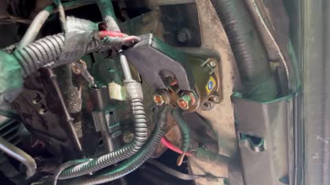
You followed the steps in the correct order at the relay, but Ford threw us a curveball. For decades they put the "starter solenoid" on the inner fender. It switches the 200+ amps for the starter, then an electromagnetic shoe on the starter motor moves the drive gear into mesh with the ring gear while the motor is already spinning. No other manufacturer, to my knowledge, ever did it this way.
Now Ford's starter circuit is the same as most other manufacturers use, with a "starter relay" on the inner fender. I suspect they did that to confuse us, but even though this is the same part as the older starter solenoid, and can be used in some of those applications, that's not what it is used for here. The story goes that when they stopped using them for the high-current solenoid function, they still had a golly-zillion of them in stock, so rather than buy a lot of inexpensive relays, they chose to use up their existing stock of these and call them the "relay".
In this application, they aren't passing the 200 amps to the starter. Every starter circuit can be broken down into three circuits; the low-current circuit, the medium-current circuit, and the high-current circuit. The low-current circuit includes the very tiny contacts in the ignition switch and neutral safety switch. That circuit passes about one amp to run the relay's coil. We know that's working because we can hear it clunk when it's engaged.
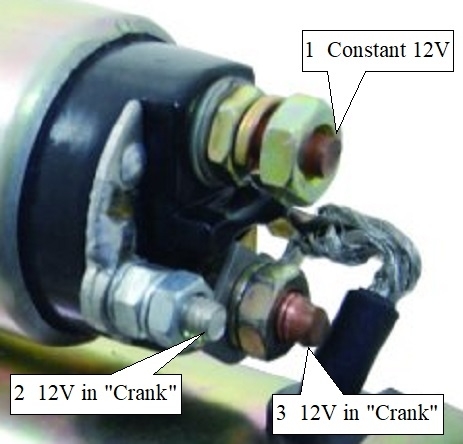
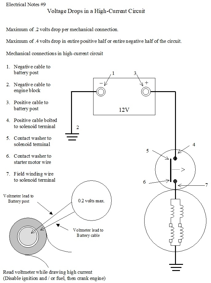
That relay switches on the medium current which now goes to the starter solenoid on top of the starter motor. Instead of over 200 amps, there will typically be less than 20 amps now. That shows up on the "Sol", (solenoid), terminal # 2 shown in this expanded photo. That causes the solenoid to activate. The first thing it does is a metal plunger moves a lever that slides the drive gear in to mesh with the ring gear. Just as it gets there, a large copper disc makes the connection between terminals 1 and 3. That turns on the high-current circuit and the motor spins.
What you did near the end of your video was to connect terminals 1 and 3 together. That made the motor spin, but terminal 2 didn't have 12 volts on it, so the plunger never moved the drive gear into position. The motor spun, but without spinning the engine.
Logic would tell us the battery cables are okay, but again, remember the motor was spinning with no ;load on it. A majority of one cable could be corroded away and the motor will still spin in this condition, but not when trying to spin the engine. For now we'll ignore that possibility and come back to it later if necessary.
What I'd like you to do instead is to crawl back under there with something that can handle 20 amps for a few seconds. Easiest is to use the blade of a screwdriver. We know there's 12 volts on terminal 1 from your last test. Connect terminals 1 and 2 together. There will be some small sparks, but nothing to get excited about. What should happen is the solenoid clunks into engagement, then the motor should run and crank the engine. One of three things is going to happen.
1. Nothing happens. No small sparks. No clunk.
2. A fairly loud clunk, but the motor doesn't run.
3. The motor cranks the engine normally.
1. If nothing happens, suspect a broken wire inside the solenoid. Further testing can confuse the issue even more because there's actually two coils of wire in there. Both are needed for the strength needed to shove the drive gear into engagement, then it is switched off to make its current available for cranking on a cold day. (That's called the "pull-in" winding). The second coil is called the "hold-in" coil because it is strong enough on its own to hold the spring-loaded plunger in place during cranking. If one of those coils has a break in it, the circuit will still test good thanks to the other coil, but one by itself is usually not strong enough to get the plunger to move. As a potential hint or clue, often that one coil can be made strong enough by connecting a larger battery charger. That raises the voltage and makes the one good coil stronger.
Another possible cause is the solenoid housing has warped causing the plunger to stick and not engage. You will still see the small sparks when you make the connection, but there will be no sound. This was real common on GM starters redesigned for the '87 model year. I haven't heard stories of this happening on other brands.
2. Probably the most common failure is the copper disc inside the solenoid, or its two contacts, have burned away. The plunger / drive gear will engage with a loud clunk, but the high current won't be switched on. You can test this yourself but it's rather cumbersome. It's easier with a helper running the ignition switch. Put the test light's probe on terminal # 3. The light will be off. Now energize the solenoid, either with the helper turning the ignition switch to "crank", or by you connecting terminals 1 and 2 together. The plunger should engage and the test light should turn on full brightness. If it doesn't light up during this test, but it does on terminal # 1, the copper disc is burned away or the plunger is sticking and not making it far enough.
If you do get 12 volts on terminal 3, either there's a worn brush in the starter motor or the negative battery cable is bad. Move the test light's probe to the starter motor's housing and redo the last test, but remember, the ground clip has to be on the battery's negative post. If the test light turns on, even dimly, replace the ground cable.
Starter motors are actually two motors built into one housing. Each one has a pair of brushes. It's somewhat common for a chip of carbon to prevent one brush from making good contact, but that ceases to be an issue the instant the other half of the assembly gets the armature turned just a little. It's when the brushes are worn down that at first, one of them makes intermittent contact. Everyone's familiar with people hitting the starter with a hammer or broom stick, then the starter works for a few days. It's likely due to worn brushes. That will only get worse over weeks or months. Once the first brush is badly worn, the starter will sound like the battery is bad. It will crank the engine too slowly, usually not fast enough for it to start. To add to the misery, a professional current draw test will show the starter is drawing close to what it is supposed to draw, not the half of normal that we might expect. That's a story for another day.
Let me know what you find with these last tests.
Jun 21, 2022 at 8:08 PM