Serpentine belt is loose

Tiny
TALLESTALPACA13
  • MEMBER
  • 2003 BUICK CENTURY
  • 3.1L
  • V6
  • 2WD
  • AUTOMATIC
  • 126,647 MILES
I'm having trouble figuring out where the tensioner is for my car listed above. My belt is severely loose and I can see the crankshaft spin but the belt doesn't move and it looks like there is no tension on the belt whatsoever, one edge of the belt looks like it's beginning to shred, too.

There's a diagram but I can't seem to figure out which cranks and pulleys are what. Any help and explanation would be appreciated.
Monday, February 15th, 2021 AT 1:40 PM

3 Replies

Tiny
ASEMASTER6371
  • MECHANIC
  • 52,797 POSTS
Good afternoon,

I attached the procedure and pictures for you below.

https://www.2carpros.com/articles/serpentine-belt-tensioner-replacement

https://www.2carpros.com/articles/replace-serpentine-belt

Roy

1. Remove the coolant recovery reservoir.
2. Remove the drive belt.
3. Remove the drive belt tensioner bolt.
4. Remove the drive belt tensioner.

1. Remove the drive belt tensioner by lifting or rotating the drive belt tensioner off of the drive belt, using a 3/8 inch breaker bar (1).

imageOpen In New TabZoom/Print

2. Remove the drive belt.

Installation Procedure

imageOpen In New TabZoom/Print

1. Install the drive belt.
2. Inspect the drive belt and the drive belt system.

imageOpen In New TabZoom/Print

Important: Make sure that the drive belt is aligned into the proper grooves of the accessory drive belt pulleys.

3. Install the drive belt under the drive belt tensioner pulley by lifting or rotating the drive belt tensioner, using a 3/8 inch breaker bar (1).

imageOpen In New TabZoom/Print

4. Ensure that the drive belt is properly routed.
5. Inspect the drive belt length scale on the drive belt tensioner for the proper installed length.

Was this
answer
helpful?
Yes
No
Monday, February 15th, 2021 AT 1:53 PM
Tiny
TALLESTALPACA13
  • MEMBER
  • 2 POSTS
Thank you so much for the quick reply! I located the belt tensioner, and then after further inspection, I realized that the belt is completely off of the Crankshaft/Harmonic Balancer. I attempted to try and slip it back on without having to loosen the tension, but unfortunately, that did not work. There is also a thin piece of rubber sticking out from the inner part of the Harmonic Balancer.
Was this
answer
helpful?
Yes
No
Monday, February 15th, 2021 AT 2:30 PM
Tiny
ASEMASTER6371
  • MECHANIC
  • 52,797 POSTS
You need to replace the balancer itself.

https://www.2carpros.com/articles/how-a-harmonic-balancer-works

You will need a puller to remove it and an installer tool to install it.

Roy

Tools Required
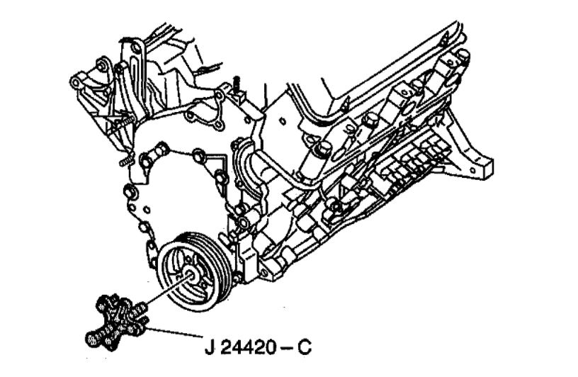
- J 24420-C Harmonic Balancer Puller
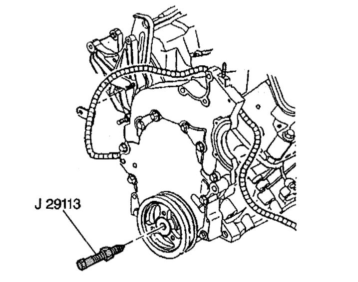
- J 29113 Crankshaft Balancer Installer
- J 36660-A Torque Angle Meter
- J 37096 Flywheel Holder

Removal Procedure

Notice: The inertial weight section of the crankshaft balancer is assembled to the hub with a rubber type material. The correct installation procedures (with the proper tool) must be followed or movement of the inertial weight section of the hub will destroy the tuning of the crankshaft balancer.

imageOpen In New TabZoom/Print

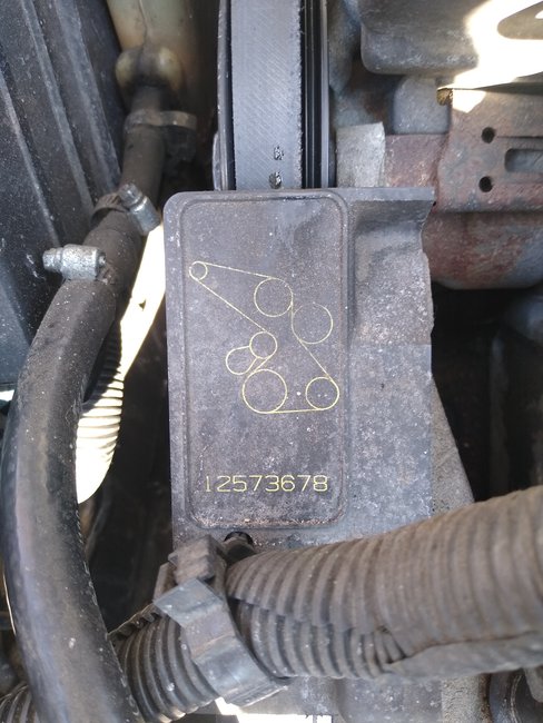
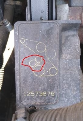
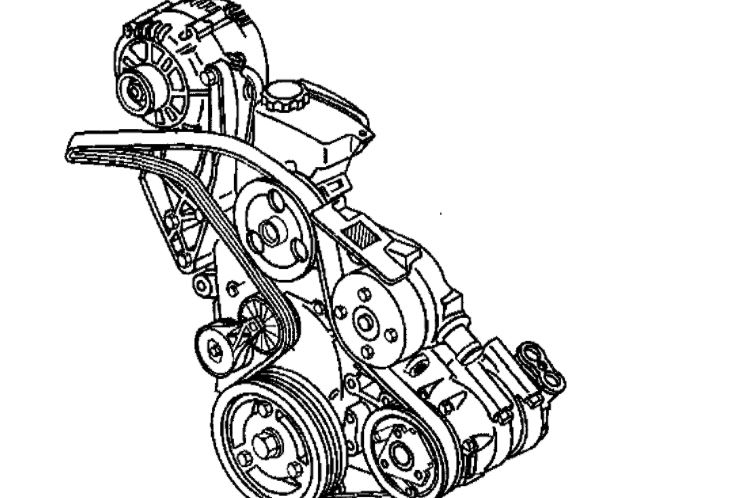
1. Remove the drive belt.
2. Raise and support the vehicle. Refer to Vehicle Lifting.
3. Remove the right front tire and wheel.
4. Remove the right engine splash shield.
5. Install the jack stands to the frame.
6. Loosen the left frame bolts and remove the right side frame bolts.
7. Using the jack stands, lower the right side of the frame to access the crankshaft balancer.
8. Remove the torque converter covers.
9. Install the J 37096 to the flywheel to prevent flywheel rotation.
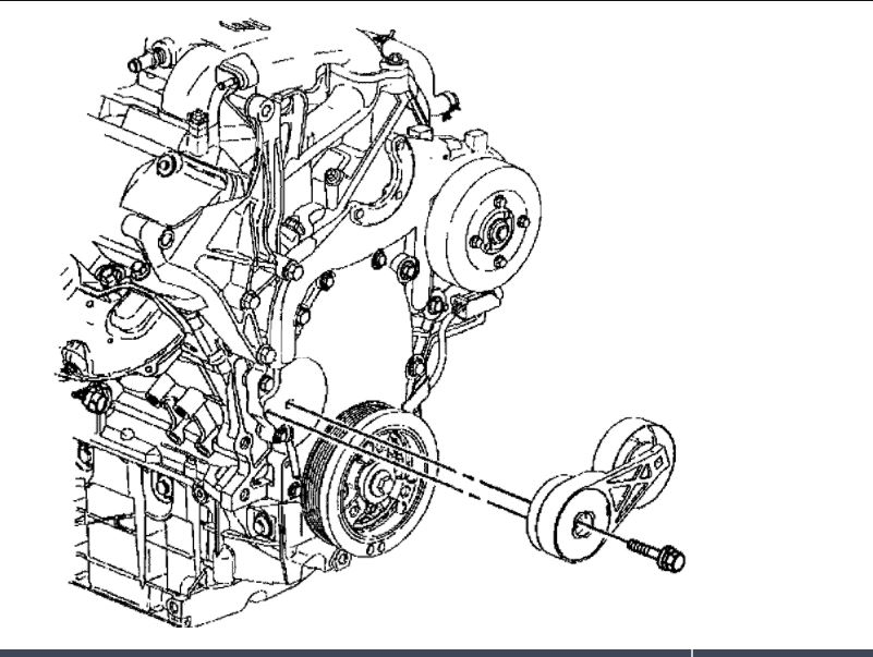
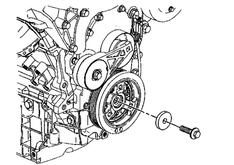
10. Remove the crankshaft balancer bolt and the washer.

imageOpen In New TabZoom/Print

11. Remove the crankshaft balancer. Use the J 24420-C.

Installation Procedure

imageOpen In New TabZoom/Print

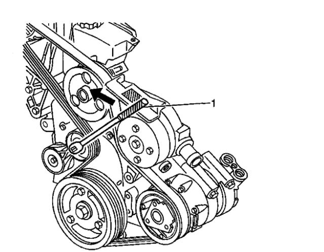
1. Apply sealant GM P/N 12346286 (Canadian P/N 10953472) or the equivalent to the keyway of the balancer.
2. Install the crankshaft balancer. Use the J 29113.
3. Remove the J 29113.
4. Install the J 37096 to the flywheel to prevent flywheel rotation.

imageOpen In New TabZoom/Print

Notice: Refer to Fastener Notice in Service Precautions.

5. Install the crankshaft balancer washer and the bolt.
5.1. Tighten the bolt to 70 Nm (52 ft. lbs.).
5.2. Use the J 36660-A to rotate the crankshaft balancer bolt an additional 72 degrees.
6. Remove the J 37096 from the flywheel.
7. Install the torque converter covers.
8. Raise the frame to the original position.
9. Install and tighten the frame bolts.
10. Install the right engine splash shield.
11. Install the right front tire and wheel.
12. Lower the vehicle.
13. Install the drive belt.
14. Perform a CKP system variation learn procedure.
Was this
answer
helpful?
Yes
No
Monday, February 15th, 2021 AT 3:14 PM

Please login or register to post a reply.

Sponsored links