Okay; here's what I worked on last night:
Part 2
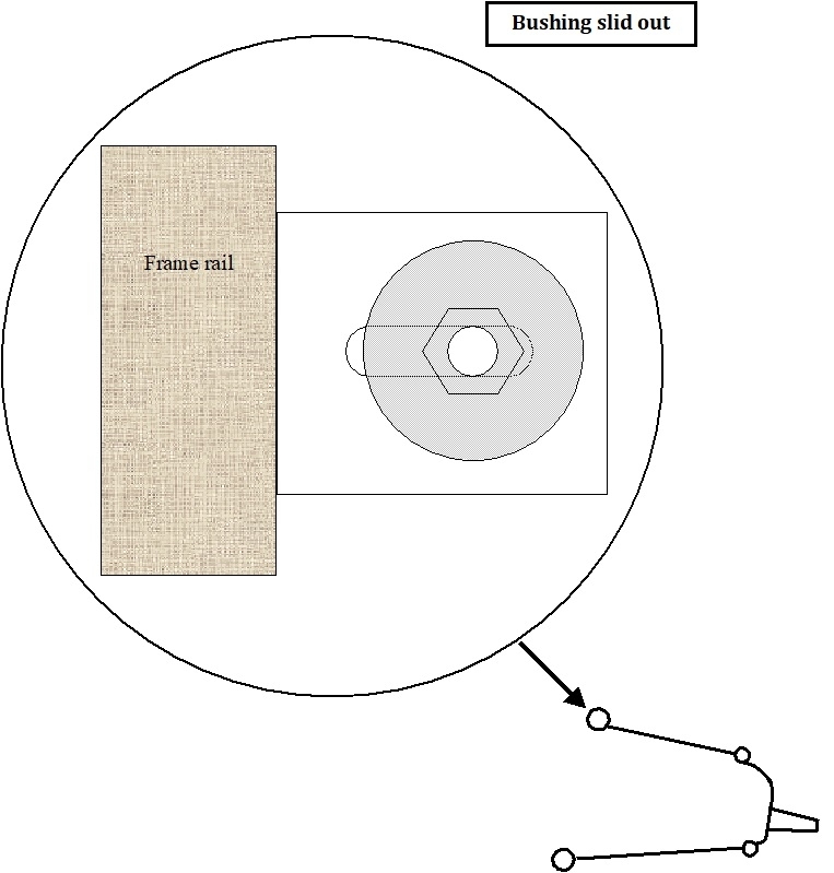
The fourth drawing is an expanded view of the upper control arm bushing that sits inside a metal bracket. Each side of that bracket has a slotted hole. The bolt goes through those holes and the hole through the center of the bushing. The bolt is shown slid out, away from the frame rail almost all the way.
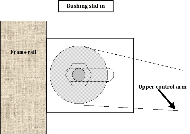
In the fifth drawing, the bolt and bushing are slid in, closer to the frame. That is how the control arm and upper ball joint are moved in and out to set camber, but it gets a little more complicated. Let me explain caster first.
A good way to see caster is to look at the front fork of a motorcycle or bicycle. It is angled rearward at the top. In this case the pivot points are centered right over the center of the tire. When you put weight on it, the tire wants to squirt out straight ahead. That is what allows you to ride no-handed.
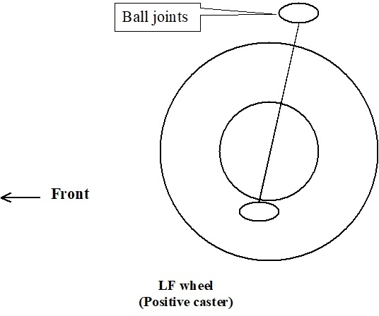
On your truck, the wheel is offset, or outside the pivot points, (ball joints). When you look from the side of the truck, as in the sixth drawing, the upper ball joint is further back than the lower ball joint. This is positive caster and matches the bicycle fork. As late as the mid '60s, most cars and trucks used negative caster. That made steering even a larger, heavy truck real easy without power steering. The tradeoff is negative caster is rather unstable and leads to steering wander and the need to constantly make corrections.
By the later '60s when we started driving faster and further, that wander got to be very tiring. Positive caster greatly increases directional stability, but it also increases steering effort, which would also be tiring. That's why power steering was added.
There's two alignment considerations with caster and camber. The first is tire wear. Camber is easy to see. If positive camber is too high, the wheel will be tipped out too far on top. The tire runs on the outer edge, so it wears down much faster than the rest of the tread. Caster is a little trickier. While the steering is set straight ahead, caster has no effect on tire wear, but for the benefit of others reading this, especially anyone preparing to take the suspension and alignment test for technician certification, caster is considered to be a tire wear angle. That's because when steering to one side, caster causes the wheels to tip in that direction. The further you turn the steering wheel, the more the wheels and tires lean, so the more weight is on the edges of the tires. That leaning mainly occurs at real low speeds, as when in a parking lot. Not many miles are put on that way, but for answering test questions, they still consider it a wear angle.
The other consideration is pulling, or drifting to one side when you let go of the steering wheel. Camber, again, is very basic. A tire wants to roll in the direction it's leaning. Besides setting both wheels to specs, we want camber to be as close to the same as possible. That way the left tire's pull will be offset by that of the right tire. When camber is not equal, the vehicle will pull toward the wheel with the higher camber setting. More on that in a minute.
Caster again has to be visualized. If it helps, exaggerate it for clarity. If you could imagine the upper ball joint moved back more and more until is straight behind the lower ball joint, it's easy to see if you put the truck's weight on it, that wheel would fold up with the tire hitting the frame. That's real extreme and would be considered 90 degrees. The ball joints straight over each other is 0 degrees. A common and typical spec for caster is around 3 degrees. Even with such a small value, if you placed the truck's weight on that tire, it would turn toward the center of the vehicle, and most of us wouldn't be strong enough to pull it back by hand. The other wheel does the same thing. It's when both spindles are connected with the steering linkage that the two forces offset each other. The higher the caster value, the harder that wheel wants to turn toward the center of the truck. If the left wheel is, . . . lets say 3 degrees, and the right one is 4 degrees, the right one will want to pull left harder than the left one wants to pull right. The right one will overcome the left tire's pull, plus have additional pull to the left. A one degree difference is significant and can be tiring.
Camber pulls very close to twice as hard as caster. To say that a different way, if you have a one degree caster pull to the right, and a half degree camber pull to the left, those pulls will exactly offset each other, and the vehicle will go straight. Those differences have to be factored in when we calculate the results in our head, but those must be kept as low as possible. When the differences get too large, while the pulls can still offset each other, it will cause instability, such as when the vehicle bounces up and down over railroad tracks. You'll see the steering wheel oscillate left and right as the front of the vehicle bounces up and down, while the truck keeps going straight.
Other things can affect how a vehicle pulls to one side, but we generally check the alignment first when diagnosing the cause. For smaller vehicles that use a front strut suspension system, they still have a lower ball joint, but the other steering pivot point is the strut's upper mount. Everything related to camber is the same, but not so with caster. I don't have a reason why, but while those vehicles do have specs for caster, a difference from side to side does not cause a pull on 99 percent of models. All alignment computers measure it automatically, but there is rarely a provision for adjusting it or is it necessary. I've had as much as a three degree difference, but no pull. With a three degree difference on your truck, you'd need both hands on the steering wheel to fight the pull.
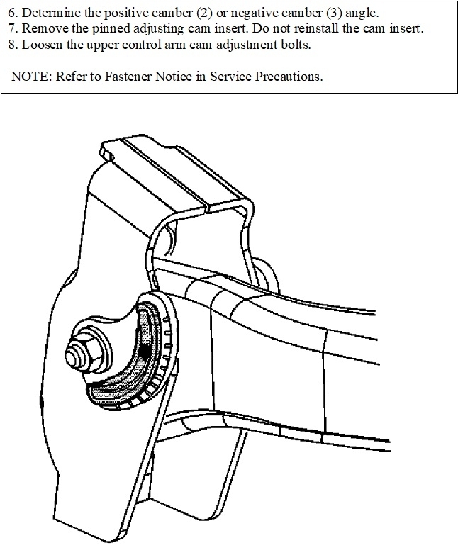
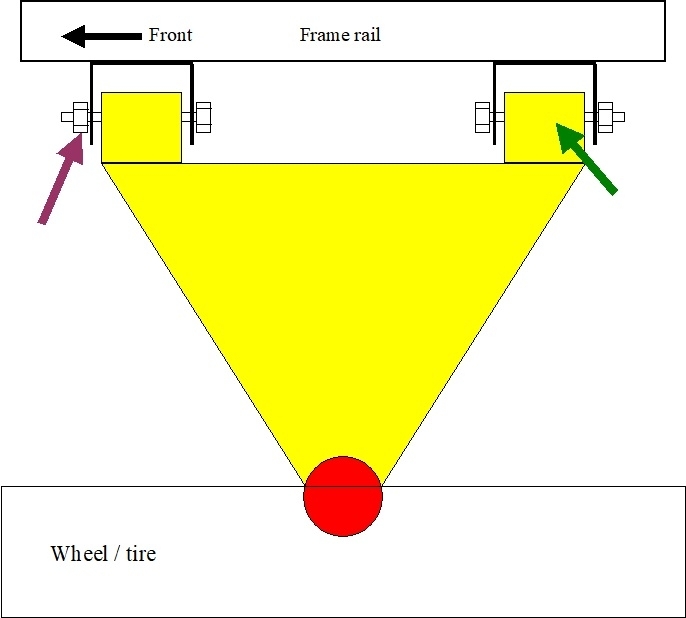
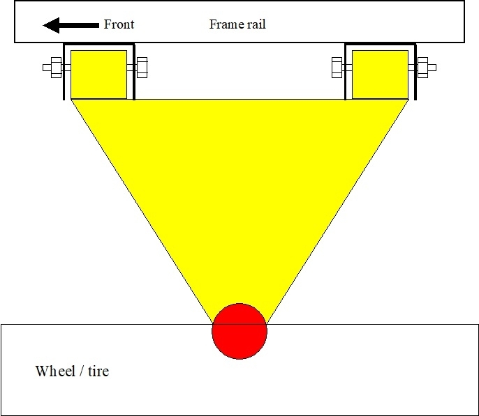
Okay, to finally address your original question, drawing 7 shows the upper control arm as viewed from looking down through the fender while standing next to the tire. This is the left front corner of the vehicle. The purple arrow is pointing to one of the bolts that must be loosened to allow that corner of the control arm to be slid in or out. The green arrow is pointing to the center of the bushing where, from your description, the bolt is rusted to the metal sleeve in the bushing. Most of the time once the nut is loosened, hammering on the end of the bolt lets it release enough to allow adjustment. The bolt doesn't have to be free to rotate.
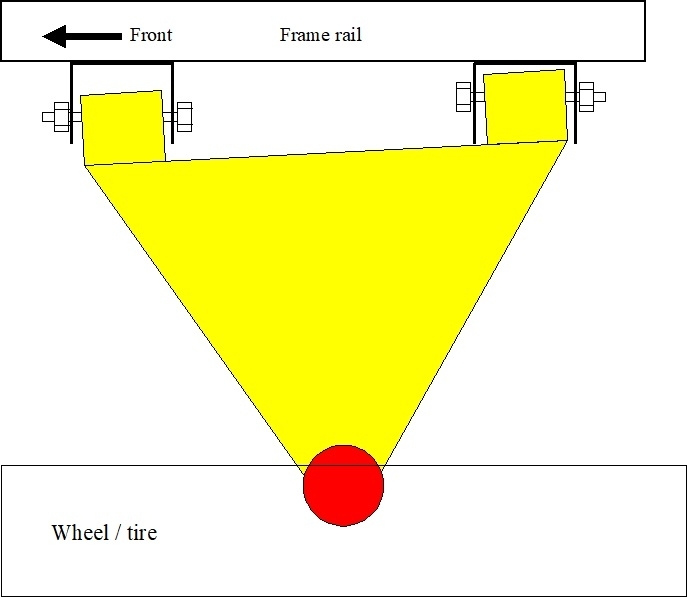
Both corners of the control arm are slid out all the way. That wheel will have too much positive camber. Compare that to the arm in the eighth drawing. Here both corners are slid in all the way. Now that wheel will have too much negative camber. Both of these corners need to be adjusted somewhere in the middle of that range. Adjusting both equally in or out changes camber.
Where the fun, (frustration) starts is in the ninth drawing. If the front bushing is pulled out, and the rear bushing is pushed in an equal amount, camber will stay the same, but the upper ball joint will move rearward. That increases positive caster. One bushing in and the other one out changes caster. Both in or both out changes camber. The goal now is to jockey them around until you get both camber and caster where you want them. We have to be very picky with camber due to its huge effect on tire wear. We can take whatever we get with caster, within reason. Way more important than the tiny amount of tire wear, caster is responsible for the steering system self-returning to center after you make a turn. Also, the higher the caster, the harder it is to turn the steering wheel, but the faster it returns to center.
Where the bigger problem occurs is when we move on to the second wheel. We have to set camber to specs, and match it to the first wheel, but now we can't just take whatever caster ends up at. We have to get caster to match the first wheel while also still matching camber. Very often we run back and forth changing first one wheel, then the other one, until we get the readings close enough. Starting in the '60s, Chrysler used these same two bolts, but they had offset "cam" bolts. Those have a built-in washer offset from the threaded section. Those did have to be free to rotate. As you turn the bolt head, the bolt was forced to slide in or out. That made making tiny, accurate adjustments real easy with the added benefit those bolts couldn't slip accidentally if you hit a curb. They still use a similar cam bolt on their struts, making camber adjustment real easy. With your design, the bolts have to be tightened very securely to prevent that accidental slipping. Those two benefits is why your truck had those plastic cams under the bolt heads, but those were only for use on the assembly line.
If you get a printout of the alignment, I can interpret the numbers for you. Back when all we had was large, heavy rear-wheel-drive cars, it was sufficient to measure caster and camber to the nearest eighth or sixteenth of a degree. Alignment equipment was mechanical. Once light-weight front-wheel-drive cars showed up, especially those with strut suspension, we needed a real lot more precision. At a minimum, we can set our alignment computers to read to a tenth of a degree. That is only done by mechanics who are more interested in time over customer satisfaction. At the dealership I always set my computer to read to the hundredth of a degree. That brings me to my last point of value. We always adjust in a slight left-hand pull to offset the results of "road crown". That's the slant to the right so water runs off the road surface. With your truck and older similar cars, we could do that with about a quarter degree more camber on the left wheel or a half degree more caster on the right wheel. Back in the '90s, with little cars with struts, I had the best luck when adjusting in 0.06 degrees more camber on the left side. There's no way you could get that precise with old mechanical equipment. That's also why I set my computer to read to that much accuracy. That's for people who are more interested in no customer complaints even though it takes a lot more time to get good results.
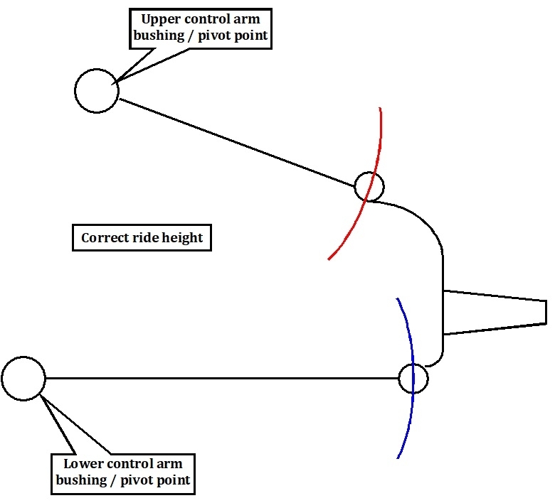
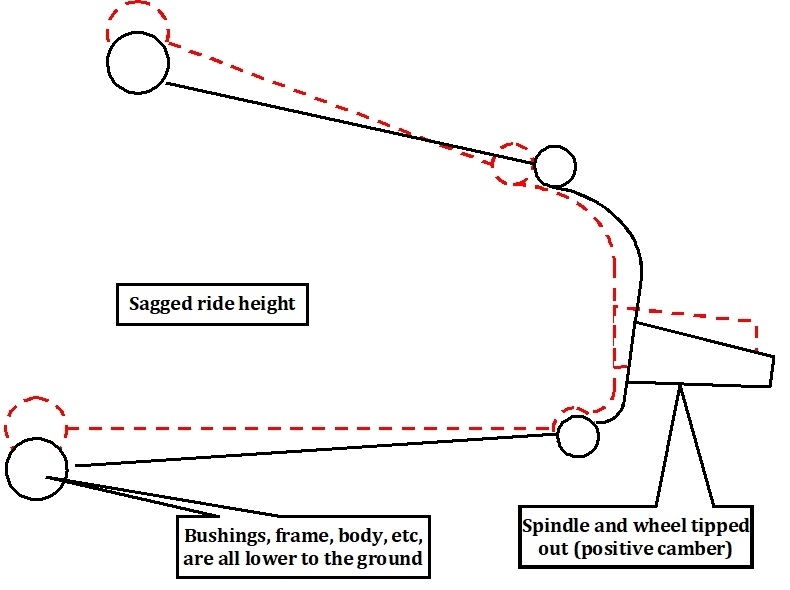
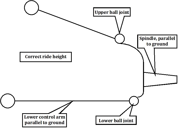
I know that's a lot to take in, but now I want to apply that to ride height. The frame rail, upper and lower control arms, and the spindle form four sides of a geometric relationship resembling a square. When at the correct ride height, as the spindle moves up and down, it tips in and out on top just enough to reduce one cause of tire wear. When the spring sags, that geometric relationship is all messed up. It results in the tire tipping in and out an exaggerated amount, and the tread slides back and forth sideways across the road surface more than normal. That is why all the alignment numbers can look perfect, but you'll still have horrible tire wear.
Another way to look at this is if you start with both wheels in perfect alignment, then do nothing except lower the ride height, camber readings will have gone out of specs. If all you do is readjust camber, as many inexperienced mechanics do, the numbers on the computer will again look perfect, but you'll still have real bad tire wear due to the geometric angles being wrong. Numbers on the computer only apply to a vehicle that is standing still. Tire wear comes from the changes in those angles as the car is bouncing up and down. This is where if you do not readjust any alignment angles, but just raise ride height back up to where it should be, it beings all the alignment angles back to where they used to be, which was correct.
One more clue to be aware of, when you said you had miserable tire wear, but there was no mention of pulling or crooked steering wheel, that immediately suggests to me nothing got hit, bent, or shifted, so the alignment adjustments aren't the cause of that wear. It's ride height that is the much better suspect, and you can correct or improve that yourself. The exception is if someone previously readjusted caster and camber while the ride height was sagged and not corrected first. Now, once ride height is brought back to specs, camber will change and no longer be in specs. It will have to be readjusted after ride height is corrected.
"Toe" is the last of the three main alignment angles. That's a story for another day. Tire wear can be summed up in camber wear is always a factor on that one tire, although it can be out of adjustment on both wheels. If camber is only wrong on the left wheel, you'll have excessive edge wear on just that one tire. Toe wear always affects both tires equally, even when just one is misadjusted. Toe is the direction the tires are steering when turned straight ahead. If both wheels are out of adjustment equally, you can still have a straight steering wheel, but real bad tire wear. If only one wheel is misadjusted, the steering wheel will be off-center, along with tire wear on both tires.
I'd be happy to type up a lot more on toe, but I'll need another night or two.
Images (Click to enlarge)
Nov 24, 2022 at 6:27 PM