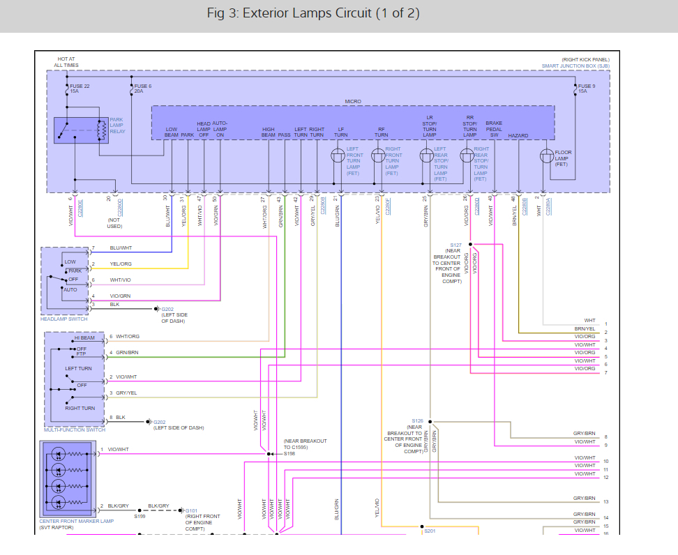
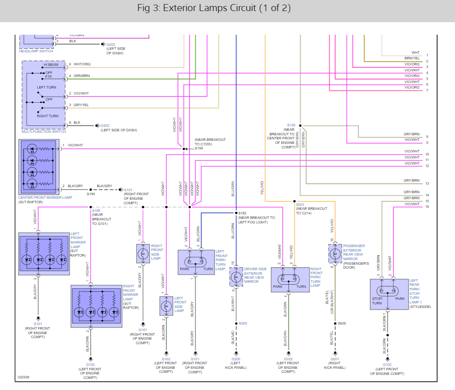
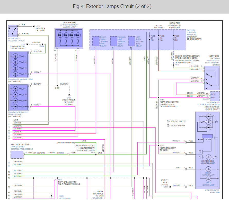
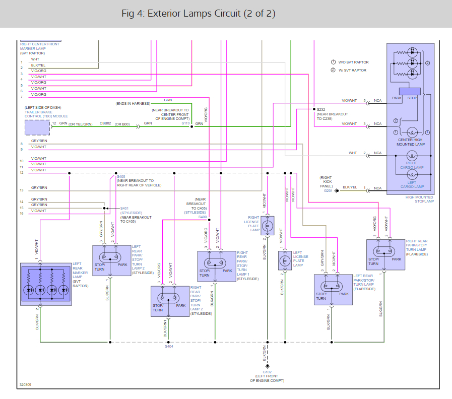
So, this system is controlled by a smart junction box which is located at the right kick panel. If all of the fuses are good this box needs to be replaced here are the blinker wiring diagrams so you can see how the system works and I have included how to change the unit out to fix the problem, check out the images below.
Removal
NOTICE: Electronic modules are sensitive to static electrical charges. If exposed to these charges, damage to the module may result.
NOTE: Prior to the replacement of the module, it is necessary to upload the module configuration information to a scan tool. This information must be downloaded into the new Smart Junction Box (SJB) after installation. For additional information, refer to Section 418-01 to carry out Programmable Module Installation (PMI) .
NOTE: For the SJB to accept the PMI procedure, the following conditions must be met:
The headlamp switch must be in the OFF position (must not be in the AUTOLAMP position, if equipped)
The key must be in the ON position
The driver door must be open
The doors must be unlocked electronically by pressing the door lock control switch to the UNLOCK position momentarily
Failure to follow this procedure results in the PMI procedure failing.
NOTE: The Tire Pressure Monitoring System (TPMS) functionality is integral to the SJB .
NOTE: A new SJB is delivered in a "manufacturing mode" with 8 pre-set DTCs. A successful configuration of the SJB , then a successful TPMS sensor training, and a successful self-test including the clearing of all DTCs is required in order to clear the 8 pre-set manufacturing mode DTCs. The 8 manufacturing mode DTCs are:
B106D (Tire Pressure Monitor System [ TPMS ] Initiators Not Configured) — This DTC is present when the SJB is not configured, even on applications that are not equipped with initiators.
B2477 (Module Configuration Failure)
B2868 (Left Front Tire Pressure Sensor Fault)
B2869 (Right Front Tire Pressure Sensor Fault)
B2870 (Right Rear Tire Pressure Sensor Fault)
B2871 (Left Rear Tire Pressure Sensor Fault)
B2A21 (One or More Configuration Files Missing or Corrupt)
C2780 ( ECU in Manufacturer Sub-State)
NOTE: This step is only necessary if the SJB is being replaced.
Upload the module configuration information from the SJB into the scan tool. For additional information, refer to Section 418-01 .
Turn the key to the OFF position.
Remove the RH cowl panel side trim.
Disconnect the electrical connectors.
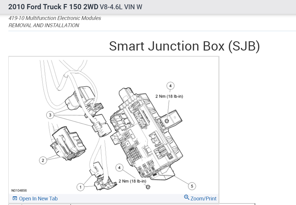
Remove the 2 bolts and the SJB .
Installation
Position the SJB and install the 2 bolts.
Tighten the bolts to 2 Nm (18 lb-in).
Connect the SJB electrical connectors.
NOTE: If the SJB is not being replaced, this is the last step that is necessary.
Install the RH cowl panel side trim.
NOTE: DTC B2276 may be set, indicating there are less than 2 transmitters programmed to the SJB . For additional information, refer to Section 501-14 .
Download the SJB configuration information from the scan tool to the SJB . For additional information, refer to Section 418-01 .
Train the tire pressure sensors. For additional information, refer to Section 204-04 .
NOTE: The SJB DTC C2780 does not clear if any other DTCs are still present in the SJB .
NOTE: This step is required to clear the SJB DTC C2780, allow the SJB to exit the manufacturing mode, and to make sure there are no other concerns with the newly programmed SJB .
Carry out the SJB self-test (must include an on-demand self-test) and then repeat the self-test to confirm all SJB DTCs have been cleared.
Rotate the instrument panel dimmer switch from the full dim position to the dome ON position. This makes sure that all displays are visible under all lighting conditions.
Check out the images (below). Please let us know what happens.
Images (Click to enlarge)
Dec 11, 2022 at 12:23 PM