Radiator fan motor not working?

Tiny
SOPHIE BRUNO
  • MEMBER
  • 2010 SUZUKI GRAND VITARA
  • 2.2L
  • 4 CYL
  • 4WD
  • AUTOMATIC
  • 85,000 MILES
Hello gentlemen,
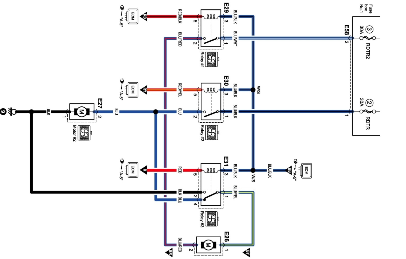
Motor is not working
Wired direct battery to fan motor connectors heard a sound like a shirt or a capacitor discharging repeated it three times sound gone motor dead.

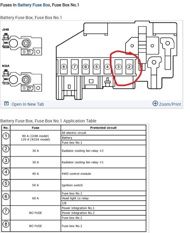
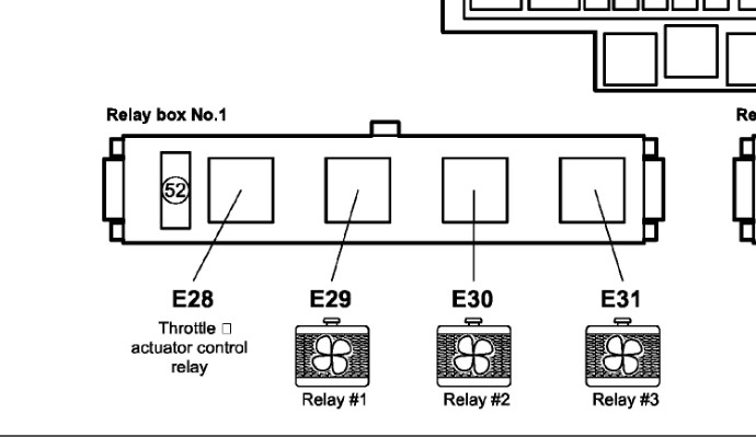
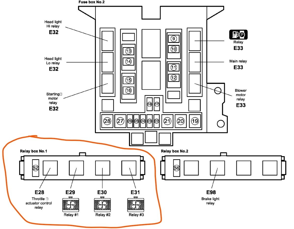
Checked fuse and fan relay power on all the time the control side was on all the time both terminals this baffled me.

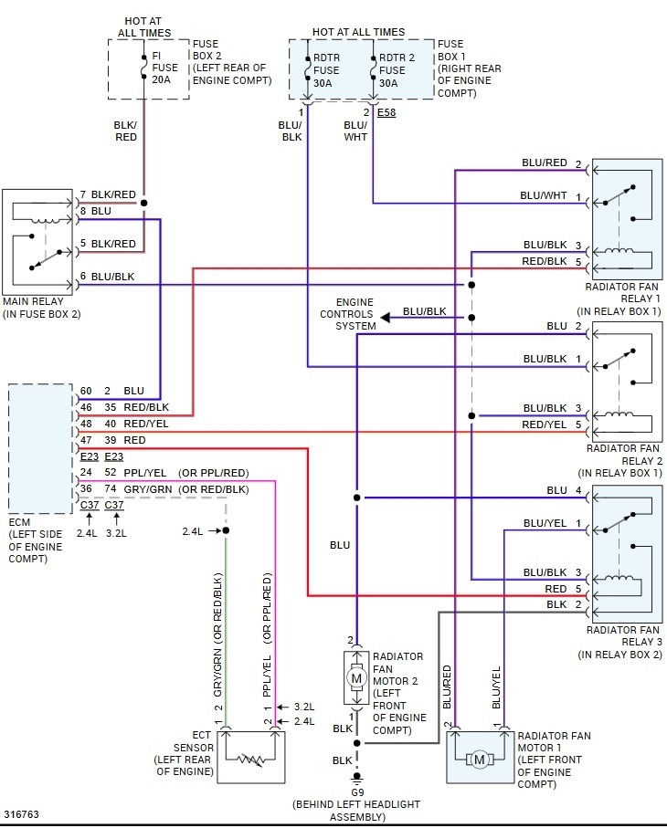
The engine coolant temperature sensor disconnect, grounded my test light to battery neg, placing the top into the connector yet nal motor did not spin.

Could it be a harness short.

The fan motor blades are not frozen they are free moving.

Could it be a reset leaning issue the battery was disconnected while installing a new fan unit.

Respectfully,
Sophie Bruno
Wednesday, July 2nd, 2025 AT 3:31 PM

22 Replies

Tiny
STEVE W.
  • MECHANIC
  • 14,726 POSTS
Okay, so you tried going directly to the battery with the fan wiring and it made a strange sound but didn't turn. Sounds like the motor failed internally. Sounds like you know the testing process. This is the wiring for that if it's a US vehicle.
Was this
answer
helpful?
Yes
No
+1
Thursday, July 3rd, 2025 AT 2:13 AM
Tiny
SOPHIE BRUNO
  • MEMBER
  • 23 POSTS
Thank you, I could not check the fuse box under the dash no, no description. I used a short detector on radiator harness the needle wiggles and points down in direction of short it pointed up right without wiggling when it led to the motor of radiator fan. I hope your wire diagram includes the dash fuse box. How do I fix fan motor or can I buy it individual motor on Amazon.
Respectfully,
Sophie Bruno.
Was this
answer
helpful?
Yes
No
Thursday, July 3rd, 2025 AT 4:11 AM
Tiny
STEVE W.
  • MECHANIC
  • 14,726 POSTS
HMM, the image didn't make it through. There are 2 fuses in the fuse box at the battery. They protect the relays and the fan motors. Then there are the relays that control the fan motors. This system works by using the three relays together to regulate the fan speeds. In the "low" speed the relays run the power in a loop through both fans so that they are in series and run on about half the battery voltage. Then if the engine keeps getting warm the ECM triggers the third relay to toggle it and now both fans are getting the full battery voltage. They work by changing the ground path through the motors. So, in "low" the power comes from both fuses to the relays, however relay 1 is the only relay that turns on. That sends power from the relay through the Blue red wire to motor #1, then it comes out of the motor on the Blue yellow wire to relay 3 which is "off" and it passes the power through into the Blue wire that goes to fan motor #2 and finds the ground through that motor on the Black wire. In that mode having a bad relay or motor in either location would stop the fans from turning. Now the engine starts to get hot and needs more cooling, the ECM now turns on all 3 relays. That now sends the power from relay 1 to fan 1 as normal, but with relay #3 now on the power is sent directly to the black wire and ground. That gives fan on1 full battery voltage, and it turns faster. Also now, because relay #2 is now on it sends power through the blue wire directly to fan motor #2 and it now gets full battery voltage and runs at high speed. A quick test that generally works is to unplug the engine coolant temp sensor. This tricks the ECM, so it turns on both fans on high to protect the engine from overheating.
Or you can pull the relays and test the circuits by jumping relay terminals. If you use a test light to check the fuses and have power on both, then you pull the relays out of the relay box. You should find power on relays 1 and 2 at the #1 terminal in the socket. If the key is on you should also find power fed to the relays from the main relay on terminal #3 of each socket. That is the power for the relay coil. The ECM then supplies a ground through the individual red wires to turn the relays on as needed. So, you should find power on terminal 3 in all three relay sockets. And power on terminal 1 in sockets 1 and 2. To test the wiring the easy way, take a jumper wire connected to battery positive and use it in the relay sockets. When you touch it to terminal 2 in relay two, one of the fan motors should come on. That would show that the power circuit from that relay is good, and the ground for both fans is good (they share the ground circuit). Now to test the other circuit put a relay back into socket #3 and apply power to terminal 2 in relay socket #1. If the wiring and fan motor is good, you should now see both fans on but at a lower speed as they make the low-speed circuit. If they don't turn it on, then it's likely a bad motor. For replacement you would need to replace the cooling fan motor(s). As the dealer network no longer exists you might find the parts online. There are two different motors. As you look at the fan assembly there are a left and a right motor. The left motor is part #1712065J10 and the right motor is part #1712065J00.

(Your short finder will point at the fan motors because they are essentially a piece of wire wrapped around the core and then going to a ground point, so they look like a shorted wire).
Was this
answer
helpful?
Yes
No
+1
Thursday, July 3rd, 2025 AT 9:15 AM
Tiny
SOPHIE BRUNO
  • MEMBER
  • 23 POSTS
Reply followed all instructions, check all the fuses first in bay box all good and the 40 and 30 amp fuses the bigger ones all good.
Key off rely to two had bat power all the time except for relay 1 and 3.
Key on relay 1 and 3 had no battery power it had even control side power.

I jumped relay 2 bat power to slot 2 the ground side motor did not spin.

Key I jumped relay 1 control side power to ground no response.

Key on jumped relay 3 control side power to ground. Jumped to bat ground as well no response car is cold.

Turned the car on after ten minutes repeated the jumper to grounds on all 3 relays no response. No response then removed the engine coolant sensor no response to motors they are dead motored.

Now I will search on Amazon for the motors thank you for the part. Looking on Amazon so far, I have not yet found them. I will try eBay. Auto zone has the whole shroud with motors for 500.00 dollars I cannot afford it. Thank you, Steve for your expertise help. I understood why relay 2 has two control side power.
Respectfully,
Sophie
Was this
answer
helpful?
Yes
No
Sunday, July 6th, 2025 AT 10:23 AM
Tiny
STEVE W.
  • MECHANIC
  • 14,726 POSTS
Just to be sure. With the key on you should have power to pins 3&1 on relay 1 (control and main fuse) On relay 2 you should also have power on pins 3&1 (control and fused) then on relay 3 you would have power only on pin 3 (control only) If those are what you found then the power side is good. Fan 1 should power on if you apply positive power to terminal 2 in relay 1 socket and ground to terminal 1 in relay 3 socket. Then fan 2 should come on if you apply power to terminal2 in socket 2 or terminal 4 in socket 3. Just want to verify that.
If neither motor powers up Verify the ground to the motors. Wouldn't want you to spend money only to discover the ground was bad. Another thing, connect up a test light in place of each fan and see if they come on while testing. If they work but no fan then you have bad motors. Parts wise look on RockAuto. Com They show 5 brands from 120-250 dollars for complete assemblies. SKP SK621509, DORMAN 621509, CONTINENTAL FA72653, UAC FA50510C and TECHPRO SZ3115107. I'd probably opt for the UAC, I've used that brand before.
Was this
answer
helpful?
Yes
No
+1
Sunday, July 6th, 2025 AT 3:59 PM
Tiny
SOPHIE BRUNO
  • MEMBER
  • 23 POSTS
Wow ok, Steve specific trouble shootings.

Slots and pin terminals, of relays I need a confirmation on how to locate them exactly.
What I do could be wrong, I count the relay slots from left to right rows one and rows two from passenger side to drivers side. Is it wrong is the right way and x cris cross pattern.

Now the relays 1, 2, 3. I found relay 2 is between relay s 1 and 3. Is this correct. The fuse box says fan 1 is relay 3. So relay 1 is to the left diagram labels it fp and 3rd relay I can't remember I deduce it's rely 3.

I used om meter on big fuse the three 49 amp 40 amp and 55 amp the fuse read a resistance dropping to 0L what does it mean?

From memory, key off, relay 2 had bat power and two control side powers all the time from ecm.

Key on. Bat power was found on rely 1 and rely 3 on different slot terminals is this ecm control power side, I cannot differentiate this.

I count terminal slots from left to right in rows of two. Is this wrong, is it from cris cross x pattern.

If I place test light on bat positive on relay 1 and 3 and place it's too in the unit terminals and not really know that with key on that power is control power I think it bat power and really mess up things and make a 5000 dollar mistake scares me. I could blow computers transistors assuming it is control side power is really bat battery power and confused about which terminal slots is ground wirer to the motor.

I will follow your instructions step by step I checked all the fuses in engine bay I found no blown fuses.

Respectfully
Sophie
Was this
answer
helpful?
Yes
No
Monday, July 7th, 2025 AT 1:47 PM
Tiny
STEVE W.
  • MECHANIC
  • 14,726 POSTS
The relay block you want should have 4 relays in it in a line. The relay with the fuse next to it you disregard. Then the relays should be labelled in the sockets they plug into as E29 E30 and E31 They are the relays and should be 29= 1, 30= 2, 31= 3. The relays themselves will look like the picture and have 4 or 5 terminals with internal wiring as shown. For the relay internal wiring diagram the ABCDE translate to the external terminals as - A and B would be 3 and 5. C will be 1, D will be 2 and E will be 4. Now one thing to remember is that the coil can be connected either way, that is because you are viewing the relay upside down, so in the socket with 5 terminals there will be 3 one direction and 2 at a right angle. The three will be A - E4 - B the two terminals at 90 degrees will be D2 - C1 (C on the end), A can be either 3 or 5 depending on which one they wired as power and B is the same.
Did that help at all. It's one of those things that I can look at and understand but describing it is different because there are about 4 different ways that they describe the terminals.
For instance some relays will be labelled as the coil as 85 and 86, then the terminals as 87 and 30 with 87A as the normally closed. The last image is looking into the relay socket.
Was this
answer
helpful?
Yes
No
+1
Monday, July 7th, 2025 AT 7:02 PM
Tiny
SOPHIE BRUNO
  • MEMBER
  • 23 POSTS
Thank doctor. Oops my medic back ground. Steve you are a doctor and the big difference is you do not kill humans is that a wonder. Thank you Steve I will report back after checking the ground wire to the relay slot terminals. Dis connecting the motors.
Respectfully
Sophie Bruno.
Was this
answer
helpful?
Yes
No
Wednesday, July 9th, 2025 AT 11:08 AM
Tiny
STEVE W.
  • MECHANIC
  • 14,726 POSTS
Funny you mention that, Not a doctor but do have 25 years as a FF/EMT myself. Rode the bus for many years.
Was this
answer
helpful?
Yes
No
Wednesday, July 9th, 2025 AT 4:12 PM
Tiny
SOPHIE BRUNO
  • MEMBER
  • 23 POSTS
That's amazing synchronicity I spoke from heart. Thank you. I will report back to you on ground wirer.
Respectfully
Sophie.
Was this
answer
helpful?
Yes
No
Thursday, July 10th, 2025 AT 9:22 AM
Tiny
STEVE W.
  • MECHANIC
  • 14,726 POSTS
We will be here. No rush.
Was this
answer
helpful?
Yes
No
+1
Thursday, July 10th, 2025 AT 10:15 AM
Tiny
SOPHIE BRUNO
  • MEMBER
  • 23 POSTS
Hello Dr Steve.
Update on the ground wire testing.
I used two test lights one to bat power other to ground.

Key on found all the bat power terminals and control power terminals.

I found the bat grounds and the control side grounds place test light to bat power on all grounds they lit up bright ground wires are good.

I disconnected radiator connector s, one test light connect to relay grounds from bat positive other test light on ground wire it lit up from disconnected radiator connectors.

I had taken off relays first to find the ground terminals on all 3 relays then plug them half way and heard the sound of a dead motor. Vlunck.

Use an volta meter to oms to see resistance on motor wire it was high and quickly drop to OL. What does ol mean and why did resistance drop to zero?

Relays out I jumped the ground terminals to battery power after reconnecting radiator no motor response.

What is did not do was to back probe the radiator connector and the temperature sensor did connected. I did do it earlier I had reported with engine running and temperature sensor disconnected waited 29 minutes fan motors did not turn on.

I get confused because I don't understand the principals of integrated cir units I know the computer is alive and sending a 5 volt reference when backed probed.

I think I may need to buy a new shared with two motors. What do you think Mr Steve.
Respectfully
Sophie Bruno.
Was this
answer
helpful?
Yes
No
Monday, July 14th, 2025 AT 11:56 AM
Tiny
STEVE W.
  • MECHANIC
  • 14,726 POSTS
It sounds like you have a couple of bad motors. One item to try, Connect a test light in place of each fan ( they run in series in low and parallel in high, if you don't have a good circuit in both motors it stops both of them from working. You don't have access to a bi-directional scan tool do you? With that you could likely turn the fans on and off easily. However I'm not sure which ones would cover that vehicle very well, even though they show coverage.
Was this
answer
helpful?
Yes
No
+1
Monday, July 14th, 2025 AT 5:52 PM
Tiny
SOPHIE BRUNO
  • MEMBER
  • 23 POSTS
Hello Dr Steve W,
I don't have the scanners of quality it very expensive yet very efficient.

The parallel circuit runs two separate ground from an unknown junction I cannot see and the serial circuits runs both motors from a junction
tracing a shared ground for higher speed and the serial for lower speed shares the common ground from computer to temperature sensor down through relays to the motors it's my impression that the ground wires current are flowing but I don't have a amp current wire tester and would I have to open the harness to isolate a yellow red wire to test current flow or can I test current flow from the relay fan relay 2 is the second relay between relay 2 and 3. It has a constant battery power with key off and constant control side power from ECM with key off. The other relays do not show constant power with key off only when I turn key on the 1 and 3 relay show battery and control power, With key on.

I still have to re read your example using test lights did not fully visualize yet on my mind. Thsnk you sir Steve W for your patient and intergrativr scientific mind in helping me survive the tyranny of car manufacturers and presidents who is king and empower and a want to be god. I am terrorized from all sides. 3carpros technicas are life savers for the working class I fear I will lose my card the Toyota Corolla 2000 and the 15 year old grandvitsra, 2010 I cannot afford the insurance next year. Grateful to you men who save families.
Respectfully
Sophie Bruno.
Was this
answer
helpful?
Yes
No
Monday, July 14th, 2025 AT 7:56 PM
Tiny
SOPHIE BRUNO
  • MEMBER
  • 23 POSTS
Hello Steve W,
Thank you for the wire diagram I have glanced the wire diagram, I have seen throttle sensors, the camshaft the and crank sensor fuel pump sensors all share the common grounds allowing all comments to active current flow to start car like magic I mean technology magic.

I did not check relays health by work testing them properly. I will do this and report back to you. It is safe to logically assume this results work they start up the car fine and fuel injector respond to relays.

My next move is to remove radiator fan shroud and open motors to see if magnets are broken, to see if anatuer rotating filaments are rusted inhibiting electron flow sand paper might clean off the rust,

If I cannot fix the motors I will have to save to afford the prices. Thank you for recommending auto parts outlets I will be checking them out. Mr Steve W and the state of California thank you for your intergratetive and differential diagnosis you have helped and giving me courage because you illustrated the depths of knowledge it motivated me towards facing this challenge.
Respectfully,
Sophie Bruno.
Was this
answer
helpful?
Yes
No
Wednesday, July 16th, 2025 AT 7:05 AM
Tiny
SOPHIE BRUNO
  • MEMBER
  • 23 POSTS
I forgot to tell you I backed probed the temperature sensor the ground signal wirer reads 3v reference from ECM computer is responding.

I remember telling you that when one unplugs a defective senor the grounds flow and the computer remembers the sensors the radiator motors would have started, it did not. I am certain that Steve you isolated the problem I with your help covered the absolutes and the variables.
Respectfully,
Sophie
Was this
answer
helpful?
Yes
No
Wednesday, July 16th, 2025 AT 7:13 AM
Tiny
STEVE W.
  • MECHANIC
  • 14,726 POSTS
The grounds on the fans are somewhat deceptive because of the way the system operates. There are the two motors in the fan shroud. In low speed operation the power goes into one motors positive lead, then out of the negative lead and into the second motors positive lead. Then through that motor to ground. That way you end up with effectively one half of the battery voltage going through each motor. So they spin slower. Then when the temperature calls for higher fan speed the relays engage and it now treats them as two individual motors by splitting the ground. Now instead of two motors in series each one is fed full battery voltage and you het high speed operation.
The catch to this system is that a failure of the ground or either motor leaves you with no fan operation. You said you tried connecting them directly back in your post and that the fan made strange noises but didn't work. To me that sounds like at least one of them failed. That alone would stop them from operating on low speed.
The idea with the two test lights is that they would go in place of the fan motors and would light up during testing. So the light(s) come on = fans would get power and turn on. That would show that the control circuits are operating and that the fans are the problem. I've used headlight bulbs as test lights in those cases because they are a larger load, many don't have them just laying around though. So just a common test light will work.
Was this
answer
helpful?
Yes
No
+1
Wednesday, July 16th, 2025 AT 9:13 AM
Tiny
SOPHIE BRUNO
  • MEMBER
  • 23 POSTS
Hello Steve,
Now I am remembering my mistakes after reading your explanation it clear on my mind now.

I had used two test lights one to bat positive the other to bat neg, my mistake was I had disconnected both fan motors not understanding the series circuit, I had disconnected both fans wire connectors testing them separately each time I heard the sound coming from the fan motors.

I will disconnect fan on driver side fan 1 leave fan two connected use clips wire clamp to secure test light tip. Motor electrons travel to second fan in series st lie power. It's a great test Steve.

What I did not tell was iam just remembering after reading your description, I had disconnected both fans testing individually, the idea came into mind to use a jumper on fan terminal to the other fan terminal it did not matter which is positive or negative the polarity is either left or right but my jumper eure was a thick gauge I could not stabilize the wire so I held it while holding the test light tip hooked up to battery power I heard the sound again I was more confused then when I started. The second test is to turn car on with test lights clipped to the first fan connector wait for temperature sensor to signal the ECM to active high power in parallel circuit.

I will report to you in two days thank you Steve.
Respectfully,
Sophie
Was this
answer
helpful?
Yes
No
Wednesday, July 16th, 2025 AT 12:19 PM
Tiny
STEVE W.
  • MECHANIC
  • 14,726 POSTS
No rush. Take your time. We will be here.
Was this
answer
helpful?
Yes
No
Friday, July 18th, 2025 AT 7:43 AM
Tiny
SOPHIE BRUNO
  • MEMBER
  • 23 POSTS
Hello Steve,
I performed the test with two fan motors.

I used a volt meter to find the serial fan power with the key on.

Disconnect one fan motor at a time leaving one fan connector in connection mode.

First fan connector tested show no power on the connector harness side.

The second connector showed ground terminals power 0.01. And power terminal showed 0.10 power on harness side with key on and first fan motor reconnected, key is on.

One test light on battery power and other test light to bat neg, with two clip wires, both test light's are now connected to fan motor, with key off. Following the polarity of these two fans in series.

Everything is isolated and in position the motors did not spin.

Next with the key on the motors did not spin and the test lights did not light up.

Next engine is running warming up after 10 minutes the fan propellers did not spin afterwards I tapped the fan motors on each side to shake off rust from brushes they did not spin either.

After 30 min turned engine off.
I removed temperature coolant sensor, use volt meter to test for for a ground power it registered 0.O5.

Next left the sensor unplugged and turned key engine started. Waited 20 to 15 minutes the temperature gauge inside dash board on the Middle. I oversexed for 10 minutes more no fans motors did not engaged. The key off, connecting the harness side to temperature sensor, started engine waited another 10 minutes to if the ECM and temp sensor would turn the fans motors, no response

I kept telling the fan motors while engine running no response.

It's Saturday I was planning to remove the fan shroud, I now decided to wait for your insight Mr Steve, your input is valuable I will wait till Tuesday next week.

Respectfully,
Sophie Bruno.
Was this
answer
helpful?
Yes
No
Saturday, July 19th, 2025 AT 10:44 AM

Please login or register to post a reply.