Power running board installation?

Tiny
LINO GALMOT
  • MEMBER
  • 2013 FORD F-150
  • 90,000 MILES
Hi, I have the truck listed above and I want to install a power running board. I removed it from another truck and want to install it in mine. I'd be interested in getting the wiring diagram so I can try to install it, since it's a Ford original. I don't know if you can get it for me.
Monday, March 31st, 2025 AT 3:49 PM

33 Replies

Tiny
STEVE W.
  • MECHANIC
  • 14,516 POSTS
Attached are the wiring for the module that controls the boards and how they are mounted. You will need the control module (9L3Z-14C177-B) that mounts to the rear wall of the cab and the harness that connects it to the rest of the truck. On some the harness is there but it depends on the option package. You also need the switch panel that allows manual operation. Once installed you need a scan tool to go in and activate the option code to make them operate.
I think FORScan has the ability to activate them, but you would need to ask them specifically. They cannot be set up to simply extend and retract with a switch because the motors use signal feedback on the CAN network for the module and switch to work.
Was this
answer
helpful?
Yes
No
Monday, March 31st, 2025 AT 5:48 PM
Tiny
LINO GALMOT
  • MEMBER
  • 22 POSTS
Thanks for responding. I appreciate it. That's the module I have. I only have the power and ground wires located, obviously the ones that connect to the motors, but I can't find where the others connect.
Was this
answer
helpful?
Yes
No
Monday, March 31st, 2025 AT 7:18 PM
Tiny
LINO GALMOT
  • MEMBER
  • 22 POSTS
This is the module I have.
Was this
answer
helpful?
Yes
No
Monday, March 31st, 2025 AT 7:23 PM
Tiny
STEVE W.
  • MECHANIC
  • 14,516 POSTS
Yes, that is the control module. The wiring for the truck to the module is the Blue with red wire to battery positive, Black with yellow is the ground, then the two CAN lines that go to the network are on pins 7 and 8. The other 8 wires go to the boards and their sensors as the second diagram shows. It looks like you have the major components, you don't have the dash switch though. That allows you to select deploy - retract - or automatic. That connects to the CAN bus and signals the BCM and board module. Not something that you can control with a toggle switch though.
Was this
answer
helpful?
Yes
No
Monday, March 31st, 2025 AT 8:22 PM
Tiny
LINO GALMOT
  • MEMBER
  • 22 POSTS
Do you mean this one?
Was this
answer
helpful?
Yes
No
Monday, March 31st, 2025 AT 8:47 PM
Tiny
LINO GALMOT
  • MEMBER
  • 22 POSTS
The communications network module is this? Apology.
Was this
answer
helpful?
Yes
No
Monday, March 31st, 2025 AT 9:02 PM
Tiny
STEVE W.
  • MECHANIC
  • 14,516 POSTS
No the network is already in the truck you want to install them on. The module connects to that network. That connector may already be in place. It would be on the back wall of the cab behind the trim panel, under the rear window.
Was this
answer
helpful?
Yes
No
Tuesday, April 1st, 2025 AT 1:05 AM
Tiny
LINO GALMOT
  • MEMBER
  • 22 POSTS
Could you send me an image so I can identify the communications network module? I looked for it in the area you indicated, at the rear of the cabin, below the window. I only found the rear power window motor and connector, but nothing else.
Was this
answer
helpful?
Yes
No
Tuesday, April 1st, 2025 AT 10:39 AM
Tiny
LINO GALMOT
  • MEMBER
  • 22 POSTS
2013 ford f150pls
Was this
answer
helpful?
Yes
No
Tuesday, April 1st, 2025 AT 10:40 AM
Tiny
LINO GALMOT
  • MEMBER
  • 22 POSTS
Hello.
Was this
answer
helpful?
Yes
No
Tuesday, April 1st, 2025 AT 2:27 PM
Tiny
STEVE W.
  • MECHANIC
  • 14,516 POSTS
Those two wires go to the medium speed CAN network that connects many of the modules in the truck. Those are the highlighted wires in the first diagram. The box that you have with the connectors mounts to the rear wall of the cab. If it has the connectors there already then great, however I believe they are only installed when the truck is ordered with those boards as an option. As such you need to sort out the wires to each board first. Then you have a power and ground and the two wires you question which connect to the network using a plug that should be in place behind the trim panel where the module mounts under the rear window in the area that the window motor connector is. The third image shows where the module you have should mount and where the connectors would be if your truck has them. If you don't find them then you will need to make a harness for the three pieces you have.
Was this
answer
helpful?
Yes
No
Tuesday, April 1st, 2025 AT 10:10 PM
Tiny
LINO GALMOT
  • MEMBER
  • 22 POSTS
Hi Steve, good morning. Yes, my truck doesn't have the connectors for the power running board module. It only has the connector for the rear window motor and the heated windows. So, I'll have to troubleshoot them or make the connections, which I think will be difficult since I don't have much experience reading the diagrams you sent me. By the way, thank you very much. I'll try it out and let you know how it goes. Thanks so much for your time.
Was this
answer
helpful?
Yes
No
Wednesday, April 2nd, 2025 AT 11:16 AM
Tiny
STEVE W.
  • MECHANIC
  • 14,516 POSTS
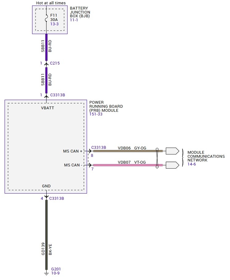
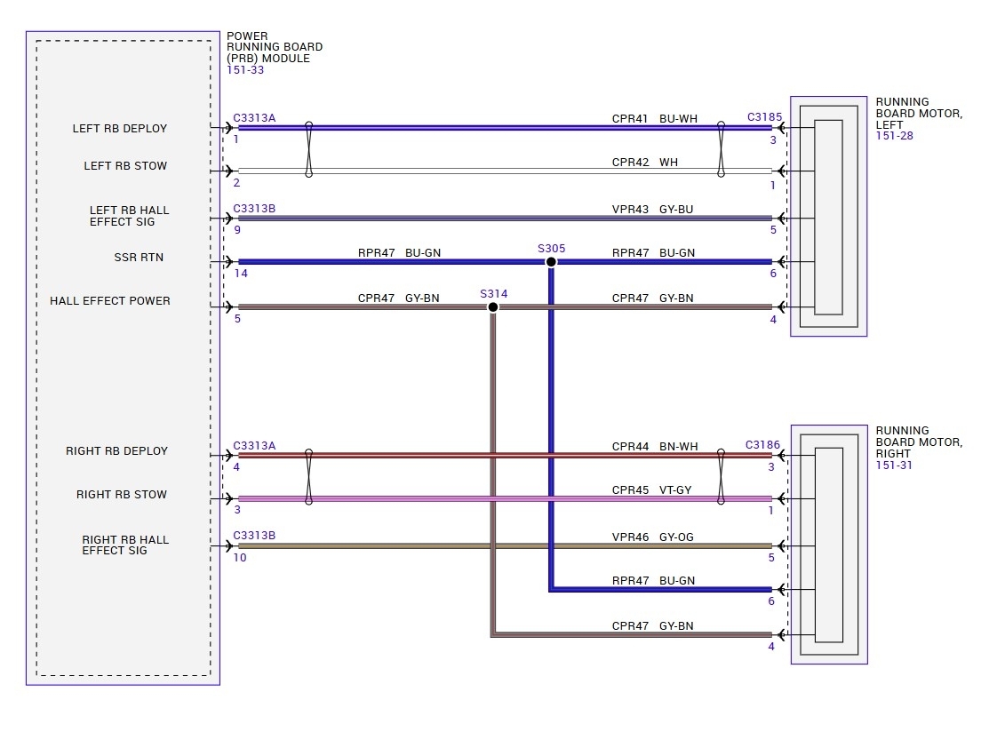
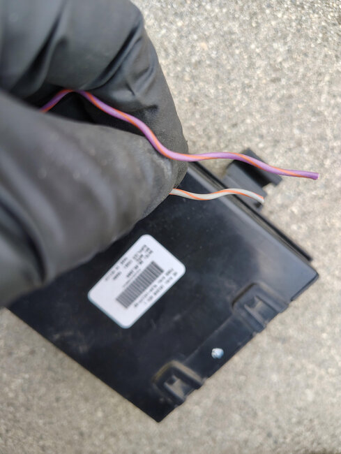
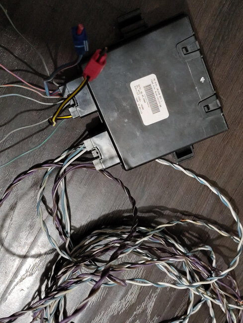
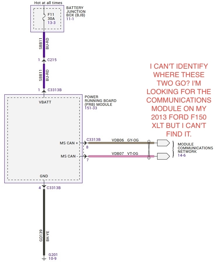
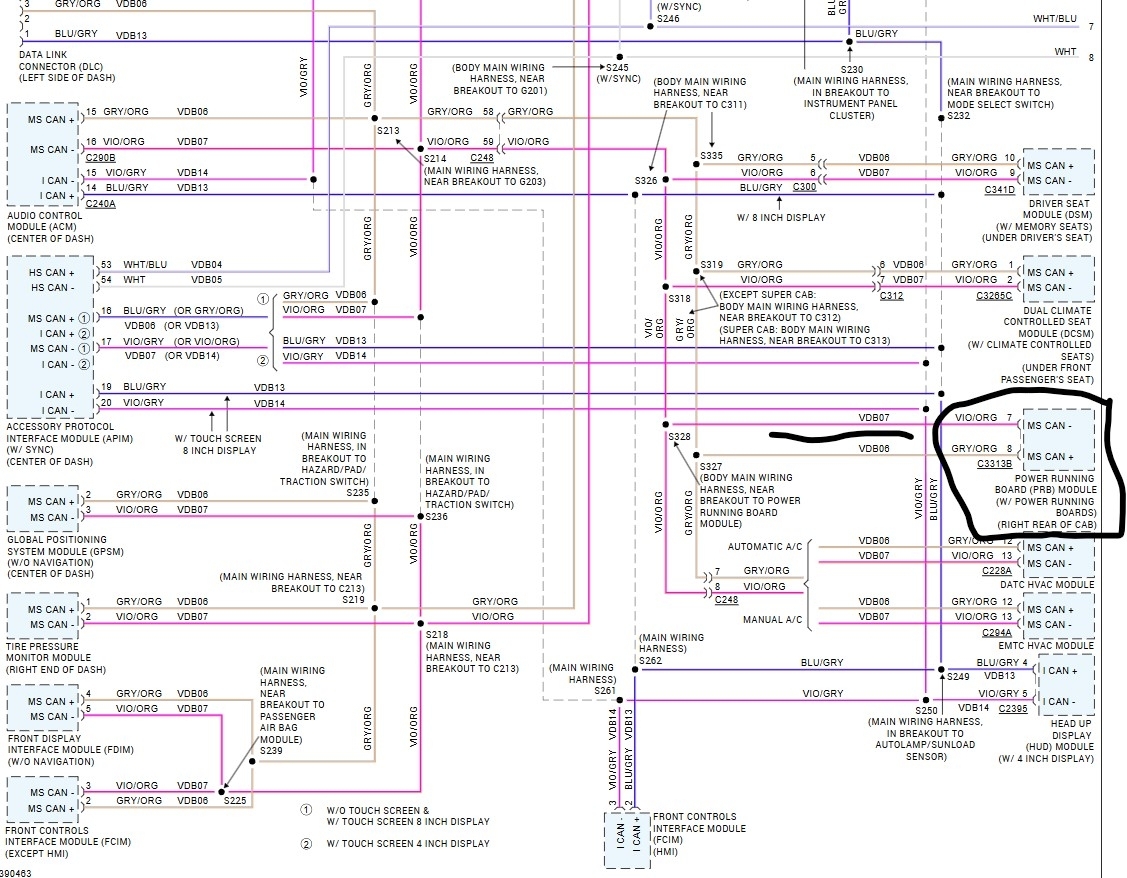
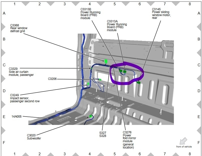
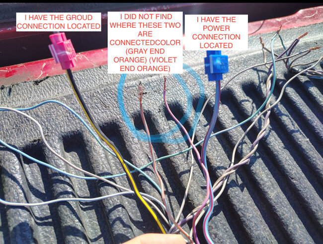
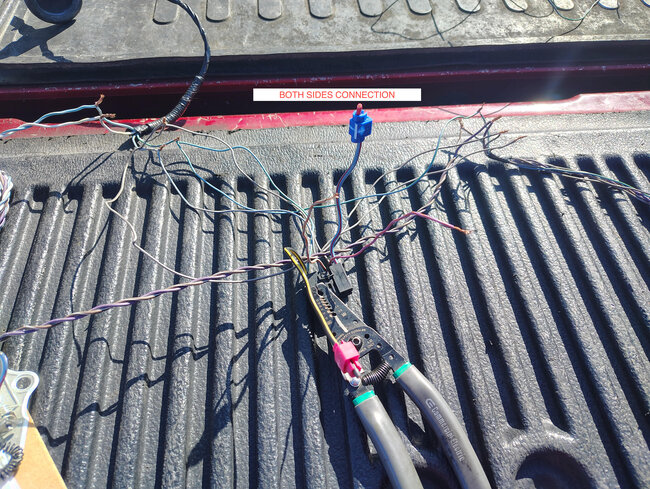
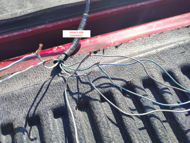
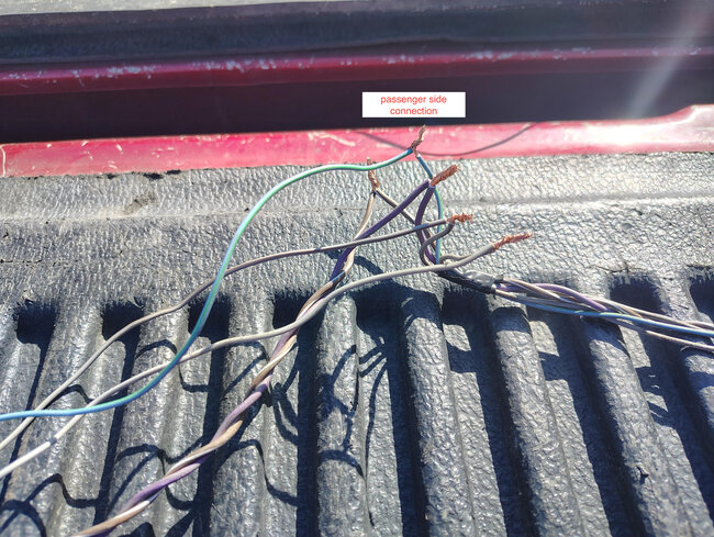
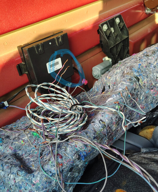
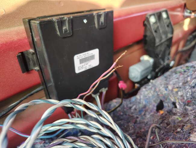
Yeah it looks like they didn't put them on the trucks that didn't have the option package. That means you will need to make the harness. It isn't really that difficult. You just match up the colors between the two sides to the connectors you already have. So, for the left sideboard (drivers' side) you need the blue and white twisted pair plus a gray w blue, a blue w green and a gray w brown wire. So, 5 wires that should go to the connector that you have with the large boot on it, one of them likely already has those colors in it. The right side would be the brown with white and violet with gray then a gray with orange and the same blue with green and gray with brown wires that you used on the other side. It looks like there are stubs for all of those in the connectors you have for the module. Then there are 4 wires that connect to the truck side, those are the gray with orange and violet with orange that will connect to the network and the power (Blue w red) and ground (black with yellow)
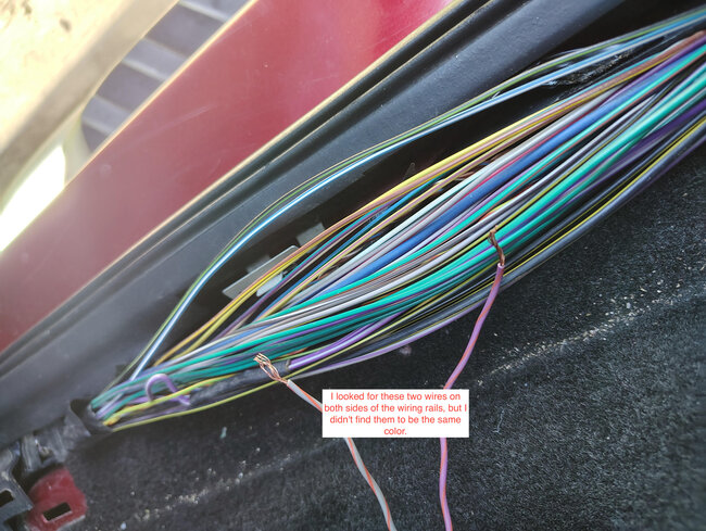
Now if you look Ford was nice and used mostly different colors except they re-used the gray with orange. However, they are on two different pins in the connectors, and they go to different locations.
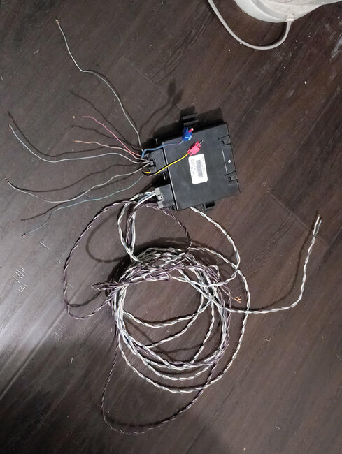
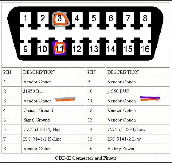
So, you would end up with one harness with 5 wires that would go from the module out to the driver's side, another with 5 wires to the passenger side and the last with 4 wires that would end up going up to the front of the truck. And could actually be tied into the truck near the OBD connector to make it easier.
Was this
answer
helpful?
Yes
No
Wednesday, April 2nd, 2025 AT 11:53 AM
Tiny
LINO GALMOT
  • MEMBER
  • 22 POSTS
I made these simulating connections but I still have the same problem. I can't find where the two already marked cables are going to be connected.
Was this
answer
helpful?
Yes
No
Wednesday, April 2nd, 2025 AT 5:53 PM
Tiny
LINO GALMOT
  • MEMBER
  • 22 POSTS
Both connections.
Was this
answer
helpful?
Yes
No
Wednesday, April 2nd, 2025 AT 5:55 PM
Tiny
LINO GALMOT
  • MEMBER
  • 22 POSTS
QA
Was this
answer
helpful?
Yes
No
Wednesday, April 2nd, 2025 AT 6:22 PM
Tiny
STEVE W.
  • MECHANIC
  • 14,516 POSTS
They connect to the trucks data lines. You won't find them out in the open because they only run to the modules that use them. However, you can find a set of them at the ALDL connector where you plug in a scan tool. They are at pins 3 (Gray w orange) and 11(Violet w orange) For testing you could add pins to plug into the front of the connector. There are other modules that you could tap into but running them to the ALDL would be easier and in the event, they caused a problem during testing you have easy access. Once they are tested and working then you could trace the wires back and splice into them up behind the dash.
Be sure to put a 30-amp fuse on the positive power lead. Once you have tested them you can use crimp and seal connectors to make the connections. Just be aware you will also need the switch that goes in the dash that controls the board options and will likely need to have the option enabled as your truck wasn't set up at the factory for them.
Was this
answer
helpful?
Yes
No
Wednesday, April 2nd, 2025 AT 8:18 PM
Tiny
LINO GALMOT
  • MEMBER
  • 22 POSTS
Thanks a lot, Steve. I'll do that tomorrow. Do you know where I can get the switch you mentioned on the board?
Was this
answer
helpful?
Yes
No
Wednesday, April 2nd, 2025 AT 8:39 PM
Tiny
STEVE W.
  • MECHANIC
  • 14,516 POSTS
I never really looked into it but if it's typical Ford it is made as part of a switch panel that covers the option. So similar to the switch for the rear window it will be in a panel. Then once the option is enabled you should have the options show up in the dash to control how they operate. There are a few videos on them like this. That might let you avoid the switch.
https://www.youtube.com/watch?v=g2YxwxxfZeQ
Was this
answer
helpful?
Yes
No
Wednesday, April 2nd, 2025 AT 8:54 PM
Tiny
LINO GALMOT
  • MEMBER
  • 22 POSTS
Okay, Steve. Thanks
Was this
answer
helpful?
Yes
No
Wednesday, April 2nd, 2025 AT 9:25 PM

Please login or register to post a reply.