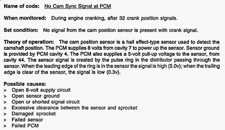
54= No cam signal detected. remove the distributor cap and see if rotor turns as engine is cranked. Code 54 DRB displays CRANKSHAFT SIGNAL SYNC PICK-UP SIGNAL. Condition is: no fuel sync signal detected during crankshaft rotation. Code 54 DRB displays NO CAM SYNC SIGNAL AT PCM. Condition is: open or shorted condition detected in cam sync signal circuit.
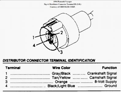
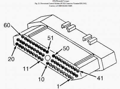
TEST TC-3A - NO CAM SYNC SIGNAL AT PCM (DTC 54) 1. Using DRB, erase trouble codes. Attempt to start engine. If engine will not start, crank engine for at least 20 seconds. Using DRB, read trouble codes. If DRB does not display NO CAM SYNC SIGNAL AT PCM, go to next step. If DRB displays NO CAM SYNC SIGNAL AT PCM, go to step 4). 2. At this time, condition required to set trouble code is not present. NO CAM SYNC SIGNAL AT PCM trouble code sets if Powertrain Control Module (PCM) does not see a camshaft position sensor signal with crankshaft position sensor signal present. Possible causes are: open or shorted crankshaft position sensor Orange wire, open crankshaft position sensor Black/Light Blue wire, open or shorted camshaft position sensor Gray/Black wire, damaged pulse ring, failed sensor, or failed PCM. Go to next step. 3. Inspect all related wiring and connectors. Repair as necessary. Perform TEST VER-2 . If wiring and connectors are okay, see INACTIVE TROUBLE CODE CONDITION in this article. Perform TEST VER-2. 4. Turn ignition off. Disconnect and inspect distributor connector. Repair as required. Perform TEST VER-2. If distributor connector is okay, go to next step. 5. Turn ignition on. Using DRB in voltmeter mode, check voltage of distributor connector (harness side) Tan/Yellow wire. If voltage is more than 4 volts, replace camshaft position sensor. Perform TEST VER-2. 6. If voltage is less than 4 volts, turn ignition off. Disconnect PCM connector. Using an external ohmmeter, check resistance of camshaft position sensor Tan/Yellow wire between distributor connector (harness side) and PCM connector terminal No. 44. 7. If resistance is more than 5 ohms, repair open in Tan/Yellow wire. Perform TEST VER-2. If resistance is less than 5 ohms, go to next step. 8. Using DRB in ohmmeter mode, check resistance of PCM connector terminal No. 44 (Tan/Yellow wire). If resistance is less than 5 ohms, repair short to ground in Tan/Yellow wire. Perform TEST VER-2. If resistance is more than 5 ohms, replace PCM. Perform TEST VER-2. NOTE: For circuit and connector terminal identification, see CONNECTOR IDENTIFICATION in this article. For wiring diagrams, see WIRING DIAGRAMS.
VERIFICATION PROCEDURE VER-2 1. Inspect vehicle to ensure all engine components are connected. Reassemble and reconnect components as necessary. If this test is being performed subsequent to a NO TROUBLE CODE test, go to next step. If this test is being performed subsequent to a TROUBLE CODE test, go to test 3). 2. Check if initial symptom still exists. If initial or another symptom exists, repair is not complete. Check if any pertinent Tech Service Bulletins (TSBs) apply to vehicle and return to TEST NTC-1A , if necessary. 3. If any trouble codes have not been diagnosed, go to TEST TC-1A and finish diagnosing other trouble codes. If all trouble codes have been diagnosed, go to next step. 4. If Powertrain Control Module (PCM) has not been changed, connect DRB to PCM Data Link Connector (DLC) and erase trouble codes. Using DRB, reset all values in adaptive memory. Disconnect DRB. Go to next step. 5. To ensure no other trouble code remains, turn on A/C and blower if equipped. Drive vehicle at least 5 minutes. While driving vehicle, attain a speed of 40 MPH. Ensure transmission shifts smoothly through all gears. After road test, turn engine off. Go to next step. 6. Start engine. Allow engine to idle for at least 2 minutes. Turn engine off. Connect DRB to PCM DLC. Using DRB, read trouble codes. If repaired trouble code has reset, repair is not complete. Go to next step. 7. Check if any pertinent Tech Service Bulletins (TSBs) apply to vehicle and return to TEST TC- 1A , if necessary. If another trouble code has set, go to TEST TC-1A. If no trouble codes are set, repair is complete. SUMMARY If no hard trouble codes (or only pass codes) are present, driveability symptoms exist or intermittent codes exist, proceed to appropriate TESTS W/O CODES - GASOLINE article in the ENGINE PERFORMANCE section article for diagnosis by symptom (i.e., ROUGH IDLE, NO START, etc.) or
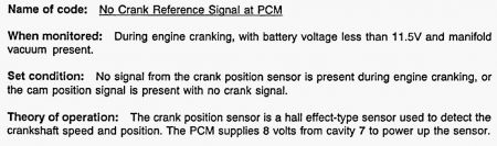
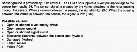
TEST TC-2B - NO CRANK REFERENCE SIGNAL AT PCM 1. Turn ignition off. Disconnect Powertrain Control Module (PCM) connector. Inspect PCM connector for damaged or pushed-out terminals. Repair as required. Perform TEST VER-2 . If PCM connector terminals are okay, go to next step. 2. Using an external ohmmeter, check resistance of Orange wire between distributor connector (harness side) and PCM connector terminal No. 7. If resistance is more than 5 ohms, repair open in Orange wire. Perform TEST VER-2. 3. If resistance is less than 5 ohms, place DRB in ohmmeter mode. Using DRB, check resistance of PCM connector terminal No. 7 (Orange wire). If resistance is more than 5 ohms, replace PCM. Perform TEST VER-2. If resistance is less than 5 ohms, repair short to ground in Orange wire. Perform TEST VER-2. NOTE: For circuit and connector terminal identification, see CONNECTOR IDENTIFICATION in this article. For wiring diagrams, see WIRING DIAGRAMS.
Thursday, September 24th, 2009 AT 4:31 PM