No power to the fuel pump?

Tiny
DAN ROB
  • MEMBER
  • 2013 NISSAN FRONTIER
  • 2.4L
  • 4 CYL
  • 2WD
  • MANUAL
  • 150,000 MILES
I replaced the fuel pump thinking it was bad. But there is no power going to it. Is there another relay besides the one in the fuse panel or something else that would cause the problem?
Do you
have the same problem?
Yes
No
Wednesday, November 16th, 2022 AT 2:02 PM

2 Replies

Tiny
JACOBANDNICKOLAS
  • MECHANIC
  • 108,014 POSTS
Hi,

That is the only relay. However, a few things have to happen for power to reach the pump.

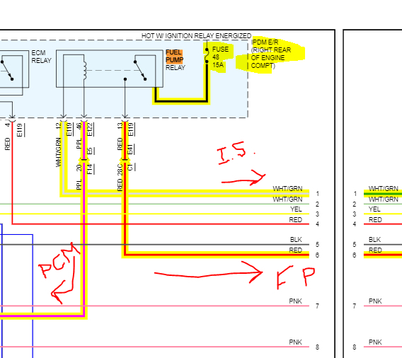
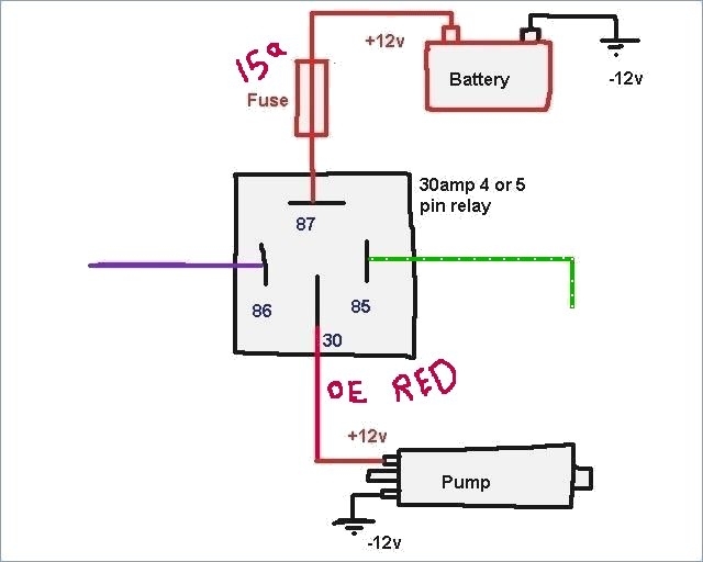
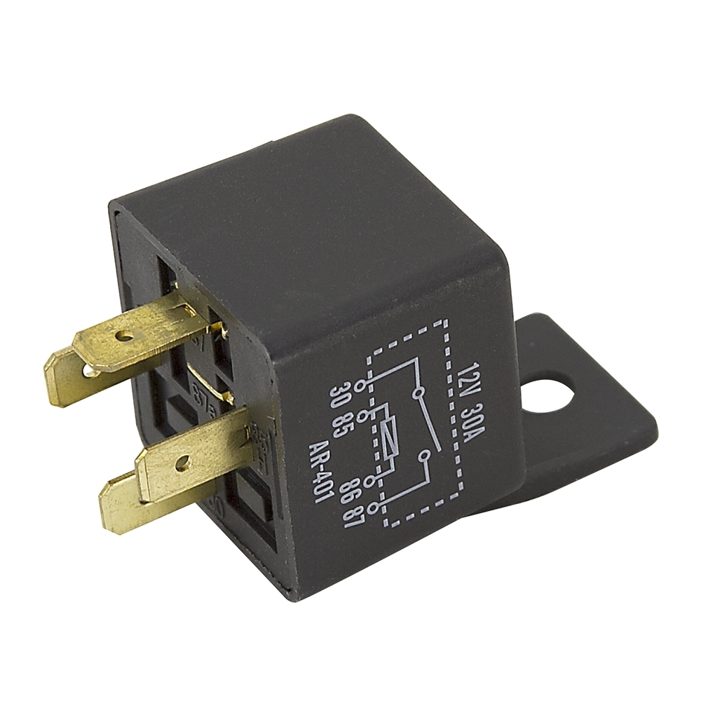
If you look at the attached pic, it shows the relay. Here is how it works.

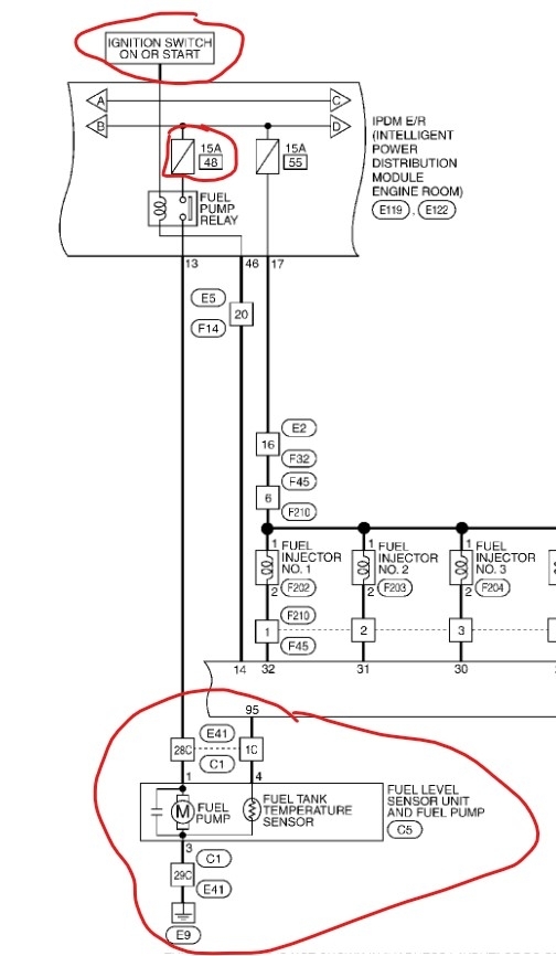
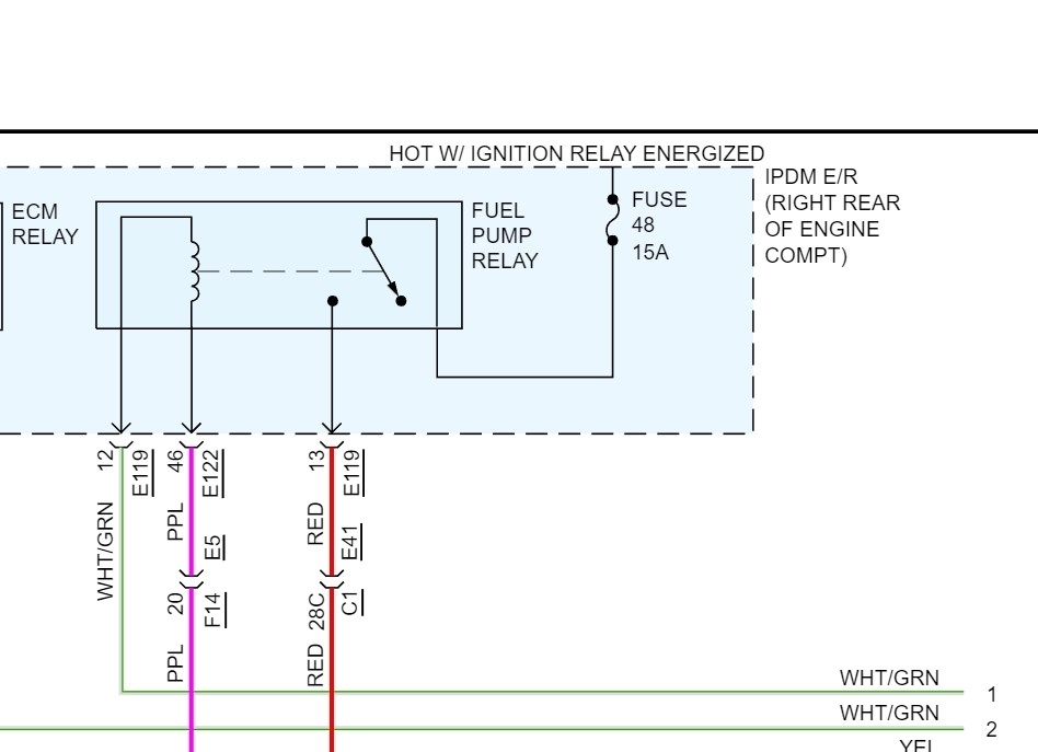
Fuse 48 provides power all the time to the relay, but the relay remains open until it is actuated. For that to happen, when you turn the key to run or start, power from the ignition switch goes to the relay via the white wire with a green tracer. At that point, the PCM needs to provide a ground path via the purple wire to complete the primary side of the relay.

When the primary side is powered, an internal electromagnet in the relay pulls the switch closed in the secondary side allowing power from fuse 48 to flow to the pump.

So, here is what we need to do. First, check to make sure fuse 48 is good and has power to and from it.

Here is a link you may find helpful:

https://www.2carpros.com/articles/how-to-check-a-car-fuse

Next, and the easiest thing to do, remove the relay and switch it with a different one having the same part number to see if that makes a difference.

If there is no change, then I need you to remove the fuse again. With the key off, there should be one pin in the relay box that has 12v at all times to the relay. Confirm that.

If that is good, I need you to check the white/green wire for power with the key in the run position.

If there is power, then confirm there is a ground path being provided by the PCM via the purple wire by checking continuity to ground.

If that exists, the red wire between the relay and the pump must be open (damaged).

Let me know what you find or if you have questions.

Take care,

Joe

See pic below. Sorry about the poor handwriting. LOL, I'm not too good with a mouse. The IS that looks like I5 indicates the ignition switch.
Was this
answer
helpful?
Yes
No
Wednesday, November 16th, 2022 AT 9:11 PM
Tiny
STEVE W.
  • MECHANIC
  • 12,883 POSTS
Attached is the OEM wiring diagram. Looking at it you should see power on the red wire and a ground on the black wire. The power feed comes from fuse 48 in the power center under the hood, it then goes through the relay and out to the pump. If you get no power to the pump with the key on, it could be the pump wiring or a bad relay or fuse or the relay isn't being activated by the ECM. Some easy tests to determine where the issue is, First verify that fuse 48 is good. Next you will need a test light connected to a good ground. Next you need to lift the integrated power module (fuse and relay box with fuse 48 in it) That way you can get to the red power wire at connector E119 pin 13 to connect the test light. Turn the key on, do you see the power pulse telling the pump to prime the system, it is normally about 1-2 seconds? If no pulse, there find the white with green stripe wire at pin 12 in that same connector. With the key on that should have power full time. If you have power, there but no pulse from the relay, take the test light and find the purple wire at pin 46 in connector E122 and gently touch it with the test light tip. If the pump powers on now the issue is in the ECM if it doesn't it is likely the relay inside the IPDM that is soldered to the board. If it's the relay you have two options, one is replacing the IPDM the other is to add an external relay and simply bypass the one inside the IPDM, I do a lot of those on various vehicles because it's easy and a lot less money. Some of them have removable relays but most are either soldered or crimped in. The unit is replaced by simply releasing the two tabs, lifting it up, disconnecting the electrical connectors and reversing the process with the new one. If you want to bypass the internal relay it involves cutting the three wires, adding the relay and a fused power wire to the replacement relay. I generally bypass the internal relay with a common 30-amp external relay wired similar to the last image. The relay gets mounted in a spot near the wiring, then a new 15-amp inline fuse gets added between terminal 87 and a power tap (usually right onto the stud that powers the fuse box. Then the power out to the pump goes from terminal 30 to the original red power to the pump. Next you attach the purple lead from the ECM to terminal 86 and the white with green wire from the switch to terminal 85. For those you will want to simply splice into those 2 wires as they may also switch other items inside the IPDM, so you don't just cut them. The red one going to the pump could also be spliced but it's optional. Now that relay takes over control of the pump.
However, you will want to test first as it's possible that the purple wire is the problem.
Was this
answer
helpful?
Yes
No
Wednesday, November 16th, 2022 AT 10:12 PM

Please login or register to post a reply.

Sponsored links