Code 27, no power to TBI injectors?

Tiny
BECKT
  • MEMBER
  • 1991 DODGE DAKOTA
  • 3.9L
  • V6
  • 2WD
  • AUTOMATIC
  • 64,000 MILES
The vehicle listed above has a TBI carburetor. Engine will not start with fuel injectors connected. When disconnected, the engine starts. Runs rough but it starts. Seems like something is forcing the injectors to stay closed. The injectors do click when I tap a nine-volt battery to the terminals. It also starts (with injectors connected) when the main fuel line is disconnected it runs fine until the carburetor is empty. I have an OBDC 1 code 27 also.
Monday, August 28th, 2023 AT 11:23 AM

19 Replies

Tiny
KEN L
  • MASTER CERTIFIED MECHANIC
  • 42,967 POSTS
In the context of a 1991 Dodge Dakota, code 27 refers to a "Injector Control Circuit." This code indicates an issue with the electrical circuitry related to one of the fuel injectors in the vehicle's engine. Fuel injectors are responsible for delivering the correct amount of fuel to the engine cylinders for combustion.

When code 27 is triggered, it usually means that there's a problem with the electrical signal or circuitry connected to a specific fuel injector. This could be due to a variety of factors, such as a faulty injector, a damaged wiring harness, a bad connection, or even issues with the Engine Control Module (ECM).

So, it sounds like your high resistance in one of the injectors, here is a guide to help you test them to confirm the issue:

https://www.2carpros.com/articles/how-to-test-a-fuel-injector

Please go over this guide and get back to us.
Was this
answer
helpful?
Yes
No
Monday, August 28th, 2023 AT 12:16 PM
Tiny
BECKT
  • MEMBER
  • 12 POSTS
So as the engine will not start some of these I cant do but,
* Observe audible clicking confirming injector operation.
Tested with 9-volt. Both click when powered

* Check trigger signal output from the PCM
as engine wont start cant do this

* Confirm the injector has power
No power from either side of connecting harness when key is on using test light probe to negative battery. I have verified continuity for the power leg from PCM Green/Black wire going to harness from PCM

* Test the coil windings resistance using a voltmeter
Both read 1.4 when set to Ohms
*
* Confirm injector valve operation
*
* Inspect the injector casing for leaks
Both seem OK visually

* Check flow and spray pattern
Hard to do as they have to be in the throttle body to pass fuel

The engine will run when the injectors are disconnected, rough but runs
Was this
answer
helpful?
Yes
No
Tuesday, August 29th, 2023 AT 7:13 AM
Tiny
BECKT
  • MEMBER
  • 12 POSTS
Disconnected the Throttle Kicker(?) And started right up. Reconnected it and seems to be working. Is this thing capable of shutting the whole system down like this? I do notice some chuffing now that wasn't there before.
Was this
answer
helpful?
Yes
No
Tuesday, August 29th, 2023 AT 7:43 AM
Tiny
BECKT
  • MEMBER
  • 12 POSTS
I still have no power to fuel injectors. Still throwing code 27. At least it starts now though.
Was this
answer
helpful?
Yes
No
Tuesday, August 29th, 2023 AT 1:29 PM
Tiny
KEN L
  • MASTER CERTIFIED MECHANIC
  • 42,967 POSTS
Any accessory like a fuel injector or ignition coil are idle kicker is shorted it will shut down the PCM. We should check the wiring connection between the injectors and PCM. here is a guide to help and the engine wiring diagrams below to help with the testing:

https://www.2carpros.com/articles/how-to-check-wiring

I would use this test with a voltmeter to check to see if any of the electronics is shorted out. Switch it to ohms and report back.

https://www.2carpros.com/articles/how-to-use-a-voltmeter

Check out the images (below). Please let us know how it goes.
Was this
answer
helpful?
Yes
No
Wednesday, August 30th, 2023 AT 9:59 AM
Tiny
BECKT
  • MEMBER
  • 12 POSTS
Okay, engine routinely starts now, right away, runs rough and some backfiring. Still no power to injectors. Using diagram, I have continuity form PCM harness on all lines going to injectors. Green/black for ground, white and blue for inj 1 and tan for inj 2. Still no power. I have probed into PCM connector with key on at those site. Nothing. Seems like PCM is not sending power.
Was this
answer
helpful?
Yes
No
Saturday, September 2nd, 2023 AT 3:14 PM
Tiny
BECKT
  • MEMBER
  • 12 POSTS
Further info. Tested the Idle speed control or throttle kicker as it called some places. Tested top pair got continuity and 18 ohms, bottom pair got continuity and zero ohms. Does this indicate a short? Also, no power to this either. Tested all pins in harness to ground and nothing.
Was this
answer
helpful?
Yes
No
Saturday, September 2nd, 2023 AT 4:25 PM
Tiny
CARADIODOC
  • MECHANIC
  • 33,752 POSTS
Hi guys. I'm waiting to learn the solution, but if it's okay, I'd like to add a few comments that might speed this along.

1. The power, (12 volts) you keep finding that's missing at the injectors is supposed to be missing. If you monitor that feed circuit with a test light, proper operation is for the light to turn on full brightness for only one second when you turn on the ignition switch, then it will go back off. That proves that circuit is working. The same circuit feeds 12 volts to the positive terminal of the ignition coil, to one of the alternator's smaller field terminals, and a number of other places including the fuel pump or a separate fuel pump relay. Checking this circuit with a digital voltmeter is not recommended as they respond too slowly. This 12 volts is coming from the automatic shutdown, (ASD) relay which is controlled by the Engine Computer.

Next, the ASD relay gets turned on again any time the computer sees engine rotation, (cranking or running). You're finding 0 volts at the injectors because you're not cranking the engine while testing for voltage. Other manufacturers have different names for the ASD relay, but they all have the same purpose. That is to stall the fuel pump if a fuel line is ruptured in a crash. If that happens, the engine can't run without fuel pressure. Since it stalls, the signal pulses from the crankshaft position sensor and the camshaft position sensor stop showing up at the Engine Computer. Lacking either of those signals is what tells the Engine Computer to turn the ASD relay off. Among all the other things, that removes the 12 volts to the fuel pump, so it doesn't dump raw gas on the ground through that ruptured hose.

I should mention too that there are different diagnostic fault codes that can be set related to those missing signals, but they take some time to be detected before a code will set. For that reason, don't automatically assume both sensors are working just because there's no code(s) set related to them. They often need more time, as when a stalling engine is coasting to a stop while driving, to be detected. A scanner is needed to see if those two signals are showing up when there's no related fault codes.

2. Don't waste your valuable time testing injectors. I've never known of anyone finding a bad one on a Chrysler gas engine, and even if you're the first one to run into one, you're definitely not going to find two at the same time unless they're plugged with a major contaminant, like sugar. If that happens, they'll still click when tested with a battery. The closest you'll find to an injector problem is on high-mileage GM engines. They will still pass any test you can think of, but over time they flow different volumes, leading to random or specific-cylinder misfire codes with an elusive solution. The engines seem to run fine.

3. There's something wrong someplace with your test method or your interpretation of the results. Regardless if you have one injector, two, or one for every cylinder, they must be pulsed with 12 volts to open. If they don't get 12 volts, no fuel will flow and the engine will not run. Since your engine is running at times, I have a suspicion that is not when you're checking for 12 volts at the injectors. If you check for it right after the engine stalls, there will be 0 volts then because the ASD relay turned off.

4. This is not a carburetor and there is no float bowl to run empty. What can make it look like the float bowl is running empty is the fuel in the line going to the throttle body is under pressure. If the fuel pump stops running due to its own problem, the engine can run for a few seconds until that pressure is bled off. A clue is the engine doesn't stop instantly. It gradually sputters to a stop over a few seconds as the fuel pressure goes down.

Throttle body systems typically run at around 14 psi for fuel pressure. When you have an injector for every cylinder, it's more common to find fuel pressure is around 45 to 55 psi. If you suspect a fuel pressure problem, there's usually a test port on the throttle body. When there isn't one, you have to disconnect the larger of the two fuel hoses and insert a temporary tee fitting to hook the gauge to. You can find fuel pressure gauge kits with all the fittings at any auto parts store that rents or borrows tools.

If you're unplugging the little black oval caps on the injectors to unplug them, the engine can't get fuel or run. If you're unplugging some other connector, such as one in a harness that goes from the body to the engine, I'd suspect the injector wires aren't in that one. The injectors have to be pulsing if the engine runs.

5. Since I'm sharing this wondrous information, let me include that the camshaft position sensor on the V-6 engines is the same as used in the 2.2L and 2.5L four-cylinder engines, and in this application it's called the "distributor pickup coil or assembly. On the four-cylinder engines, those had a very high failure rate; high enough that a lot of people carried spares in the glove box. When they fail, it's rarely an intermittent failure. They just quit completely. Due to its missing signal, the Engine Computer will not turn the ASD relay on during cranking, so you'll have a crank / no-start condition. With the ASD relay off, there's no 12 volts going to the ignition coil, so there's no spark. That's what way too many people get stuck on and they fail to look any further. They waste their time in the ignition system, and forget to check if the fuel pump is running or whether there's 12 volts to the injectors, (during cranking). Here again, there is often no fault code to tell you about the missing signal. Thet's when the scanner is needed to let the computer tell you whether it's seeing the signals from the cam and crank sensors. On the Chrysler DRB2 or DRB3 scanners, they are listed with a "No" or "Present" during cranking. When one stays on "No", that is the circuit that needs to be diagnosed. It is a failed sensor most often, but first the rest of the circuit, meaning wires and connector terminals, must be inspected.

You can find a DRB2 scanner on eBay for a few hundred dollars. There are a number of perfectly fine aftermarket scanners too, and they will have some similar way to show when those sensor signals are showing up. If you do choose to buy a scanner, I'd suggest posting a new question, and you'll get all kinds of dandy advice from the other experts. I have a DRB3 for all of my older vehicles, and it will do emissions-related tests on all brands of vehicles sold in the U.S. For everything else, I have a Snapon Solus Edge. If we get into a discussion on those, you can find really good deals on that model if it's not updated to current. Mine is only updated through 2018 models. That lowers their value a lot to independent shops, so you can pick one up for a fraction of what a new one would cost.

I hope that helps you with your diagnosis. I've never worked on a throttle kicker circuit and I've never run into that fault code. Most throttle body and sequential fuel systems use an idle speed "motor" to control idle speed. Those can only cause low idle speed. They won't cause a failure to run. I'll let you fine folks carry on and I'll be waiting to learn the solution.
Was this
answer
helpful?
Yes
No
Saturday, September 2nd, 2023 AT 6:32 PM
Tiny
BECKT
  • MEMBER
  • 12 POSTS
Okay, so I have replaced the Throttle kicker and the distributor pickup coil and seems to idle better. Starts right up, idles nicely but not drivable. Under any kind of load the engine sputters, backfires and revs drop and then stalls. I can make it out of the driveway about 20 feet before it quits. Starts right up and limps back to driveway. I have reset the codes a few times and now get a 22 and 27 consistently. 22 is the Coolant Temp sensor. It is getting 5 volts while engine running. Since it was cheap I've got one on order. I still suspect the fuel injectors are not working for some reason. Odd that they would both fail at the same time. Was running fine two months ago!
Was this
answer
helpful?
Yes
No
Friday, September 8th, 2023 AT 2:30 PM
Tiny
CARADIODOC
  • MECHANIC
  • 33,752 POSTS
Dandy observation on the coolant temperature sensor, but that shouldn't cause a problem either. For a '91 model, there will be two of them. One has a single wire. That is for the dash gauge only. The other one is for the Engine Computer and will have two wires. You should not find 5.0 volts there unless you check that with the connector unplugged. Instead, check the voltages by back-probing through the rubber weather seals alongside the wires. The readings are only valid when the connector is plugged into that sensor.

That circuit does start out inside the computer from the carefully regulated 5.0 volt power supply that runs most of the sensors. The difference with this one is there's a resistor inside the computer that "drops" some of that 5.0 volts when current is flowing through the circuit. What's left over is what you'll find where that wire leaves the computer and at the sensor's connector. That's the signal voltage. Typically you'll find somewhere in the area of 2.0 to maybe 4.0 volts. If you monitor it with your voltmeter, you'll see the voltage gradually dropping as the coolant warms up. If you want to stymie your friends, watch that voltage when the coolant gets somewhere around 160 to 180 degrees. That voltage will be down around 2.0 to 2.5 volts, then suddenly pop back up to around 3.5 volts, give or take, then start slowly dropping again. That's the temperature at which the computer is switching over to a different internal resistor so the sensor readings will have more precision at normal operating temperature.

Temperature sensors for liquids and air have extremely low failure rates because there's just one component inside them. There was one notable exception. In the early to mid '90s, Ford had a huge failure rate, but that had to be due to some type of manufacturing problem to have so many cause trouble. Other than those, well over 99 percent of problems in this circuit are due to corroded or bent connector terminals, or cut wires.

The diagram below includes the coolant temperature sensor. I added two arrows to show the two wires in the connector. Start by measuring the voltage on the tan / white wire, but remember, that has to be done with the connector plugged in. The two extremes that will set a diagnostic fault code are 0.0 and 5.0 volts. Those correspond to a cut wire, (or unplugged connector) or a break in the circuit further down the line. For explaining circuit theory, we customarily use 0.5 to 4.5 volts as the acceptable range for signal voltages. If you find anything within that range, you're done in this circuit. Every other part of the circuit, including the sensor, has to be working properly to get a reading on the tan / white signal wire that is within the acceptable range.

If you care to measure the voltage on the sensor's ground wire, Chrysler usually uses a black / light blue wire for sensor grounds. (That's black with a light blue stripe, or "tracer). Expect to find 0.2 volts on that one. That's because they don't go directly to a point on the engine or body sheet metal for ground. Instead, the grounds from most of the other sensors are all tied together, then they go through the Engine Computer on their way to ground. That's so the computer can monitor that circuit. That's also why there's two tenths of a volt there instead of 0.0 volts. If you were to find considerably more than 0.2 volts, there's a defect in that wire. We can narrow it down by finding if that same incorrect voltage is found at other sensors too or if it only affects the coolant temperature sensor. We'll cross that bridge when we have to.

Related to this, when you have a vehicle with an electric radiator fan, as you'll find on most front-wheel-drive models, you can quickly determine if the circuits are working by just unplugging this two-wire coolant temperature sensor with the ignition switch on the "run" position, with or without the engine running. Doing so will instantly be detected by the Engine Computer. It will set a diagnostic fault code, turn on the Check Engine light, and turn on the radiator fan. When you reconnect that plug, the fan will turn off within a few seconds. The Check Engine light might turn off, depending on model and year. If it doesn't, it will be off the next time the engine is started. If you don't erase the fault code, and you don't disconnect that sensor again, that code will self-erase after 50 engine starts. The system works that way because when there's a defect in the coolant temperature sensor circuit, the Engine Computer can't know coolant temperature. The fan gets turned on in case the engine is overheating.

For my final comment of value, I found why I never worked on a "throttle kicker" circuit.
They gave the part in question a different name for a couple of years. In later years it was called the "automatic idle speed" motor, or "AIS". GM uses the same part. You might find it called an "idle air control" motor or a few other names, but most of them, other than Ford's, work the same way. It's not a motor as you think of a spinning armature and brushes. Instead, there's four electromagnetic coils of wire that get pulsed with varying voltages and polarities by the Engine Computer. The armature follows the rotating magnetic fields, and as it rotates, it turns a threaded shaft. The total range for that shaft is about ten revolutions from fully extended to fully retracted. As it retracts, it opens a pintle valve that exposes more of an air bypass passage around the throttle blade. At the same time, the computer increases the number of milliseconds it pulses the injectors open. The increased air and fuel raise idle speed.

The computer can set that AIS motor to any of 256 positions, or "steps". For a properly-running engine, expect to find it at around step 32. With a single-cylinder misfire on a V-8 engine, it's typical to find it at around step 50.

Here's the important part you need to be aware of. With all the work you've been doing, there's a good chance you disconnected the battery or the Engine Computer at some point. Doing so erases everything the Engine Computer learned while you were driving. All of the sensor personalities and fuel trim data will be relearned as soon as you start driving again, without you even noticing. The one notable exception is "minimum throttle". Until that is relearned, idle speed will be too low. The engine may not start unless you hold the accelerator pedal down 1/4". It will not give you the nice "idle flare-up" to 1500 rpm at start-up, and it will tend to stall at stop signs. You'll have to drive with one foot on the accelerator pedal and the other working the brake pedal.

A very specific set of conditions must occur for the computer to know your foot is not on the accelerator pedal, then it takes a reading from the throttle position sensor and puts that in memory. From then on, every time it sees that same voltage, it knows it must be in control of idle speed. Those conditions occur when you go out and drive at highway speed with the engine warmed up, then coast for at least seven seconds without touching the pedals. At the end of that seven seconds, minimum throttle will be learned and the computer will be in control of idle speed.

If you were to look at the "AIS Steps" on a scanner, it will show "step 0" when minimum throttle hasn't been learned yet. For most people this low idle speed problem seems to magically fix itself, and they don't know why, but it's because the conditions needed can typically be met by coasting halfway down the typical off-ramp.

For your viewing pleasure, I added the second diagram that shows the AIS motor at the top. "Throttle kickers" used to be a two-wire solenoid that pushed the throttle blade open a little on carburetors. This circuit is entirely different in circuitry and operation, but they kept the name to be sure we'd be confused. It's just the standard, common circuit that was used until they switched to "throttle-by-wire" systems in the mid 2000s.
Was this
answer
helpful?
Yes
No
Friday, September 8th, 2023 AT 7:32 PM
Tiny
BECKT
  • MEMBER
  • 12 POSTS
So, on a whim I stuck my finger down in the carburetor to see if I could feel fuel from the injectors. Should have done this earlier. One is working, one is not. Explains why drives so bad. Anyway, swapped out the injectors and sure enough same side not working. So it's a wiring issue. Started playing around with the connector while it was running and that seems to be the problem as it will die with certain movements. I know the wires are good cause I checked them all and the throttle body harness is in great shape. I think the connections inside the connector housing are bad, corroded or loose. Going to try to disassemble it and see. Prob have to cut a new one in as they don't seem to be available anymore.
Was this
answer
helpful?
Yes
No
Friday, September 8th, 2023 AT 8:18 PM
Tiny
BECKT
  • MEMBER
  • 12 POSTS
After cutting in a new 4-way connector the issue remains. With the new connector wires are big enough to back probe. With test light to neg terminal on battery I get light-up on all but one of the 4 wires and that one does go to the one not spraying. It has good continuity from PCM 60-way connector, so either that pin is not making good contact or the PCM simply isn't powering/using that wire. Could the PCM fail that narrowly? Everything else seems to be working as it should. Do both fuel injectors spray all the time or does the second one come in on demand/load? Ugh!
Was this
answer
helpful?
Yes
No
Saturday, September 9th, 2023 AT 9:47 AM
Tiny
CARADIODOC
  • MECHANIC
  • 33,752 POSTS
Both injectors are fed with the 12 volts coming from the ASD relay. The Engine Computer grounds each one on individual ground wires to fire them. Both fire at the same time, and each one feeds one side of the engine.

For the throttle body injectors I remember working on years ago, you could see the cone-shaped spray pattern under each one.

What you found reminds me of a friend who ran into this with a Chevy Astrovan about 15 years ago. He too could see the spray missing from one injector. Funny thing was it only acted up when it was raining. The black connectors looked like half of a hard-boiled egg. When he pushed on one, the spray returned and the engine ran fine.

Rather than trying to replace or disassemble the connector, the typical place to start is by picking the connector terminals with a skinny metal pick. Try to squeeze the two sides of the terminals in the connector so they make a tighter contact. The injectors will have two tips sticking up, kind of like the tip of a ball point pen. Scratch those lightly a little with fine sandpaper to remove any light film of corrosion. As a last resort, you can bend those very slightly so they make tighter contact against the terminals in the cap. Another thing to try is squeezing those pins with a larger needle nose pliers to make them oval-shaped. That can make them fit tighter too.

Keep us up to date please on your progress.
Was this
answer
helpful?
Yes
No
Saturday, September 9th, 2023 AT 5:32 PM
Tiny
BECKT
  • MEMBER
  • 12 POSTS
I suspected the cap connection was not making contact with the injector, but wouldn't the fact that I get no voltage on one line before the cap mean the failure is further up the chain? Or would bad contact prevent circuit completion and therefore nothing on that line?
Was this
answer
helpful?
Yes
No
Saturday, September 9th, 2023 AT 6:07 PM
Tiny
CARADIODOC
  • MECHANIC
  • 33,752 POSTS
Your second guess is correct. 12 volts appears on one wire, coming from the ASD relay. If that connector is unplugged, that's the only wire you'll find 12 volts, but again, that's only for that first one second when the ignition switch is turned on, and during engine rotation, (cranking or running).

When it's plugged in, the 12 volts makes it through the injector's electromagnetic coil and shows up on the other wire. In fact, that 12 volts will be found all the way back to the computer. I drew red lines to show the current path. This part of the circuit actually starts in the second diagram where it leaves the ASD relay. You can see all the other places it goes, including the ignition coil and fuel pump, but the part we're interested in goes to the left and continues on the first diagram. From there, it goes to both injectors. The 12 volts ends there when those connectors are unplugged.

In the third diagram, the connectors are plugged in. Now the 12 volts shows up all the way to the computer on the brown and blue lines. I used different colors because these are the two lines the computer will ground when it wants to pulse the injectors. It uses a pair of transistors to do that. In this application, the transistors are used as simple on / off switches. When the transistor is switched on, it in effect, shorts that line to ground.

One problem with diagnosing this type of problem is I never allowed my students to pierce a wire's insulation to take a reading. Also, it's too difficult to back-probe wires in most computer connectors, so there's no easy way to know if you're getting 12 volts all the way to the computer. If the terminals aren't making a good contact in the injector's connector, that 12 volts WILL be missing on the brown or blue circuit and that injector won't fire. Fortunately, we have other ways to diagnose a bad connection, and you already found it. That's to just wiggle, poke, or irritate the plug while observing the poor or good engine performance.

I've never had to repair one of these myself, but there's usually a way to get a pick in alongside the terminal in the cap to squeeze it tighter. You'll want to do that to both of them in that connector. A bad connection with either one will cause the same problem.

There's one more way to approach this that I didn't mention yesterday, and it should be considered a last resort. If you're good at soldering, that is to dribble a little solder on the two terminals on the injector. Don't get carried away. The idea is to build up their diameter just a little so they'll fit tighter in their mating terminals in the plug. Regardless how much fatter they become, that is going to stretch the connector's terminals even more. They'll make a better contact now, but if you would ever have to replace that injector, you're even more likely to run into a bad connection. Only do that if nothing else seems to work.

After rereading your last comment about having no 12 volts before the connector, I suspect you were checking that with the engine not rotating. The ASD relay will be off then, so you would indeed find 0 volts throughout the system.

If you were checking that with the engine running poorly on one injector, we know the ASD relay has to be on and 12 volts is making it to the one firing injector. In that case, if you removed the connector for the dead injector so you could measure, and you did find the 12 volts missing, the suspects would be a cut dark green / black wire back as far as the splice, or a corroded splice itself. A cut wire isn't a good suspect because that isn't likely to work intermittently. A corroded splice can cause intermittent operation and would be the better suspect. If the splice appears to be something you want to go after, I'll try to find the drawing that shows its location so you don't have to tear the entire harness apart.
Was this
answer
helpful?
Yes
No
Sunday, September 10th, 2023 AT 6:49 PM
Tiny
BECKT
  • MEMBER
  • 12 POSTS
It was indeed a non-contact situation with the injector. I squeezed it a bit to get contact and now have voltage on all 4 lines and both injectors spraying. Still have code 22 and 27 though. Drove great all the way to the lumber yard and then wouldn't start coming back. Acting the same way, it did at the start of this. Disconnected the fuel injectors, started and shut off. Reconnected and it started up fine. It did the same thing when I got home. Wont re-start when hot. Waited a few hours and it started right up. Is this the temperature sensor (code 22) causing this?
Was this
answer
helpful?
Yes
No
Monday, September 11th, 2023 AT 8:56 AM
Tiny
CARADIODOC
  • MECHANIC
  • 33,752 POSTS
Coolant, air, and battery temperature sensors won't cause a crank / no-start condition. The type of failure you're describing is how crankshaft position sensors and camshaft position sensors commonly fail on all car brands. They typically work fine while you're driving and natural air flow keeps them cool. When a hot engine is stopped, engine heat migrates up to the sensors causing one to fail. They become heat-sensitive, then they work again after cooling down for about an hour.

The frustrating part is it takes the Engine Computer some time to detect the missing signal, as when a stalling engine is coasting to a stop. Often simply cranking the engine doesn't provide the conditions to see the defect or set a diagnostic fault code. For that reason, don't assume those sensors are working just because there's no code set related to them. When that happens, we need a scanner to view live data and let us see what the computer is seeing. Both sensors will be listed with a "No" or "Present", or something similar, to show if the signals are showing up. We want to see both switch to "Present" during cranking. If one does not, that is the circuit that needs to be diagnosed.

With other fault codes that make reference to a sensor or other part, that part is the cause of the code only about half of the time. First we have to rule out wiring and connector terminal problems, and mechanical problems related to that part. I think I mentioned earlier that your camshaft position sensor design has had a very high failure rate in the four-cylinder engines. The 3.9L uses the same design, so if you're going to try a new part, start with that one. It's a plastic disc under the rotor in the distributor.
Was this
answer
helpful?
Yes
No
Monday, September 11th, 2023 AT 10:27 AM
Tiny
BECKT
  • MEMBER
  • 12 POSTS
I replaced that a while back. Pickup coil. The only thing left seems to be the TPS and the MAP sensors.
Was this
answer
helpful?
Yes
No
Monday, September 11th, 2023 AT 2:15 PM
Tiny
CARADIODOC
  • MECHANIC
  • 33,752 POSTS
We don't want to throw random parts at a problem. That's the most costly and least effective way to diagnose a problem. The far better alternative is to look on eBay for a Chrysler DRB2 scanner. They're often available for a couple of hundred dollars, but if you've never used a scanner, you'll be amazed at what you've been missing.

There are a few things to be aware of. First, these need a plug-in cartridge that covers the vehicle you're working on. There were dozens of them, including for the Mitsubishi-built models. It isn't practical to try to find every cartridge that was available. Instead, toward the end of their reign, Chrysler came out with "Super cartridges" that covered all models. The first one I recall was in 1993. It had a blue label to match the color of the service manual covers for that year. Next was one with a yellow label for '94 models. That is the Super cartridge to look for. Nothing changed for the '95 models so you use the '94 cartridge for every Chrysler product from '95 back to '83.

Once you have the scanner and an appropriate cartridge, there are two cables. The main one has a square plug with a corner notched out, and six terminals. That's used for the Engine Computer, which is what we need now. The other cable has a smaller rectangular plug, also with six terminals. It plugs into a blue connector behind the inside fuse box cover left of the driver's knees, or on the right side of the center console, under the dash. That one's for the ABS, Air bag, and, as I recall, the Transmission Computer when you have one. We don't need that cable for this problem.

The problem with the DRB2 is they only work on '83 through '95 models. I also have a "Monitor 4000". That's the aftermarket version, but it looks very much like the DRB2, uses its own cartridges, and was built by the same company that built the DRB2 for Chrysler. You can find these on eBay too. There's a lot of other brands of older scanners, but these are the ones I'm familiar with. The advantage of the Monitor 4000 is one cartridge covers all GM, Ford, and Chrysler models up through the year the cartridge was made. Mine only goes to '92 or '93 models. I also have a separate anti-lock brake systems cartridge, but I never plugged it in to try it. The advantage of the DRB2 is it does everything the engineers wanted us to be able to do. The Monitor 4000 doesn't do quite as much, but it does it on more car brands.

If you want to step up and don't care about cost, look for a Chrysler DRB3 on eBay. The entire kits used to cost $6200.00 through the manufacturer's web site, but I paid close to half of that by going through the parts department at the dealership I used to work for. Today they still bring around $2000.00. Depending on the year they were made, they work on models back to '96 or to '98 directly, and up to the last years they covered. The first models to be obsolete was the 2004 Dakota / Durango. The last models were some 2008 Jeeps. They could use an entirely different type of plug-in cartridge that would let you work on older models. Depending on the cartridge, one let it work on models back to '94, and it let you do emissions-related stuff on all car brands sold in the U.S. Starting with '96 models. A different cartridge let you work on '83 through '93 models. That's the one you would need for your truck. There's three cables for the DRB3. The main one is the trapezoidal one used in all cars now starting with '96 models. The other two have the same connectors as those two for the DRB2. Because of their ability to work on emission system problems on all car brands, a lot of independent repair shops bought them. Since they're long obsolete now, many of those shop owners are happy to sell them so they can invest in something newer. That's why a lot of these show up on eBay.

Next would be a higher-end aftermarket scanner. My friend and I each have a Snapon Solus Edge, but mine is only updated through 2018 models. The disadvantage of these is the cost of annual updates is very high; so high, in fact, you're better off just buying a new model every five to six years. The advantage for you and me is they lose their value to repair shops when they get a few years out of date. As long as mine works on my two 2014 models, that's all I need, but it lowers their value, so you can find these as low as around $700.00. No cartridges needed or used with this model, but for anything older than a '96 model, you need a different cable and the correct connector for the vehicle you're working on. Those connectors, (Snapon calls them "adapters"), are very reasonable on eBay. I bought over a dozen cheap ones just to have, even though I'll likely never use them.

I just ordered a new Autel scanner last week based on a glowing review by one of our other experts. Cost was less than $1300.00 and it comes will all kinds of connectors to fit just about any brand of car and light truck. I'll know more about that one soon.

The point of this story is we're spinning our wheels from not knowing what your Engine Computer is seeing and responding to. This is like a new doctor who hasn't invested in a stethoscope yet. We need to address the coolant temperature sensor problem yet, but that can wait until we solve the running problem.

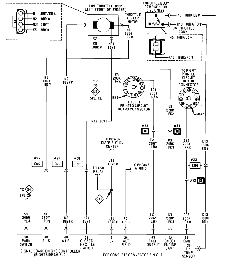
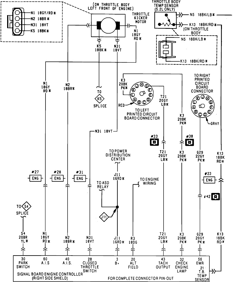
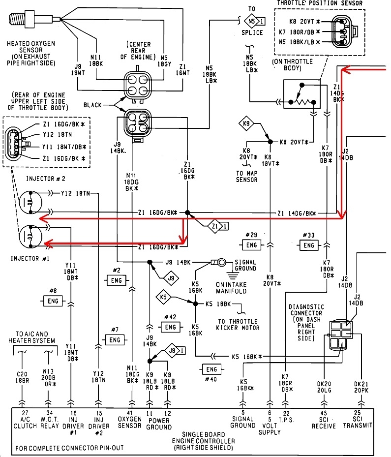
To address your comment about the last two sensors, the throttle position sensor tells the Engine Computer five things. When you're at closed throttle, (idle), when you're at wide-open-throttle, (clear flood mode), throttle position, direction of change, and rate of change. This sensor is the least important one for proper engine operation. In a very rare instance, it can cause a crank / no-start, as it did on my '94 Voyager, but that was so unusual, I know I'll never see that again. Normally, at most, it will cause a very slight hesitation when you want to accelerate. You can monitor the voltage on the signal wire with a digital voltmeter. This sensor has mechanical stops that limit how far they can read. The numbers can vary a lot, but for training and explanation purposes, we typically use the range of 0.5 volts at closed throttle, to 4.5 volts at wide-open throttle. (I commonly find 4.2 volts to be the highest they'll read). The important point is anything outside that range is what gets detected by the computer as a defect, and triggers a diagnostic fault code.

When you watch that signal voltage sweep up and down as you work the accelerator pedal, digital voltmeters update their readings rather slowly, as in a few times per second. You can watch the same voltage on the scanner. For some years now there are very inexpensive units on the market that are called "scanners", but while they can show you much of the same data, they update painfully slowly, as in once every four to five seconds. One thing we always want to watch for is a "dropout" where the voltage is rising smoothly, then suddenly drops to 0.0 or 5.0 volts for just an instant. You'll never see that with these inexpensive units. You are unlikely to see that with a digital voltmeter. And there's a good chance you won't catch it with a more expensive scanner. The Engine Computer is the only thing that's fast enough to catch many of these dropouts. It will set an appropriate fault code that will tell us where to start the diagnosis. Without the scanner to show you what the computer is responding to, you're stuck with guesses and trial and error methods.

By the way, my TPS did cause that crank / no-start, but for the previous owner, it caused a very intermittent failure of the transmission to upshift normally. It was not in "limp" mode that keeps it in second gear. It was in the shop three times for that but no one could make it act up, and there were no fault codes set to tell anyone what was happening. I figured out it was the cause of both problems once I made it back home and connected the DRB3. Within a minute I saw the readings from the TPS were well within the acceptable range of 0.5 to 4.5 volts, so no fault code was set, but the readings were wildly wrong. The TPS would stick at a higher reading which told the computer I was requesting clear flood mode. In response, the computer stopped firing the injectors, hence the crank / no-start. As soon as I pressed the accelerator pedal all the way to the floor, then released it, the TPS signal voltage followed it back down to 0.5 volts like it was supposed to, then the engine would start right up. There's no way I or anyone else would ever have figured that out without a scanner. The Transmission Computer interpreted that too-high TPS voltage as I had it floored to take off from the stop light, so it was delaying the up-shifts to a higher road speed like it was supposed to do, except I wasn't really going that fast.

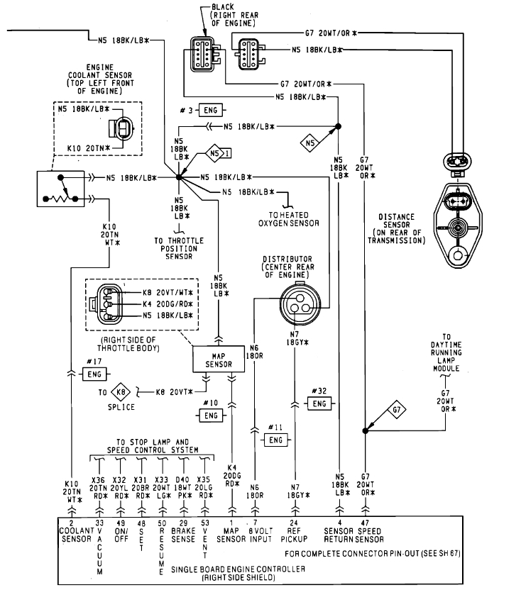
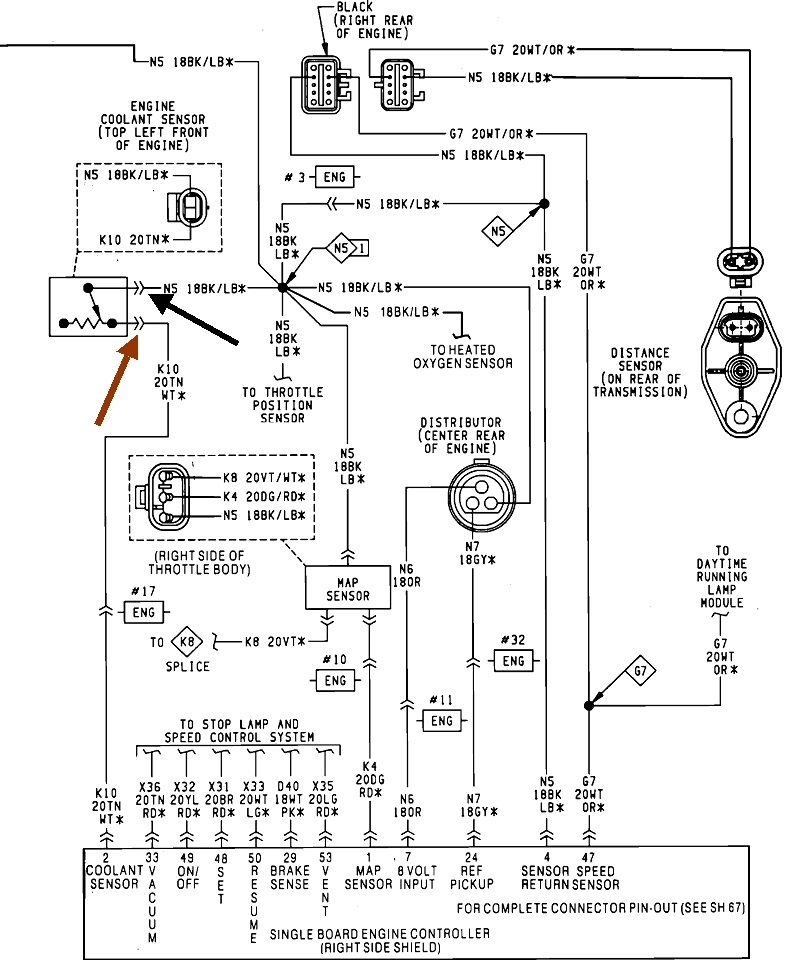
The MAP sensor IS very important for fuel metering calculations. On all other car brands, a mass air flow sensor is used to measure the weight of the incoming air, then the computer figures out how much fuel to request to go with that air. According to some national instructors, "Chrysler was the only manufacturer that could make an engine run right without a mass air flow sensor". The MAP sensor was what Chrysler used for many years. It simply measures intake manifold vacuum to calculate engine load, but right after the ignition switch is turned on, and before the engine starts running, it also measures barometric pressure. This sensor works very differently than the TPS, and it has circuitry inside, but the range of signal voltages it puts out is again, 0.5 to 4.5 volts. Besides electrical problems with this sensor, the computer can also detect pneumatic problems with it. We were taught they do not use this sensor to measure engine speed, but they could if they wanted to because they're so sensitive, they see every tiny pulse of vacuum change each time an intake valve opens and a piston takes a gulp of air. If we were to see the MAP sensor putting out 2.3 volts, for example, and we tried to replicate that with an adjustable power supply, the Engine Computer would set this pneumatic-related fault code because it didn't see the tiny ripple in the voltage readings. That could correspond to a kinked vacuum hose going to the sensor that prevented it from responding fast enough. There was a real problem on the older K-cars where there was a droop in one section of that vacuum hose, and fuel vapors could condense there and dampen the voltage fluctuations to the point the computer would set the MAP pneumatic code.

To add to the misery, GM developed this MAP sensor and had a huge problem with them, ... So they sold them to Chrysler. That's the way the story went in one of the classes I attended. Of course Chrysler had all kinds of failures too, including on my '88 Grand Caravan. There's more to this story, but once that sensor was redesigned by the early '90s, failures were very uncommon. It's very unlikely one of those of the original design is still around. Problems today are more likely to be caused by a dry-rotted vacuum hose going to that sensor. If you want to try a different one, since the failures now are so low, I'd grab one from a vehicle in a salvage yard. The same part was used over many models through many years. Since you don't have a fault code set related to this sensor, it really is not a good suspect.

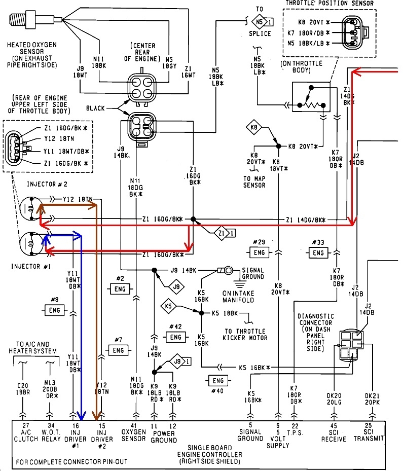
If you have an engine that stalls after it gets warm, especially if it occurs right after stopping a hot engine, as in when stopping for gas, the first thing to do is check for spark. If that's missing, about 95 percent of the time you'll be missing injector pulses and fuel pump too. The fuel pump will still run for that initial one second, so pressure readings will appear to be normal.

As a final point of interest, I got called to my friend's shop today to help with a 2001 Ram 3500 that ran fine the last time it was run two months ago, but now is a crank / no-start. Everything appeared to be working, but it did try to run when we sprayed gas into the intake. Turned out to be sugar in the tank. We ran the fuel pump to empty the tank, then five gallons of new gas had it running in less than a minute. Appears to have no clogged injectors or filters, but there's a lot of steam from the water we used to put out the two fires. Fortunately, neither of us lost any eyebrows.

Will wait to hear what you find next, then we'll see what else we can come up with.
Was this
answer
helpful?
Yes
No
Monday, September 11th, 2023 AT 9:54 PM

Please login or register to post a reply.

Sponsored links