Headlights are not working?

Tiny
RD66
  • MEMBER
  • 1985 CHEVROLET S-10
  • 2.3L
  • V6
  • 2WD
  • MANUAL
  • 1,000,000 MILES
At first the high beams flickered after they heat up. Low beams worked okay.
But now there's no headlights at all.
No power on the alternator post wire. The small brown wire on the alt plugin terminal has power until its plugged into the alt. Multimeter says the battery is charging. It has new headlights and dimmer switches. The fuses are all good.
The ground seems to be good.
Any suggestions would be helpful.
Thursday, March 23rd, 2023 AT 11:46 PM

15 Replies

Tiny
CARADIODOC
  • MECHANIC
  • 33,752 POSTS
In over 40 years of repairing tvs, vcrs, car radios, and cars, I can honestly say I have never seen more miserable or less useful wiring diagrams. I posted them below for you to see for yourself. I'm going to work on cutting these up into pieces so I can expand them. In the meantime, I have a couple of observations.

First, if you found 0 volts on the generator's output stud, how can the system be charging the battery? Tell me the exact voltages you find across the battery terminals with the engine off, then again with it running.

Second, I have an explanation for why you're finding two different voltages on the brown wire depending on whether it's plugged in or unplugged. You'll get a different reading with it unplugged if you use a test light. In fact, use your voltmeter, see what you have there with the ignition switch in the "run" position, then leave it connected, but add the test light right next to it. You should see the voltage drop to roughly 6 volts when both the voltmeter and test light are measuring on that brown wire. Also check on the other small wire in the plug. It should have full battery voltage all the time.

To be valid, all voltage measurements must be taken with the connectors plugged in. When you do that, and the ignition switch is in "run", you will see the "Battery" light on the dash is lit up. If it is not, that is a separate problem we will need to address.
Was this
answer
helpful?
Yes
No
Friday, March 24th, 2023 AT 5:00 PM
Tiny
CARADIODOC
  • MECHANIC
  • 33,752 POSTS
Okay, here's the first half of the diagram cut into 12 pieces. The first four are across the top. The last four are along the bottom, left to right. Guess where the other four go.

I'm going to work on the second half of the diagram at home and will post that tomorrow if it is relevant. I also want to study the headlamp circuit before deciding where to start the diagnosis. I suspect we will need to get at the wires on the headlight switch. Check the old switch for black, burned, charred, or discolored terminals, and check if any in the plug are burned or the plastic around them is melted.
Was this
answer
helpful?
Yes
No
Friday, March 24th, 2023 AT 6:10 PM
Tiny
RD66
  • MEMBER
  • 61 POSTS
Hello, Mr. Caradiodoc, I guess I should have made it clear when I said there was no voltage on the alt post wire. The wire that goes to the alt post has no voltage. So, I ran a temporary wire from the battery to make it charge. Now i'm trying to figure out why that wire is dead. Actually, I changed that headlight switch, but I don't think there was a problem with it. There were no burns on the switch or the plugin. When I changed the switch or now. The wire next to the brown wire on the terminal plugin does have full voltage at all times. I do have another question. Can the alternator be charging but still be bad? When I first crank the truck the volt gauge says its discharging until I rev up the engine a bit, then it jumps up to about 14.4 Thanks for the diagrams, I will get into them and see what I can figure out if anything. Thanks for your help.
Was this
answer
helpful?
Yes
No
Friday, March 24th, 2023 AT 8:08 PM
Tiny
RD66
  • MEMBER
  • 61 POSTS
Was this
answer
helpful?
Yes
No
Friday, March 24th, 2023 AT 8:18 PM
Tiny
CARADIODOC
  • MECHANIC
  • 33,752 POSTS
I can answer all of your questions. First, here's the second half of the diagram for your truck, cut into 12 pieces like the first half I posted yesterday. If you care to print out these 24 diagrams and put them together, you'll have the complete wiring for your truck.
Was this
answer
helpful?
Yes
No
Saturday, March 25th, 2023 AT 2:17 PM
Tiny
CARADIODOC
  • MECHANIC
  • 33,752 POSTS
I formatted and typed all through last night. I'll cover the missing 12 volts on the generator's stud shortly. To avoid confusion on my part, I'm going to post the diagrams here first. Don't worry if you can't follow them. I tried to cover everything I could think of so you would have all the information you might need, rather than wait for me to return each day. Just go as far as you can, let me know what you find and when you get stuck, then I'll figure out your next step. Here's what I typed up last night:

Working back from the headlights, the left one is shown in the first diagram. Based on the fact both low and high beams are dead, we can look at either circuit. I picked the low beams to find my way back to the headlight switch. The circuit is highlighted light pink. Since both lights are dead, the problem can't be located in this section. It has to be located in a section both lights have in common. That would be the dark pink circuit that starts at the right headlight, (second diagram). Follow this circuit through the third, fourth, and fifth diagrams to the connector. This is one part of the bulkhead connector on the firewall. It's impossible to read, but that is terminal # 12.

The light green dashed line takes us to the other half of the connector. The circuit continues to the right, then through the sixth and seventh diagrams, to the eighth diagram. This gets a little tricky by the dimmer switch on the far right. It's also on the left side of the ninth diagram. Everything up to this point is not suspect because a defect in this circuit would not affect the high beams.

The headlamp feed circuit is common from here back to both the low and high beam circuits. It's highlighted in yellow. The break in the circuit has to be before this point, to include the dimmer switch. The dashed green line takes us from the connector to the headlight switch layout, and back to the 12-volt feed, red wire. This is where we have to look for a major clue. Do the running lights, tail lights, and / or dash lights work? Those circuits get their 12-volt feed from the same red 12-volt wire that feeds the headlight circuit. If those other lights work, there's no need to look further back toward the fuse box and battery.

Tail lights do work:

If the tail lights do work, the problem has to be between the headlight switch and the dimmer switch. Start with the yellow wire on the headlight switch connector. You should find 12 volts there when the switch is in the "headlight" position. If it is not there, the switch is defective or the wrong part. This is also one of the terminals that will be blackened or discolored if it overheated previously. If you have the option, use a test light for these tests instead of a voltmeter. It is faster and can be more accurate in this type of circuit. This part of the circuit starts on the ninth diagram, yellow wire.

If you do have 12 volts, the next test point is that wire on the dimmer switch. Normally there is a large connector with this wire in it at the base of the steering column, but that isn't shown on this diagram. Those mating connector terminals are another common source of overheated / burned terminals. If you can find that connector and the yellow wire, check on both sides for 12 volts with the headlight switch turned on.

Since you mentioned the lights were flickering at one point, there are three common things that points to. The first is those overheated terminals. Those can be at a switch connector or at an inline connector like the one at the base of the steering column. Next is arced or pitted contacts inside the dimmer switch. The clue there is most often the high and low beams don't fail at the same time, or one of them will still work intermittently for a while. The last thing is the headlight switch itself. The contacts rarely cause the problem because they slide over each other to perform a scrubbing or cleaning action. Instead, they have an auto-resetting thermal circuit breaker that does develop pitted contacts. That creates resistance which translates into heat which helps the circuit breaker to trip or arc. Those reset pretty quickly, but arced surfaces can prevent them from passing current. When the circuit breaker is at fault, you'll have the 12 volts on the red feed wire, but not on the yellow headlight wire. The switch must be replaced to solve that. The circuit breaker is built in and is not serviceable.

Tail light do not work:

When none of the lights work, we have to work back to the fuse box. In the mid '80s, GM was experimenting with aluminum wires. That has also caused a real common problem behind the fuse box. The wires are riveted to the brass buss bars with brass rivets. Two different metals with an acid causes "galvanic action", or corrosion, similar to the chemical reaction in a battery. Road salt gets in the area of the fuse box. That is the acid that causes the corrosion.

This red feed wire goes back through the eighth, then the seventh diagram, the tenth and 11th diagrams, then back through the bulkhead connector in the 12th diagram. Those terminals are another good suspect. Check for 12 volts on both sides. It should be there all the time.

Finally, in the 13th diagram, this circuit originates with a fuse link wire connected to the large battery cable terminal on the starter solenoid. The starter motor is not involved with this circuit. GM just used that terminal as a convenient tie point rather than running this wire all the way back to the battery. If the fuse link wire is burned open, that red wire is likely grounded. The fuse link won't cause flickering lights. Once they burn open, they're done, just like a regular fuse. A wire rubbing or shorting to ground intermittently will cause flickering until the fuse wire finally burns open. Test this fuse link wire by gently tugging on it. If it's good, it will act like a wire. If it's burned open, it will act like a rubber band. For some reason, this wire gets overlooked quite often when replacing the starter. It is also not uncommon for the wire to corrode off on one end.

Do not eliminate the fuse link wire. Splice and solder it like any other wire. It is a regular wire that's a smaller diameter than the wire it protects, so it's the weak link in the chain. The insulation is what makes it special. It is designed to not melt or burn. You can buy replacement fuse link wire at any auto parts store. The color denotes its current rating. You'll get a piece about 12" long. That's enough that it can be cut to make two or three repairs.

If you do find the fuse link is burned open, I have a procedure for locating the short before you replace it. A replacement is likely to burn open again if the short isn't repaired first. That's too much work to go through to see it burn out again.

Let me know what you find or where you get stuck.
Was this
answer
helpful?
Yes
No
Saturday, March 25th, 2023 AT 2:48 PM
Tiny
CARADIODOC
  • MECHANIC
  • 33,752 POSTS
If you look way at the top of the 13th diagram above, you'll see the fuse link wire for the circuit I highlighted in red. Right above that is another fuse link wire. That part of the diagram is cut off on the bottom, but that is the wire that goes to the generator's output stud. If you did not disconnect that wire at the generator when you added your bypass wire, and that added-on wire isn't getting hot, AND the system does charge the battery, it's a good bet that original wire is not shorted to ground. Instead, the better suspect is the wire is corroded off at the starter solenoid or was forgotten / overlooked when work was done by the starter. Check those two fuse link wires by the starter and tell me if either is burned open or corroded. The type of failure will tell us the likely cause.

Next, with Fords and GMs, observe if the "Battery" light on the dash turns on when you turn on the ignition switch. Current goes through that bulb, then through that brown wire plugged into the side / back of the generator in the two-pin plug. That current is the turn-on current that wakes up the generator's internal voltage regulator and gets it started. If that light is on, there's actually only about 10 volts that gets dropped across it. You'll find the other 2 volts on the brown wire, but only when the connector is plugged in. This is where I mentioned these voltages are only valid when connectors are plugged in. You'll need to understand basic electrical theory for this explanation. If you do not, don't worry. We'll still get through this.

When you unplug the two-wire connector, and then take the voltage reading on the brown wire, there won't be any current flow. (Digital voltmeters can be compared to a pressure gauge on a compressed air system. No air actually flows through the gauge for it to do its thing). Similarly, no, (almost no), current flows through a voltmeter. With no current flow through the bulb, no voltage is dropped across it. You started out with 12 volts from the battery, dropped 0 volts across the bulb, so you're left with the whole 12 volts at the brown wire. That's what you'll see with a voltmeter.

The old-style inexpensive test lights with a small incandescent bulb inside operate by current flowing through it. Rather than wasting time needlessly with math, it's easier to just see the test light bulb and the dash bulb are roughly the same size, and when placed in series as this test will do, each one will drop close to half of the 12 volts. Both the dash light and the test light will be dim, but not off. Each one will have about 6 volts across it. Now if you put the voltmeter on the brown wire while the test light is still there, you'll measure that 6 volts. It will jump up to 12 volts if you pull the test light away.

This simple observation can come back to bite us when checking fuse link wires. With a regular fuse that blows, there is a definite open circuit. No voltage will show up at a test point with the voltmeter or with a test light. The problem with a fuse link wire is when they burn open from excessive current, just like with an arc welder, there is severe arcing while that wire is burning away. This can take just a few seconds, but that arcing leaves behind a carbon track inside the insulation, just like we used to see inside distributor caps. There's no way enough current can get through to do any useful work, and you would find 0 volts at whatever is protected by that fuse wire, ... Until you unplug everything. That is when the tiniest tickle of current can through for the voltmeter to incorrectly see it as 12 volts. It takes way less than.00001 amps to trick the voltmeter into giving a false reading. That little bit can sneak through the carbon track. Test lights need in the order of.25 to.50 amps to light up. That can't happen, so the test light is off and gives you the correct reading.

GM came up with the world's worst generator design starting with 1987 models. Repeat failures are very common. Your '85 model uses the older design that is, in my opinion, the world's second best design. It is easy to understand, easy to diagnose, and easy to repair. The first step is observing that dash light. If it does not light up when the ignition switch is in "run", with the engine not running, that circuit is not telling the voltage regulator to turn on and start running the generator. Test the circuit by grounding the brown wire with a jumper wire. Doesn't matter if the plug is connected or not. Doing this should turn on the "Battery" light. If it does not, either that brown wire has a break in it or the bulb is burned out. Everything else can still function normally as there is a 510 ohm resistor on the back of the instrument cluster. Its purpose is to pass just enough current to get the charging system started when the bulb is burned out. All you'll be missing is the warning indicator if a problem develops. If doing this test with the jumper wire does make the warning bulb turn on, there's still one more place to find a problem. That is the connection between the two mating terminals for that brown wire in the two-pin connector. If the engine is running, and you watch the headlight brightness or have a voltmeter across the battery terminals, you will usually see the voltage suddenly jump up when you wiggle the connector. All it takes is for that current to flow through the voltage regulator for a tiny fraction of a second to get the system started. Once it's up and charging, you can cut / remove, disconnect the brown wire and the system will keep right on working normally until the engine is stopped.

To finish out that part of the story, the brown wire serves two purposes. The first one is to get the system started. The second one is once the system is working, the voltage regulator switches 12 volts back onto it to turn the warning light off. There's that 12 volts on one side of the bulb, and 12 volts from the ignition switch on the other side of it. The difference is 0 volts, so the bulb turns off.

Now for the fun part. All generators work through three things. There has to be a wire, (coil of wire), a magnet, (we use an electromagnet), and most importantly, movement between them. That's why we need to spin them with a belt and pulley. We use an electromagnet because it is very easy to adjust the strength of its magnetic field. That's how the regulator controls system voltage and the charge rate for the battery. At its maximum, only three amps flows through the spinning rotor, or "field" coil. That 3 amps flows through the brushes, which is easy to do. On the older "DC generators" from the 1950s, the output current flowed through the brushes. On a good day you were lucky to get 30 amps. That's hard on the brushes. That three amps comes in on the smaller red wire in the two-pin plug. This is also where the voltage regulator watches system voltage to know when to make an adjustment in the charge rate. The fun part is you don't have to use that red wire. An internal jumper wire between it and the fat output stud can be used to put the system voltage there. The next part is the elimination of the brown wire. Logic dictates the system can't work that way because the voltage regulator will not start up. What happens is there is residual magnetism in the iron core of the field coil. That is enough that once the engine is running, that magnetism can "induce" enough voltage to just barely get the system up and running. Once it does, these generators develop their own current to continue running the field coil and the voltage regulator. This is exactly what you described. The last variable is engine speed. All generators are inefficient the slower they go. (This is also why all professional load testers ask us to raise engine speed to 2,000 rpm for the few seconds it takes to run the tests).

What you described used to commonly be used on hot rods. With that internal jumper wire, the only wire connected to the generator was the fat output wire that's bolted on. They called it a "single-wire" system.

While not part of most systems, the reason for using the separate red wire is on some applications, digital dashes in particular, they need to monitor system voltage in an unusual place. That red wire would run to that place instead of just back to the battery. Slight fluctuations in charging voltage would never be seen in the headlights, and never be heard in the radio, but that will cause flickering of the brightness of digital dashes. They would monitor the system voltage at the instrument cluster to hold the supply voltage steady there. What little variations occur in other places is of no consequence.

To answer your question about a generator being defective, yet it still charges the battery, yes, but in a different way. What you found with the voltage suddenly jumping up to 14.4 volts suggests your generator is okay. It's the rest of the circuitry that has the problem. "AC generators" can fail in another way, but to do that story justice, I have drawings at home that will make the explanation make sense. I also want to describe how the rest of your generator works. That will require another night of typing. I'm doing this because it can be helpful to others who are researching a similar problem. All the information will be here. To help in categorizing these two different topics for the benefit of others, we should consider breaking this up into two different questions. I'll look at that later to see if it's appropriate. We do that to help others looking for answers to charging problems. Everything here so far will just show up on our lists as a headlight problem.

See how far you get now. My fingerprints will be smoking tonight. I'll be back tomorrow with more wondrous information. By the way, 14.4 volts is perfect. This varies a little depending on which text book you read, but I want to see between 13.75 and 14.75 volts with the engine running. I prefer toward the high side of that range.
Was this
answer
helpful?
Yes
No
Saturday, March 25th, 2023 AT 4:24 PM
Tiny
RD66
  • MEMBER
  • 61 POSTS
Hello sir, that's a lot of information to process but I understand most of it.
You won't believe what I found. Somehow I must have shorted something because I have 2 blown headlight bulbs. They don't look brown so I didn't think they were until I checked for power at the bulbs and found there is power getting to the bulbs. I had an old bulb so I plugged it in and it worked. I think I know what you're going to say now. The fuse link at the starter was removed long ago. You can bet i'll be replacing that. As for the flickering, I'm not sure yet. I will replace the bulbs and see if the flickering stops. I looked at the dimmer switch and didn't see any problems but I can't tell about the inside of it so i'm replacing it too. Although it does still work. Yes, there is power on the yellow wire at the switch. But I'm confused it is not getting a light on the yellow wire at the connector on the column. But the dimmer does work.
Was this
answer
helpful?
Yes
No
Saturday, March 25th, 2023 AT 6:15 PM
Tiny
CARADIODOC
  • MECHANIC
  • 33,752 POSTS
Dandy news. Now for the clinker. I spent many hours putting this next reply together so I'm going to post it, mostly for the benefit of others researching this topic. You won't offend me if you ignore it. It's here for your reading pleasure:

It's important to use correct terminology in the classroom. As such, we use "AC generator". This was developed by Chrysler and first used in 1960 models. They copyrighted the term, "alternator". Regardless, everyone knows what is meant when we refer to "alternator". GM had their version in 1964. Ford had theirs in 1965 or '66.

The original DC generators developed direct current. That is necessary to store energy in the battery. While output voltage, and therefore, output current was still regulated, only two conditions were possible. The generator could develop up to its full rated current, or when defective, it would develop no current. There was no in-between.

AC generators develop alternating current. There's no way to store that unless it is "rectified" and turned into direct current. Home battery chargers do the same thing, although much less efficiently. All AC generators develop three-phase output which is very efficient and stable. "Diodes" are what causes the change to direct current. Those are one-way valves for electrical current flow. There are always a minimum of six diodes. They're shared at different times by each of the three phases. Those correspond to three groups of coils of wire in the "stator". That's the fixed wires around the outside of the generator where the output current it taken.

When the system is working properly, all generators will develop only as much current as the electrical system needs plus what's needed to keep the battery charged, and no more. The only time the full output is developed is during the few seconds it takes to perform the professional output current load test. A common generator for an '85 GM model was a 65-amp generator. I'll use that for this story. It doesn't matter if your car has a 65-amp, a 95-amp, or a 150-amp unit, if the entire electrical system needs 28 amps, for example, that is all that will be developed.

Unlike with DC generators that have only two modes, working properly or not working at all, AC generators have another failure mode. That occurs when one of the six diodes fails. Most commonly one will short, (acts like a piece of wire), then it will overheat and burn open. Those six diodes are in two groups of three. If one were to short in each group, there would be a dead short across the battery. It's those diodes that block current from instantly discharging the battery when the engine is off. If two of them did short but not burn open, the excessive current draining the battery will burn the fuse link wire open. When you do find that fuse link blown, it was due to those diodes or from a metal tool touching the output stud on the generator and something metal on the engine at the same time. Fuse links are a slow-blow device, so it takes a little time for them to burn open. Having two shorted diodes is very uncommon, so replacing fuse link wires is also uncommon.

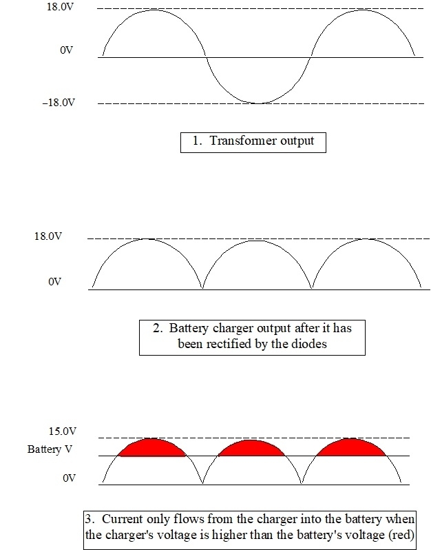
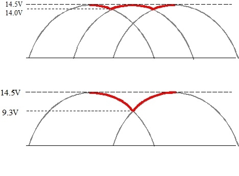
To do justice to this explanation, it's easier to start with battery chargers. Here again, if you don't follow this, or if it becomes too tedious or confusing, we'll still get through this. Alternating current in your house wiring changes direction back and forth 60 times per second, (60 cycles per second, or 60 hertz). Even this will become important later. When graphed, the waveform looks like the first one in the first image below. After it passes through a transformer, we get the same waveform, but a lower voltage version. Plus and minus 18.0 volts is shown. That would be typical for a larger wheel-type charger set to a medium charge rate. Diodes in the charger redirect current during the negative half of the cycle to positive current flow. The waveform, and current flow, look like the second waveform. Output voltage, (pressure), goes from 0 volts to 18 volts in this example.

A good, but fully-discharged battery will measure close to 12.2 volts. At any time the voltage coming out of the charger is less than 12.2 volts, no current will flow. Think of a piston-type water pump pushing water into a storage tank. No water will flow into the tank until the pump's pressure pulses higher than the pressure in the tank. This means current flowing into the battery pulses on and off 120 times per second. That pulsing physically causes the plates in the battery to vibrate.

The lead in batteries flakes off the plates over time. This can't be avoided, and battery manufacturers know how quickly this will happen. They offer warranties to capitalize on that, and make them as long as possible. That lead flaking occurs faster and faster as the battery gets older. When the battery charger makes them vibrate, the flaking speeds up. That material builds up in the bottom of the case. When it builds high enough, it shorts the plates in that cell, then the battery must be replaced.

When charging at a high charger setting, the voltage in the second waveform might go to 20.0 volts instead of 18.0 volts. During the times current flows, (waveform 3), it pulses harder and vibrates the plates a lot harder. That greatly increases how much lead flakes off. This is why we always recommend charging at the slowest rate the charger offers, especially with older batteries. Two hours is usually sufficient to reach near a full charge.

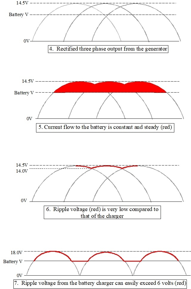
The second image shows generator output. Waveform # 4 shows the three-phase output, already rectified. Where the voltage from the battery charger goes from 0.0 volts to some maximum, here the voltage never goes to 0.0 volts, or even below battery voltage. There is always one phase contributing some current, and two are contributing at times. That's shown with the red area at the top of the fifth waveform.

We're finally coming to that third method of AC generator failure. Since the three output voltages are rising and falling, and they're overlapping, the voltage leaving the output stud looks like the red line at the top of the sixth waveform. This is called, "ripple voltage". By comparison, ripple voltage from the battery charger is shown in the seventh waveform. To be accurate, it would actually be 18.0 volts, but the battery itself is limiting how low the voltage will go.

We can measure ripple voltage, but not accurately. When you measure charging voltage with the engine running, that is done on the "DC Volts" scale on the meter, and the battery disregards ripple voltage by smoothing and averaging out system voltage. On the "AC Volts" scale, the meter measures the change in voltage over a short period of time and disregards, or blocks out, any DC voltage. In the sixth waveform, ripple voltage is 0.5 volts, (14.5 †14.0 volts).

The voltmeter is what prevents us from measuring ripple voltage accurately. There's at least a dozen individual coils of wire around the stationary stator assembly. Each one gets some voltage induced into it as the north †south magnetic fields from the field coil rotates past them. That creates at least 24 voltage pulses per revolution. Multiply that by three phases, then there's 72 pulses per revolution. Next, the crankshaft pulley is roughly six times larger in circumference than the pulley on the generator. The generator spins six times faster than engine speed, so now there's at least 432 voltage pulses per crankshaft revolution. Engines typically idle at around 800 rpm, or 13 revolutions per second. That means ripple voltage will be at a frequency of almost 5,616 hertz.

Voltmeters can only be accurate at one frequency on the "AC Volts" scale. They are designed to be accurate at 60 hertz which is found in home wiring. At any other frequency, the meter will reduce how well it responds. It may see a voltage to measure, but the value will drop off as the frequency gets further from 60 hertz. AC voltmeters used by the military can be accurate up to 400 hertz, but even those can't measure ripple voltage accurately.

When it comes to the professional charging system tests, the testers want us to put the generators at a speed where they're most efficient. That's at 2,000 rpm. Automatic testers know when that is reached by measuring the ripple voltage frequency. It will be near 14,256 hertz now. There are a few tester models that are designed to be accurate around that frequency. They can measure ripple voltage as an actual voltage and include that on a paper printout. Most testers just display ripple voltage on a relative bar chart with six or seven LED lights. The number of lights lit up or flickering indicates whether ripple voltage is "high" or "low". No exact voltage is given.

Enough suspense. The third method of operation with AC generators is when there's a failure of one diode. One of the three phases is lost, as shown in the lower waveform in the third image. Ripple voltage here is 5.2 volts, (14.5 †9.3 volts), but it would simply show up as "high" on the tester.

The high ripple voltage verifies the other symptom of this failure. That is the maximum current the generator will be able to develop is exactly one third of its rated current. That's roughly 22 amps from your 65-amp unit. Up to three of those amps goes right back to run the field coil, so what you're left with is barely enough to run two headlights, the tail lights, ignition system, and an electric fuel pump. There's nothing left over to run the heater fan or to keep the battery charged. The battery has to make up any difference until it slowly runs down over days or weeks.

So a diode failure is the second type of failure for an AC generator after a total failure to charge, but there is a third failure method that only applies to this GM generator. Remember the story of how this generator can be used as a single-wire system for a hot rod? There still has to be a current source for the field coil and to run the built-in voltage regulator. That is done internally with a "diode trio". They tap off a tiny fraction of current from each of the three stator windings, rectify that through the very small diodes in the diode trio, and use that to supply the field coil, and it is used to go back out on your brown wire to turn off the "Battery" light.

A failure of one of the diodes in the diode trio is somewhat common. Very often owners don't notice the only clue, but mechanics do when they drive the vehicle into the shop for other services. That is the "Battery" light will be lit very dimly. When the phase currently producing current is the one with the bad diode in the diode trio, no current is supplied to the field coil, and no voltage is applied to the warning bulb. The bulb only turns on one third of the time, so it is dim. Current to the field coil drops out but the other two phases will still be contributing a little, so the electromagnetic field becomes weaker. That translates into less current being developed in the stator coil. The clue here, besides the dim light, is the maximum current that can be developed is less than the design value, but considerably more than the one third in the previous failure. You might be able to get as much as 45 to 50 amps under the full-load output current test.

There's one more observation, but you're unlikely to ever notice it. When building "bugged cars" for my students to diagnose, one was a failed diode in the diode trio that could be switched in or out. In the failed mode, charging voltage actually jumped up about 0.3 volts. That is due to how the voltage regulator responds. In this design, they see the momentary voltage dropout from the diode trio. The voltage regulator sees that and increases current flow through the field coil to make a stronger magnetic field. That causes higher voltage to be developed in the stator. Once the regulator sees the return of voltage from the diode trio, it takes longer to respond to that, so it keeps the field current at that higher value. Voltage regulators in other designs from other manufacturers can respond differently. They can cause output voltage to drop, even to the point of producing no output current.

Back in the 1970s through the '90s, it was common to repair these generators. Voltage regulators, diode trios, and worn brushes were common failures.

I have to stop here and point out we normally do not repair starters and generators today except for ourselves. For customer vehicles, we don't want to risk angering someone if the repair goes sour. It is also not a good value when we have to charge for the additional time. It's less expensive to just replace the assembly with one with a warranty. We can save money for ourselves by replacing just the defective parts when time isn't a consideration, but then we have only ourselves to blame if we have to do the job a second time.

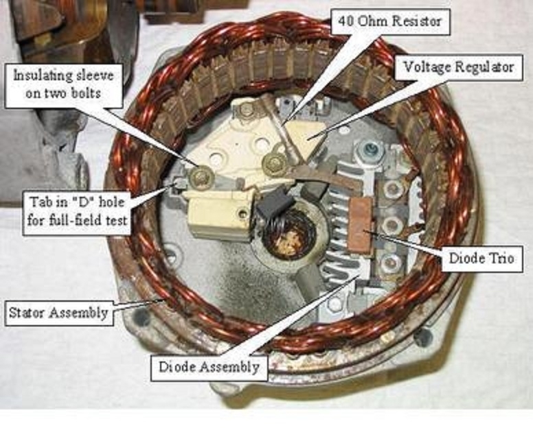
The fourth photo shows the inside of the rear half of the housing. Only half of the main diode block can be seen. They're between the three nuts and the finned aluminum heat sink. The other half is to the right, buried under the stator coil. Three tabs on the diode trio are attached under those three nuts too.

The two halves of this housing can be reassembled four ways by turning one part a quarter or half turn. It will work fine any of those four ways, but only three of them are legitimate. Which orientation the rear half is positioned to depends on the engine size and car model and year. When not rotated to the proper orientation, the rear mounting bolt hole will be in the wrong place, and the wires may not reach the two terminals, or they might not be accessible. All three versions are available at the auto parts stores. In the event the one you need is out of stock, either of the other two versions can be used, but the rear half must be turned to match that of the one you removed. Remove the four bolts, then spin the rear half, but do not pull it away from the front half as you do that. If you're repairing your generator, it is standard practice to mark both halves of the housing to know how to reassemble them in the right orientation.

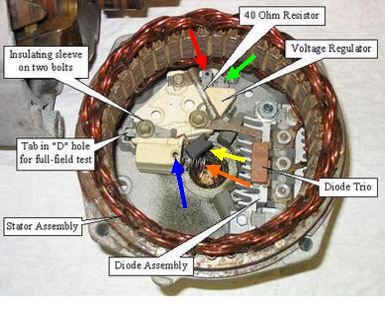
If you accidentally pull the rear half off, stop and refer to the fifth photo. There's two springs, (orange arrow), that get pushed into their tubes by two brushes, (yellow arrow). Those brushes are held on by short braided wires, so they won't fall out. Once both are pressed in all the way, stick a stretched-out paper clip or a toothpick through the hole, (blue arrow) to hold them in. A new voltage regulator comes with a new brush assembly. They will come with a thin wooden stick in that hole holding the brushes in. That stick or paper clip must stick out the hole right behind it in the housing. Once everything is fully reassembled, that stick is pulled out, then the spring-loaded brushes will snap into place. If you do that slowly, you'll hear the two clicks.

For fun, the red and green arrows are pointing to the two terminals you see on the outside.

Testing

When you measure the charging voltage at the battery, and it is between 13.75 and 14.75 volts, while that is good, it only means it is okay to perform the rest of the tests, but those full-load output current and ripple voltage tests require the professional load tester. When charging voltage is too low, there's one more test you can do yourself, and it's usually pretty easy. There's two different circuit designs for how voltage regulators are connected. Every charging system uses one of those designs. This is important in knowing how to do this test. It involves bypassing the voltage regulator. If the regulator is defective, bypassing it will cause the generator to charge wide-open. It's important to not raise engine speed above idle as doing so can make charging voltage go very high. That can destroy computers and burn out any light bulbs that are turned on. Do this bypass test just long enough to see the results, typically just a couple of seconds.

With Ford's regulator design, we have to apply 12 volts to one terminal to bypass it. That's easiest to do right at the regulator, on the inner fender. With Chrysler alternators, there are two wires plugged into it. The blue one is the 12-volt feed for the field coil and the remote-mounted external voltage regulator. The green wire at either location gets grounded to bypass the regulator. That's easiest to do right at the back of the alternator. Newer Fords in the '90s use the same circuit, but have a designated "test" terminal built in on the back of the generator. That also gets grounded.

Your GM generator has the same design Chrysler uses but they provided a test point. In the fourth photo, the "D" hole is pointed out on the left side. The tab is visible through that "D"-shaped hole on the rear housing. Don't worry if you can't see it. You just have to be able to reach it to stick something metal into the hole. A small screwdriver or pick works well. Stick it into the hole until it touches that tab, then move it to one side so it also touches the metal housing. That shorts out that point to bypass the voltage regulator, removing it momentarily from the circuit. Now the generator is "full-fielded" and will charge as hard as possible. If the regulator had been causing a no-charge condition, during this test you'll see system voltage rise noticeably, and / or the headlights will become brighter. You're also likely to hear the whine of the straining generator.

If you do not see voltage rise during the full-field test, chances are the voltage regulator is okay, and something else is causing the problem. For a no-charge condition, suspect worn brushes, especially on high-mileage vehicles. This almost always starts out as an intermittent problem that gets progressively worse over weeks and months. For low-charge conditions, suspect a failed diode. Those can be replaced in one block of three, but since they're snapped together, it's easier to replace the complete block of six. The regulator is already running the field coil as hard as possible to get output current up to where it needs to be, so bypassing it doesn't change anything.

The last failure is that diode trio. The dim "battery' light is the only clue and symptom. This is the least important failure and the repair often gets put off until other repairs are needed.

The question often arises about "upgrading" to a replacement generator with a higher output current. There are also kits available for modifying the generator you already have. All that's needed to get that higher current is to add a few inches of copper wire to the stator coils, and to replace the six diodes with those than can handle the higher current. When contemplating this modification, it's important to remember it doesn't matter what the generator is capable of. They all are just going to develop the amount of current that is needed, and no more. Similarly, a massive water pump can fill a municipal water tower in a few days, but once full, it will only pump as much water as needed to keep the tower full, and no more.

The only time any generator will produce its full rated maximum current is during the professional load test. With the correct size generator, the fuse link wire is large enough to handle that for more than the few seconds the test takes. It's when a larger generator is installed that this can lead to trouble. It works just the same as the original one, until that full-load test is performed. The larger unit's maximum current can exceed the rating of the fuse link wire and cause it to burn open. For those applications that use the larger generator, a larger fuse link will be used, as well as possibly larger wire for the rest of that circuit. Often you'll find three different fuse link sizes listed on diagrams for multiple different applications. Always replace one with another of the same gauge and insulation color.

That covers everything I can think of related to generator failures. You won't be tested on this, so just tell me what you find for voltages, then we'll figure out where to go next.
Was this
answer
helpful?
Yes
No
Monday, March 27th, 2023 AT 4:07 PM
Tiny
RD66
  • MEMBER
  • 61 POSTS
Hello again, I just want to say I really am thankful for your time and effort. There is a lot of really useful information you have provided. Just to let you know the flickering is still there, but I think I have narrowed it down to something going on at the switch. I replaced the switch a few months ago trying to solve this issue, but I found that the switch is broken. So, I put the other one I had purchased before back in and nothing has changed. However, I put some dielectric grease on the switch terminals before I plugged it back in. I ran the lights for about 20 minutes and no flickering but we will see what happens.
Was this
answer
helpful?
Yes
No
Monday, March 27th, 2023 AT 6:07 PM
Tiny
CARADIODOC
  • MECHANIC
  • 33,752 POSTS
Watch if it does it on low and / or high beams. When the circuit breaker internal to the switch is at fault, it will act up more often on high beams because they draw more current. Also watch if the flickering affects the dash lights or the brightness of the radio display.

A trick to finding this is to connect a test light to various points in the circuit to narrow down where it flickers and where it doesn't. Use a jumper wire if necessary so you can place the light where you can see it while driving. Based on the observations, I can suggest some of the best places to put the light.
Was this
answer
helpful?
Yes
No
Monday, March 27th, 2023 AT 6:20 PM
Tiny
RD66
  • MEMBER
  • 61 POSTS
I'm interested in hearing where you would put the light. Yes it only does it on high beam.
Was this
answer
helpful?
Yes
No
Monday, March 27th, 2023 AT 9:17 PM
Tiny
CARADIODOC
  • MECHANIC
  • 33,752 POSTS
If you have the option and you have a good idea of when the flickering will occur, you might consider unplugging one headlight bulb. If the flickering stops on high beam, the circuit breaker inside the headlight switch is the better suspect.

My first choice would be to put a jumper wire on the yellow wire in the headlight switch connector and hook that to the test light. Hang the test light out of the way, but where you can see it. Based on your observation the flickering doesn't affect the low beams, there is a chance the test light won't flicker on this wire, but we have to remember, this is a case where the amount of current flow might be an important variable. The bad connection can affect both circuits, but just show up on the high beams. This yellow wire splits the circuit in half. Whether or not the test light flickers here will tell us which way to go next.

If that yellow wire can be found in a connector at the base of the steering column, you can use that too as the place to hook the test light or the jumper wire to it.
Was this
answer
helpful?
Yes
No
Wednesday, March 29th, 2023 AT 6:22 PM
Tiny
RD66
  • MEMBER
  • 61 POSTS
It's interesting you bring up unplugging one headlight because I actually did that at one point when I was troubleshooting. While both lights were flickering I unplugged the passenger side bulb and the driver side stopped flickering. I'm assuming you want me to put that test light on the yellow wire while the lights are flickering to see if the test light also flickers?
Was this
answer
helpful?
Yes
No
Wednesday, March 29th, 2023 AT 11:36 PM
Tiny
CARADIODOC
  • MECHANIC
  • 33,752 POSTS
Yup, yellow wire, but you don't want to sit there and wait. Rather, place the test light where you can see it, then just drive the truck like normal. The test light will be on anytime the headlights are on, low or high beam. When the high beam flickering occurs, if the test light is also flickering, the cause has to be before the point where the test light is connected. That would include the circuit breaker inside the headlight switch.

If the test light does not flicker when the high beams do, the cause is after the point where the test light is connected. The better suspects would be the dimmer switch or one of its terminals. If it turns out it appears to be caused by the dimmer switch, you could use a jumper wire to connect the yellow wire to the light green wire at the dimmer switch connector. That will bypass the dimmer switch and its terminals. Leave the switch connected because a pair of high beam bulbs draw a total of around 10 amps. That's too much for a little jumper wire to handle on its own.

For the test light, the jumper wire I would use so I don't have to try to hold the light while I'm driving, is a small, light duty one. You can find a pack of 12 at Harbor Freight Tools for around $3.00. You'll get two each of blue, yellow, green, red, white, and black. If you wanted to jump the dimmer switch at the connector without it plugged in, they should have a set of larger jumper wires. I never use those so I don't know the cost. A small jumper wire should be okay as long as the switch is plugged in to share the load. Current would only flow through the jumper wire when the arcing in the switch occurs.

If all flickering stops when a jumper wire is connecting the yellow and light green wires together, the cause has to be in the switch or its terminals in the connector.

Verify where you connect the test light, then tell me what it does when the headlights flicker.
Was this
answer
helpful?
Yes
No
Thursday, March 30th, 2023 AT 3:34 PM

Please login or register to post a reply.

Sponsored links