Hi and thanks for using 2CarPros.com.
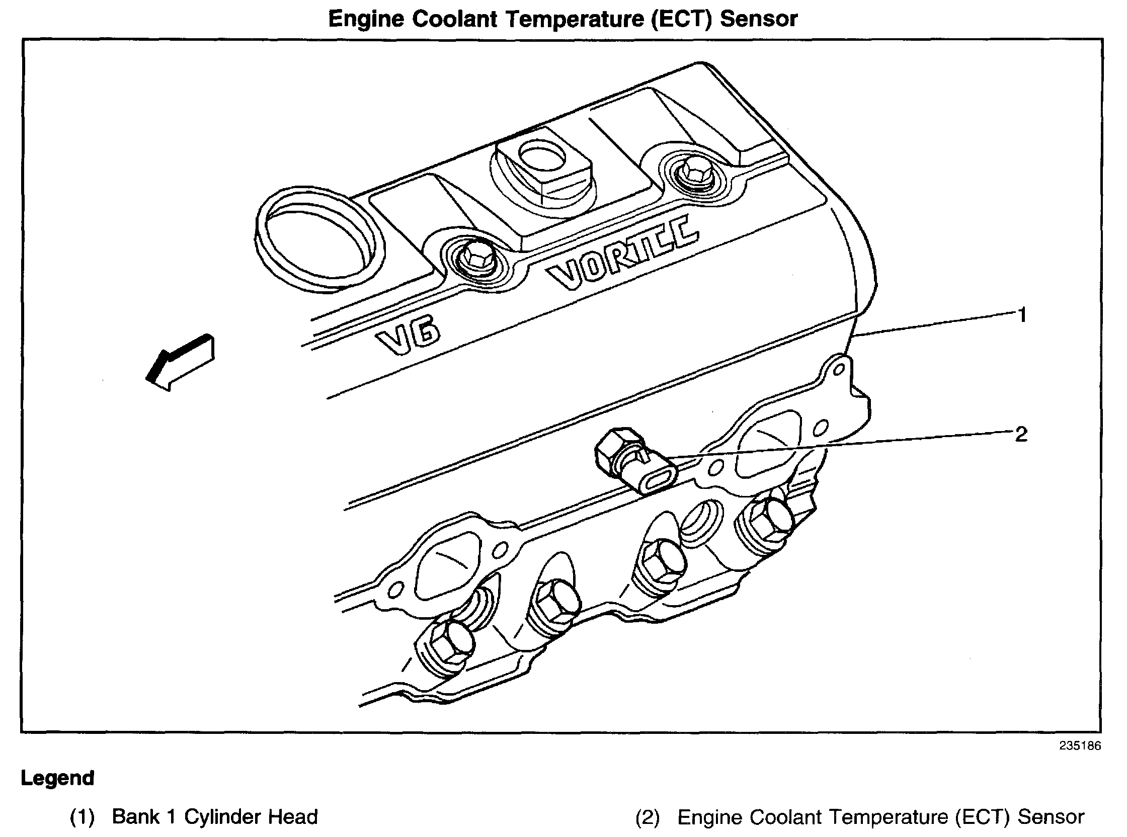
The first question I have is the fuel pressure. I realize it maintained 50+ but with the key on and engine off, it should be between 60 and 66 psi. Is that what you are getting? Next, is the electronic coolant temperature sensor (ECT). This sensor is not what sends a signal to the gauge in the vehicle, but rather it signals the computer what the coolant temperature is. Based on that information, the computer determines what the fuel mixture should be. I have attached a picture of its location (picture 1). The best way to determine if the ECT is an issue is using a live data scanner. With the engine cooled off, the sensor should indicate very close to the outside ambient temperature. Awhile back I had a GM van which had similar problems. The sensor said it was -40 degrees F when in actuality, it was 80 degrees F. The result was a very poorly running vehicle that was getting way too much gas to compensate for the cold temperatures.
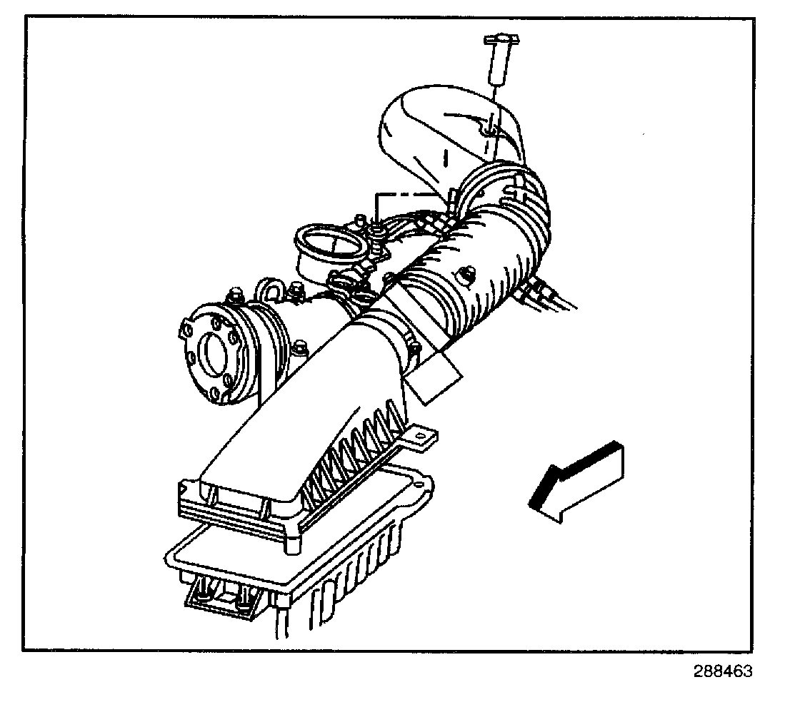
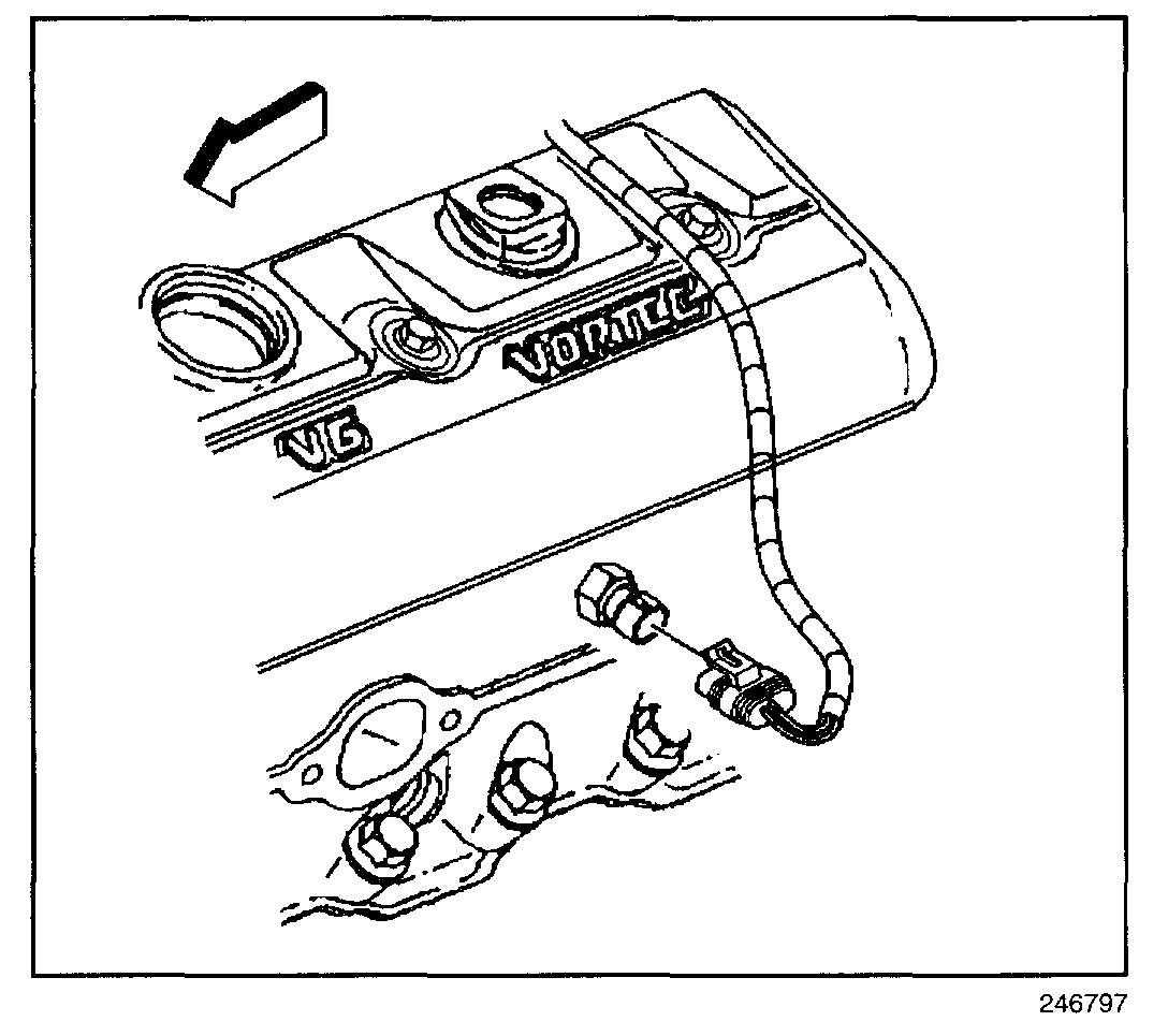
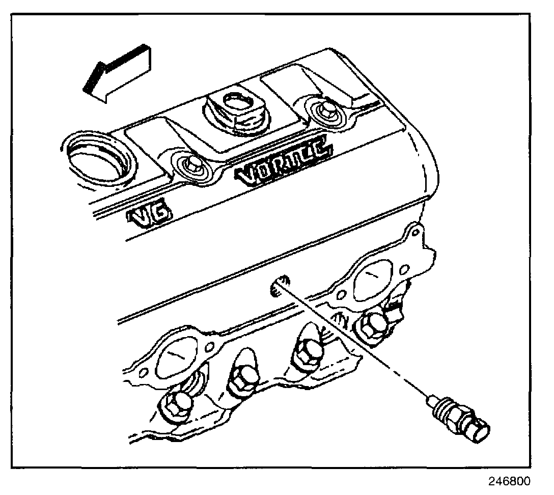
Here are the directions for replacing the ECT. Pictures 3,4,5 correlate with these directions. I realize you may not need them, but I added them just in case.
______________________________________________________
ECT SENSOR REPLACEMENT
REMOVAL PROCEDURE
NOTE: Use care when handling the coolant sensor. Damage to the coolant sensor will affect the operation of the fuel control system.
CAUTION: Refer to Battery Disconnect Caution in Service Precautions.
1. Disconnect the negative battery cable.
2. Loosen the wing nuts on the air cleaner cover and air cleaner outlet duct.
3. Move the air intake assembly aside.
CAUTION: Allow sufficient time for the engine to cool before removing the ECT sensor. A hot engine may cause an excessive coolant loss or a personal injury.
4. Relieve the coolant pressure.
5. Drain the cooling system below the level of the ECT sensor.
6. Disconnect the ECT sensor harness connector.
7. Remove the ECT sensor.
INSTALLATION PROCEDURE
1. Coat the threads (only) with GM P/N 12346004 sealer or equivalent.
NOTE: Refer to Component Tightening Notice in Service Precautions.
2. Install the ECT sensor in the engine.
Tighten
Tighten the sensor to 20 N.m (15 lb ft).
3. Connect the ECT sensor harness connector.
4. Refill the cooling system.
5. Install the air cleaner outlet duct assembly and tighten the wing nuts.
6. Connect the negative battery cable.
_____________________________________________________________
Now, if the fuel pressure is correct (and the pressure indicates no injector leaking), there are no vacuum leaks, and tuned it with all new components, the next thing I would consider checking is the crankshaft position sensor. Here is a definition of its function from alldata.
You will notice it discusses how the vehicle control module takes info from the sensor to determine a misfire and various other issues. At the end of the description, it indicates other codes which could be set. You mentioned there are other codes, but I'm not sure what they are, so I wanted to add this.
______________________________________________________________
The crankshaft position sensor provides the VCM with the crankshaft speed and the crankshaft position. The VCM utilizes this information in order to determine if an engine Misfire is present. The VCM monitors the CKP sensor for a momentary drop in the crankshaft speed in order to determine if a misfire is occurring. When the VCM detects a misfire, a DTC P0300 will set.
The VCM also monitors the CKP sensor signal circuit for malfunctions. The VCM monitors CKP signal and the High and Low resolution signals. The VCM calculates these signals in order to determine a ratio. When the VCM detects that the ratio is out of normal operating range, the VCM will set a DTC P0337 or a DTC P0338.
____________________________________________________________
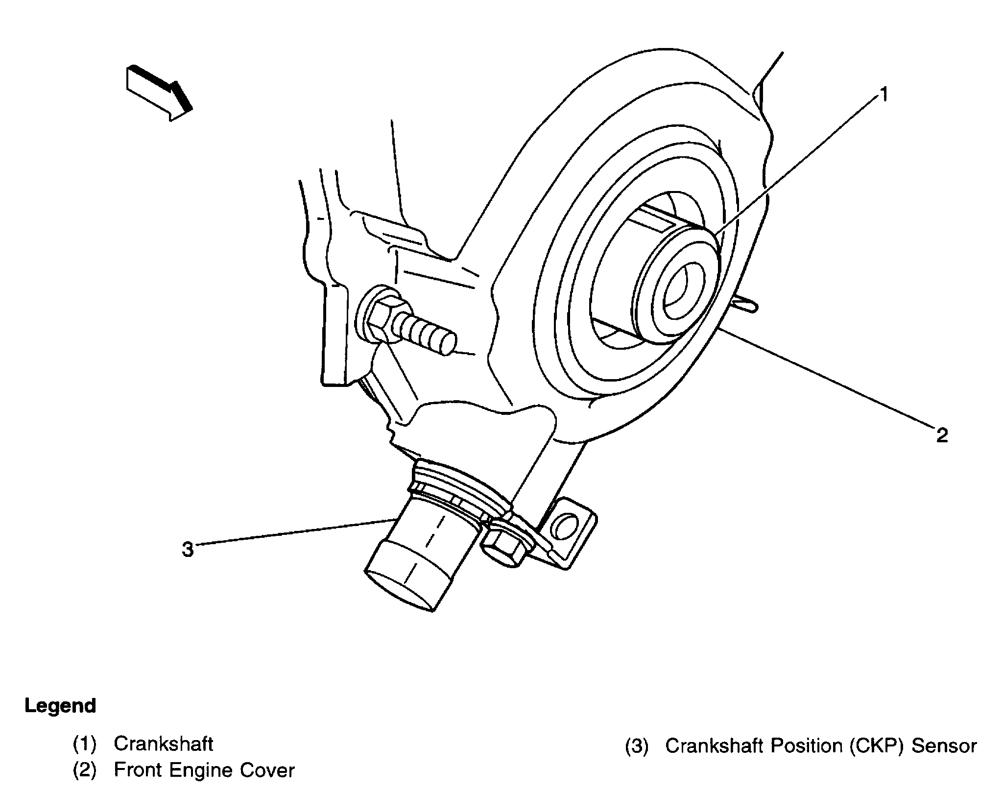
Okay, with that in mind, I need to explain something. If the crank sensor is an issue, it will not necessarily set a code indicating it is the problem. (pic 5 is of the crankshaft position sensor's location)
"Because a crankshaft position sensor is related to engine speed when they fail it may not trigger a CEL light. This is because there are some things that can stop the crankshaft position sensor's signal that will have nothing to do with the sensor going bad such as running out of gas or stalling the engine when letting the clutch pedal out to quickly..." (ken@2carpros).
Here is the link which discusses the sensor in more detail.
https://www.2carpros.com/articles/symptoms-of-a-bad-crankshaft-sensor
______________________________________________________________
Last, I would recommend checking engine compression. It does have some miles on it. Anything more than a 30% variation between the highest and lowest compression found can cause a bad idle and poor running conditions. Here are general directions for checking compression.
https://www.2carpros.com/articles/how-to-test-engine-compression
Here are directions specific to your vehicle from alldata.
______________________________________________________________
ENGINE COMPRESSION TEST
1. Disconnect the positive ignition coil wire plug from ignition coil.
2. Disconnect the fuel injector electrical connector.
3. Remove all the spark plugs.
4. Block the throttle plate wide open.
5. Charge the battery if the battery is not fully charged.
6. Start with the compression gauge at zero. Then crank the engine through four compression strokes (four puffs).
7. Make the compression check the same for each cylinder. Record the reading.
The minimum compression in any one cylinder should not be less than 70 percent of the highest cylinder. No cylinder should read less than 690 kPa (100 psi). For example, if the highest pressure in any one cylinder is 1035 kPa (150 psi), the lowest allowable pressure for any other cylinder would be 725 kPa (105 psi). (1035 x 70% = 725) (150 x 70% = 105).
8. If some cylinders have low compression, inject approximately 15 ml (one tablespoon) of engine oil into the combustion chamber through the spark plug hole.
^ Normal - Compression builds up quickly and evenly to the specified compression for each cylinder.
^ Piston Rings Leaking - Compression is low on the first stroke. Then compression builds up with the following strokes but does not reach normal. Compression improves considerably when you add oil.
^ Valves Leaking - Compression is low on the first stroke. Compression usually does not build up on the following strokes. Compression does not improve much when you add oil.
^ If two adjacent cylinders have lower than normal compression, and injecting oil into the cylinders does not increase the compression, the cause may be a head gasket leaking between the two cylinders.
9. Install the removed parts.
10. Connect the disconnected components.
No cylinder should be below 100 psi.
________________________________________________________
I hope this helps and doesn't make things worse. I will say that if everything checks out as good, I would suspect the spider injection system may be an issue. They were notorious for having issues. I was able to find one technical service bulletin (TSB) related to the fuel system and rough idle issues at start up. It's long, so I saved it for last. Starting with pic 6 through then end all correlate with this TSB and recommended service.
FUEL SYSTEM - MIL ON/ROUGH IDLE ON START-UP
Related Links
Cleaning Procedures
Central SFI to MFI Conversion Instructions
1. Loosen the fuel filler cap to relieve vapor pressure in the fuel tank.
2. Remove the Positive Crankcase Ventilation (PCV) clean air tube from the air inlet tube and set aside.
3. Remove the bonnet and inlet tube from the throttle body.
4. Remove the brake booster vacuum hose and connector from the intake manifold.
5. Remove the electrical connector from the CSFI fuel metering body.
6. Remove ignition wires 1, 3, 5, and 7 from the distributor cap.
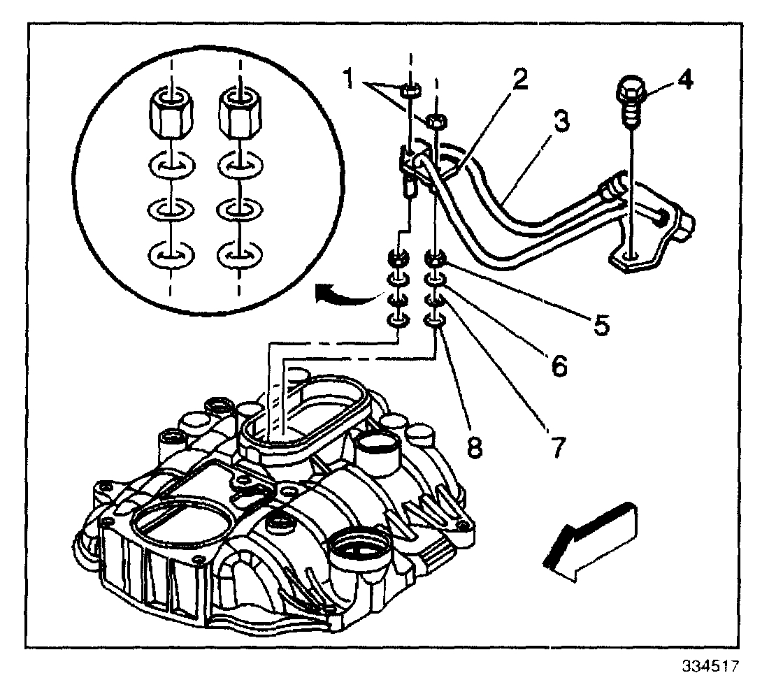
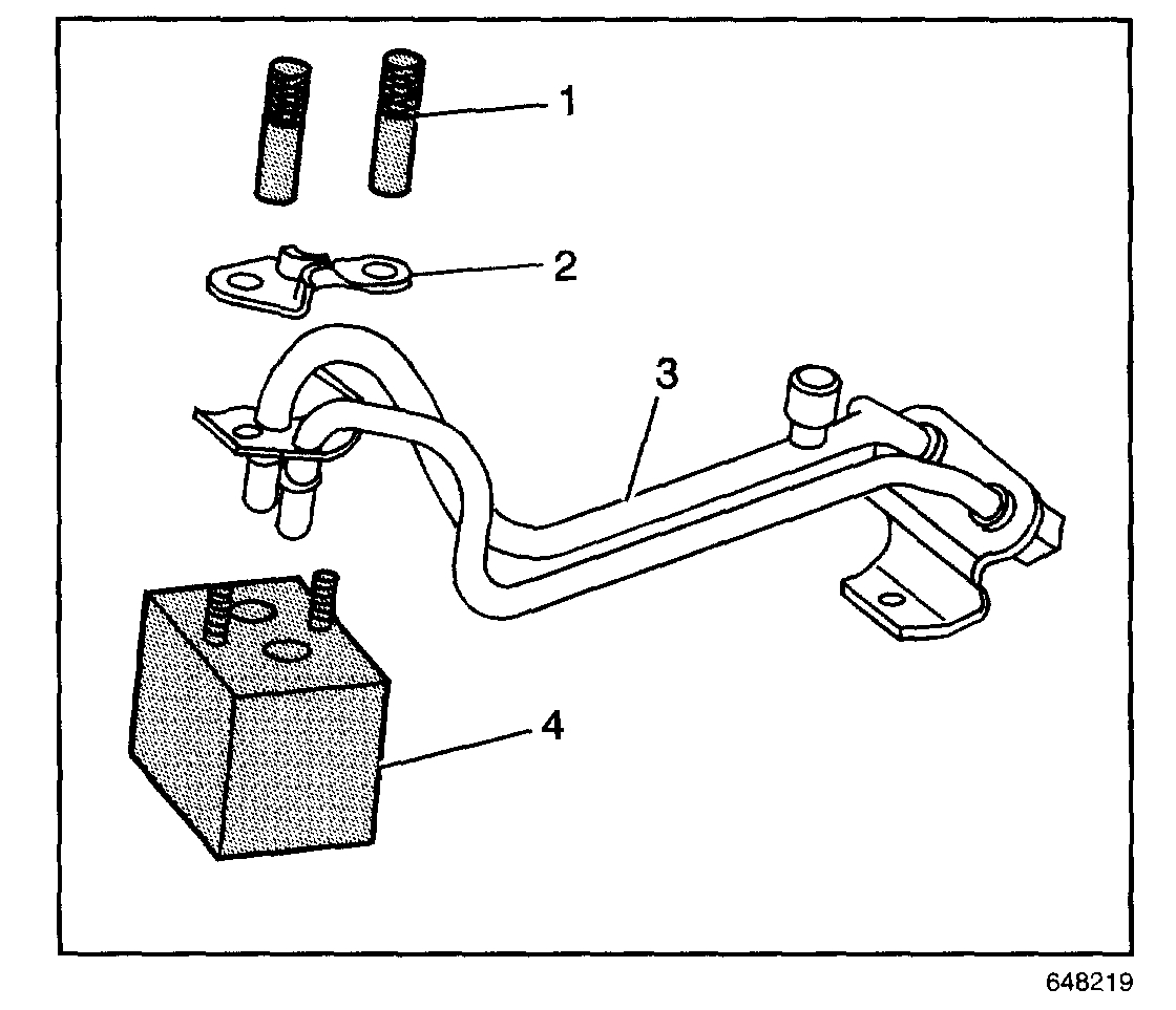
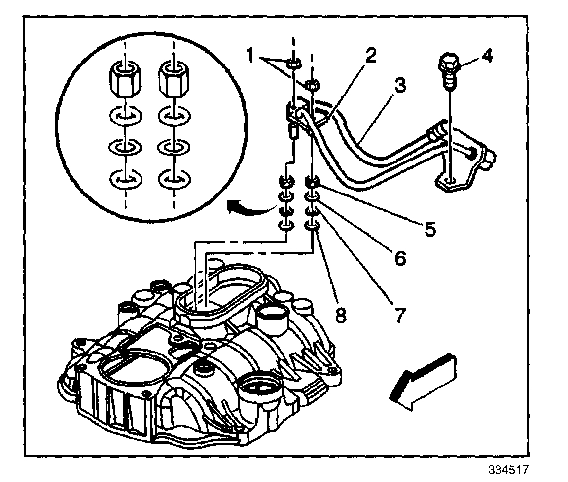
7. Remove the fuel line bolt (4) at the rear of the intake manifold.
8. Relieve the fuel system pressure at the service fitting on the fuel line. Use a shop towel to contain any fuel that may exit the service fitting.
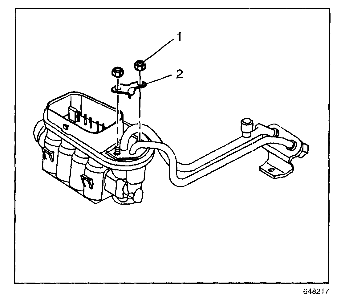
9. Remove the nuts (1) and clamp (2) from the fuel pipe.
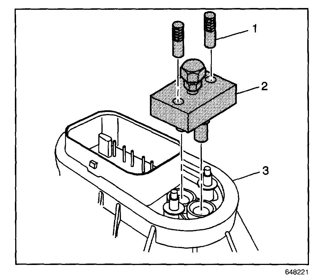
10. Remove the fuel pipes from the metering body. Be careful not to disturb the O-rings, washer, and spacer in the metering body.
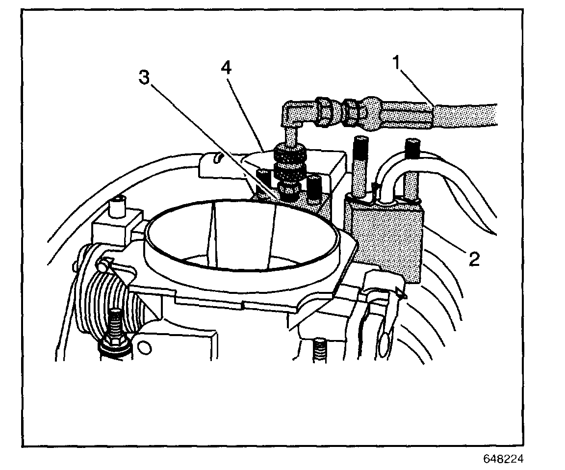
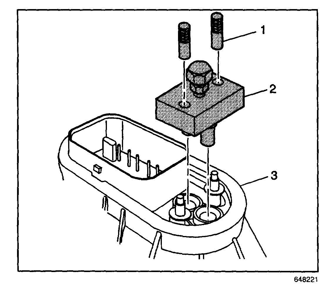
11. Install the J 44466-12 (2) and the J 44466-13 (1) to the metering body and tighten. Make sure that the fuel pipe 0-rings, washer, and spacers are present and in their proper position.
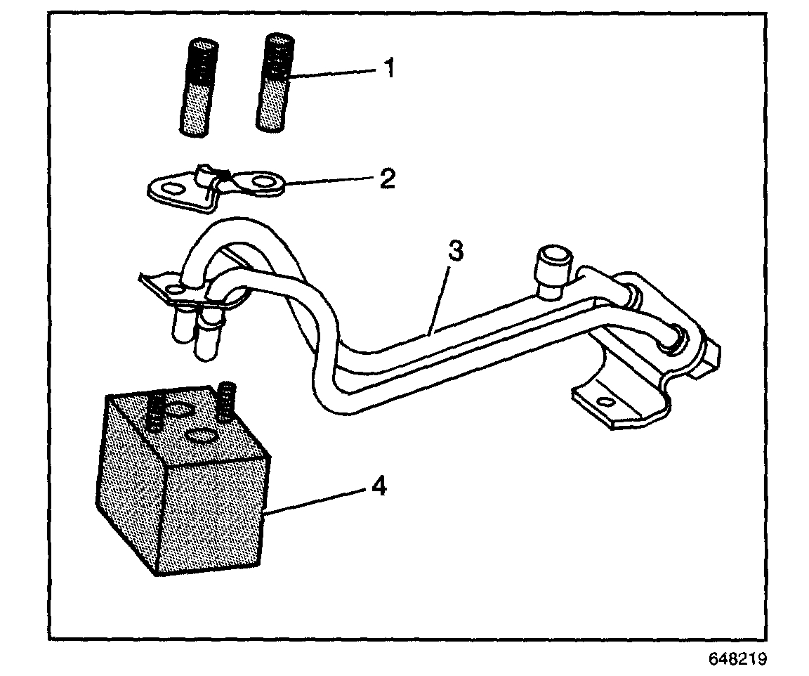
12. Install the J 44466-11 (4), clamp (2), and J 44466-13 (1) to the fuel pipe and tighten.
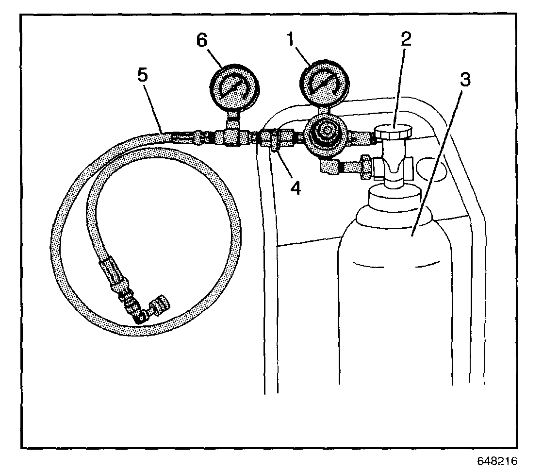
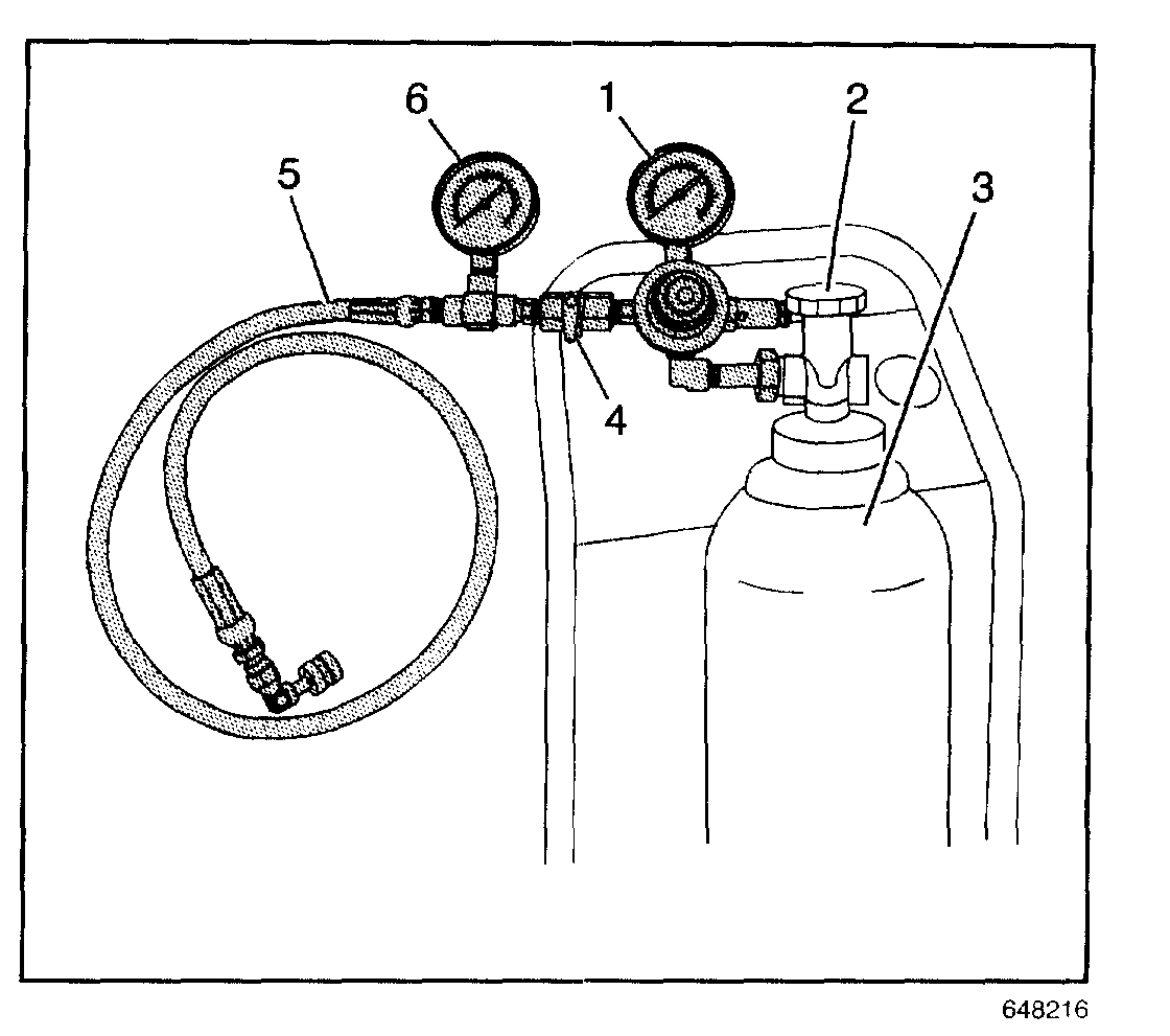
13. Obtain the J 41413, close the valve (2) on the tank, and remove the regulator assembly.
14. Install the J 44466-10 (5) to the J 41413 tank (3). The J 44466-10 regulator is preset to 150 psi.
15. Connect the J 44466-10 hose (1) to the J 44466-12 (3).
16. Install the J 39021 Injector/Coil Balance Tester, the J 39021-210 Injector Tester Adapter Box, and J 39021-301 V6 Fuel Injector Test Adapter (1) or J 39021-302 V8 Fuel Injector Test Adapter to the metering body electrical connector.
17. Adjust the amperage selector switch on J 39021 to 0.5 amps.
18. Open the valve (2) on the tank (3).
19. Open the valve (4) on the J 44466-10 to pressurize the fuel system. The minimum pressure required on the gauge (6) is 150 psi. If 150 psi is not obtained, the tank (3) must be refilled prior to performing this procedure.
20. Close the valve (4) on the J 44466-10.
21. Energize one injector using the J 39021. Observe a pressure drop on the gauge (6) and verity the injector/poppet valve operation. An injector/poppet that is "stuck" and not operational will have no pressure drop on the gauge. It an injector remains "stuck", repeat the procedure multiple times (as required) until the injector is operational.
22. Repeat Steps 19, 20 and 21 for each individual injector to verify that all injector/poppet valve assemblies are "unstuck" and functional.
23. Shut off pressure valve (2) on the tank (3) of the J 41413.
24. Bleed off the pressure at the J 44466-10.
25. Disconnect and remove the J 44466-10 (5) from the J 44466-12, and the J 41413.
26. Remove the J 39021-301 or J 39021-302, J 39021-210, and J 39021 from the metering body.
27. Install the vehicle electrical connector to the metering body.
28. Install the brake booster vacuum hose and connector to the intake manifold.
29. Install ignition wires 1, 3, 5, and 7 to the distributor cap.
30. Install the air inlet bonnet 10 the throttle body, tighten the wing-nut.
31. Install the PCV fresh air tube to the air inlet tube.
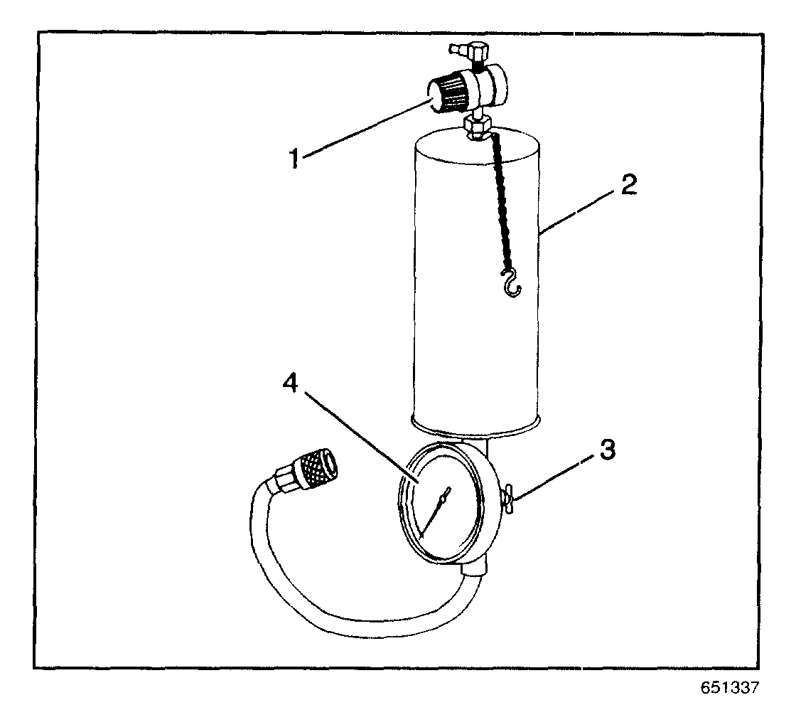
32. Obtain J 35800-A (2). Make sure the valve at the bottom of the canister (3) is closed.
33. Remove the canister top and add 24 ml (0.8 fl. oz.) Top Engine Cleaner, P/N 1050002 (Canada P/N 992872), to the canister.
34. Fill the remainder of the canister with regular unleaded gasoline and install the canister top.
35. Suspend J 35800-A from a convenient underhood location.
36. Connect the hose from J 35800-A to the service port on the J 44466-12
37. Open the valve (3) at the bottom of J 35800-A.
38. Connect a "shop air" source to the fitting at the top of J 35800-A and adjust the regulator (1) to 75 psi.
39. Start the vehicle. It may be necessary to re-adjust the J 35800-A pressure regulator to maintain 75 psi.
40. Let the vehicle run at idle until the canister is empty and the vehicle stalls.
41. Remove the shop air supply from J 35800-A.
42. Depressurize the J 35800-A.
43. Disconnect the J 35800-A hose from the J 44466-12.
44. Remove the PCV clean air tube from the air inlet tube and set aside.
45. Remove the bonnet from the throttle body, and set aside.
46. Remove ignition wires 1, 3, 5, and 7 from the distributor cap.
47. Remove the brake booster vacuum hose and connector from the intake manifold.
48. Bleed the residual pressure from the J 44466-12.
49. Remove J 44466-13 (1) and J 44466-12 (2) from the metering body.
50. Remove J 44466-13 (1), clamp (2), and J 44466-11 (4), from the fuel pipe (3).
51. Install the fuel pipe (3) to the metering body. Make sure that all of the 0-rings (6 and 8), washers (7), and spacers (5) are present and in their proper position.
52. Install the clamp (2) and nuts (1).
Tighten
Tighten the nuts to 3 N.m (27 lb in).
53. Apply threadlock, P/N 12345382, or equivalent to the threads of the fuel pipe bolt (4). Install the bolt.
Tighten
Tighten the fuel pipe bolt to 6 N.m (53 lb in).
54. Install the brake booster vacuum hose and connector to the intake manifold.
55. Install the bonnet and air inlet tube to the throttle body.
56. Install the PCV fresh air tube to the inlet duct.
57. Install ignition wires 1, 3, 5 (7) to the distributor cap.
58. Add one (1) ounce of Port Fuel Injector Cleaner, P/N 12345104 (Canada P/N 10953467), to the vehicle fuel tank for each gallon of gasoline estimated to be in the tank. Instruct the customer to add the remainder of the bottle of Port Fuel Injector Cleaner to the vehicle fuel tank at the next fill-up. Further recommend that Port Fuel Injector Cleaner be added to the fuel tank every 3000 miles (4800 km) particularly if the vehicle is not started and driven every day. Inform the customer that the Port Fuel Injector Cleaner is not to be used at every fill up but may be reapplied every 3000 miles (4800 km).
59. Tighten the fuel tank filler cap.
60. Start the vehicle and check for fuel leaks.
61. Using the Tech 2(R) scan tool, check for any stored Powertrain DTC codes. Clear codes as required.
62. Disconnect the Tech 2(R) Scan tool.
63. Advise the customer to change brands of fuel.
There are a lot of steps, but I have a feeling it is fuel related / injector related.
I hope you find something helpful in this post. Please feel free to ask more questions or let me know if you need additional information.
Take care,
Joe
Images (Click to enlarge)
Jul 29, 2018 at 7:58 PM