Hi,
I would replace the rotor if it is moving. Also, disconnecting the exhaust won't hurt anything for testing. However, I'm leaning towards your thoughts as far as how would it be plugged one minute and not the next.
If you decide to put the chain on, here are the directions. The attached pics correlate with the directions.
__________________________________________
1993 Toyota Truck Pickup 2WD L4-144.4 2366cc 2.4L SOHC (22R-E)
Procedures
Vehicle Engine, Cooling and Exhaust Engine Timing Components Timing Chain Service and Repair Procedures
PROCEDURES
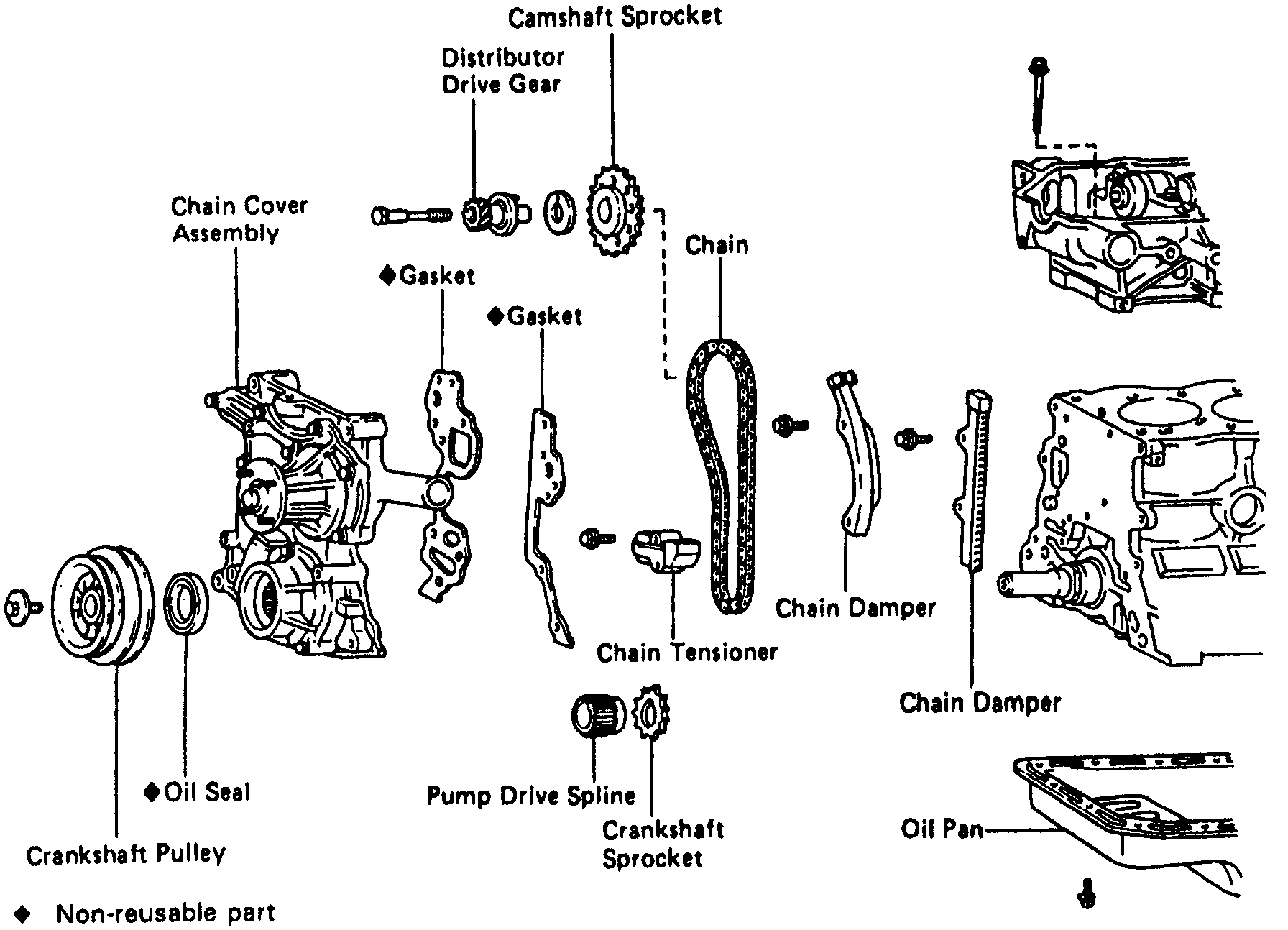
pic 1
PREPARATION FOR REMOVAL OF TIMING CHAIN
1. REMOVE CYLINDER HEAD
2. REMOVE RADIATOR
3. 4WD: REMOVE FRONT DIFFERENTIAL
4. REMOVE OIL PAN
(a) Remove the engine undercover.
(b) Remove the engine mounting bolts.
(c) 2WD: Place a jack under the transmission and raise the engine approx. 25 mm (0.98 in.)
(d) Remove the 16 bolts and 2 nuts.
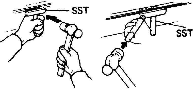
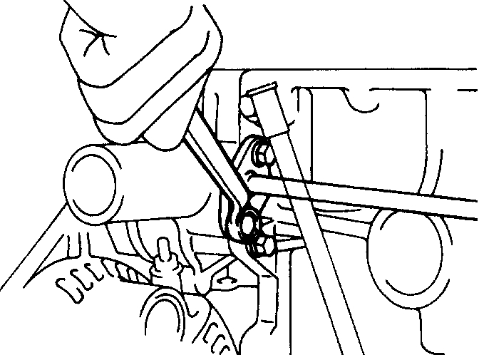
Pic 2
(e) Using SST and brass bar, separate the oil pan from the cylinder block.
SST 09032-00100
HINT: When removing the oil pan, be careful not to damage the oil pan flange.
TIMING CHAIN REMOVAL
1. With PS: REMOVE PS BELT
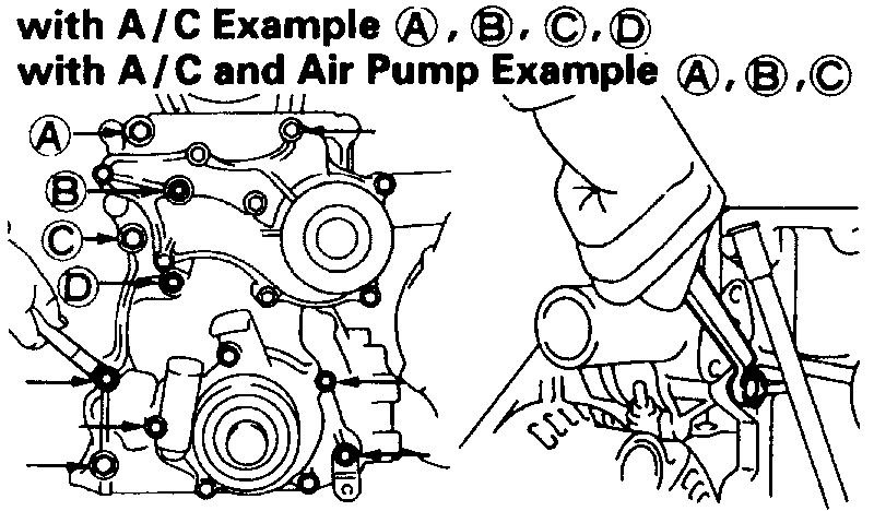
2. With A/C: REMOVE A/C BELT, COMPRESSOR AND BRACKET
pic 3
3. REMOVE FLUID COUPLING WITH FAN AND WATER PUMP PULLEY
(a) Loosen the water pump pulley set bolts.
(b) Loosen the belt adjusting bolt and pivot bolt of the generator, and remove the drive belt.
(c) Remove the set nuts, fluid coupling with fan and water pump pulley.
4. REMOVE CRANKSHAFT PULLEY
(a) with A/C (without Air pump) or with PS (with Air pump): Remove the No.2 crankshaft pulley.
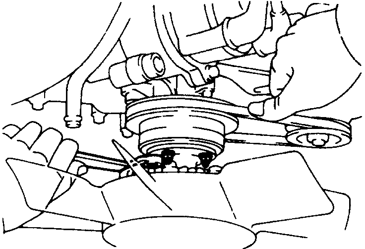
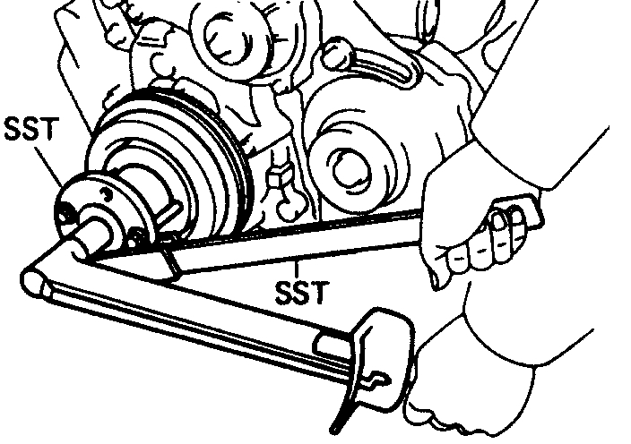
Pic 4
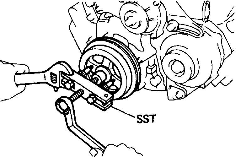
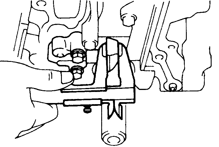
(b) Using SST to hold the crankshaft pulley, loosen the pulley bolt.
SST 09213-70010,09330-00021
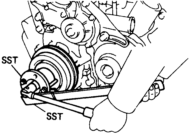
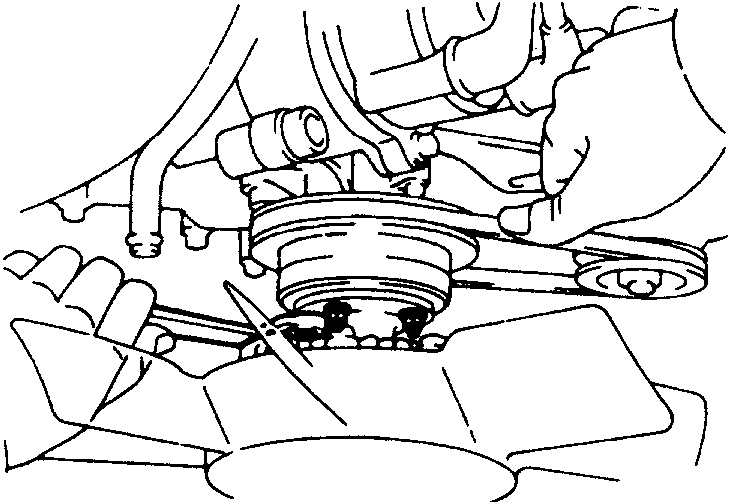
pic 5
(c) Using SST, remove the crankshaft pulley.
SST 09950-50010
pic 6
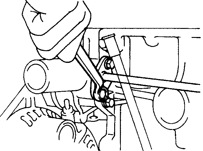
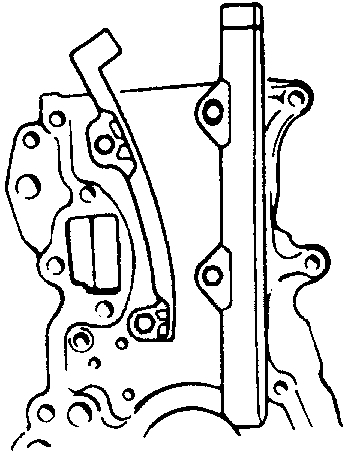
5. REMOVE NO.1 WATER BYPASS PIPE
Remove the 2 bolts and pipe.
Pic 7
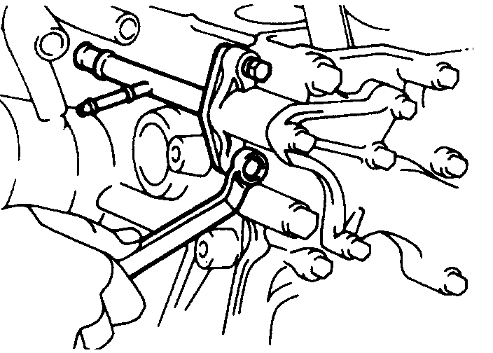
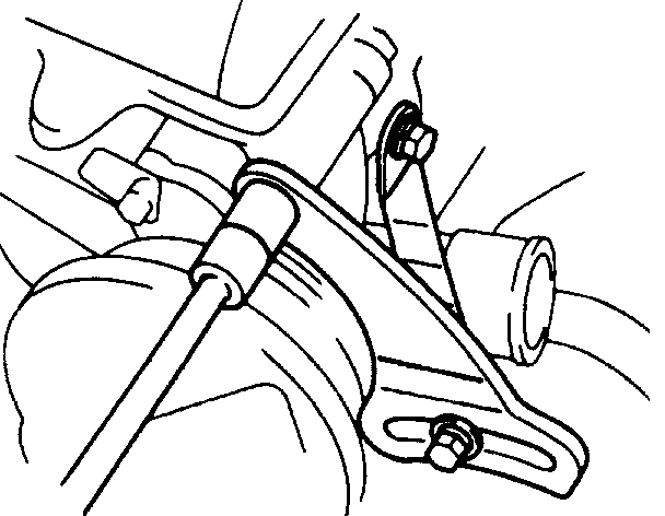
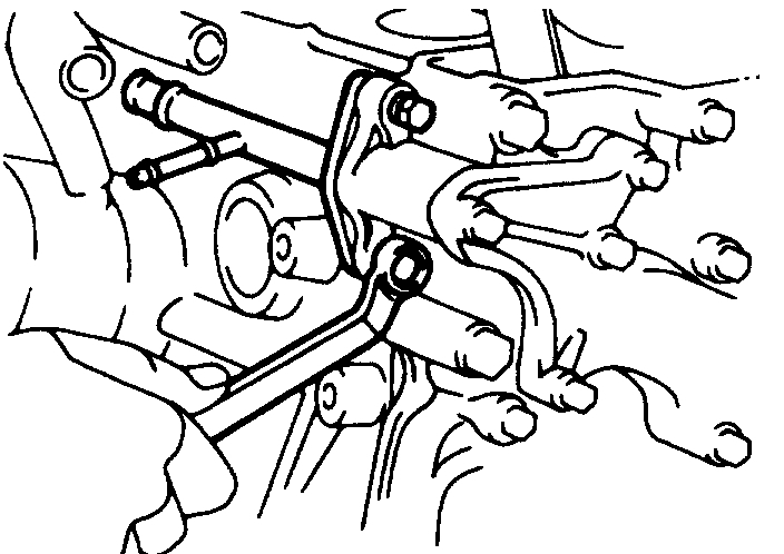
6. REMOVE FAN BELT ADJUSTING BAR
(a) With PS: Remove the bolt and PS lower bracket.
(b) Remove the 3 bolts and bar.
Pic 8
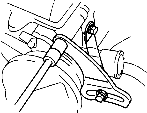
7. DISCONNECT HEATER WATER OUTLET PIPE
Remove the 2 bolts, and disconnect heater water outlet pipe.
Pic 9
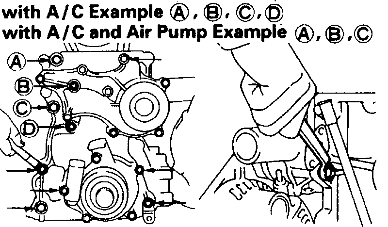
8. REMOVE CHAIN COVER ASSEMBLY
(a) Remove timing chain cover bolts shown by the arrows.
(b) Using a plastic faced hammer, loosen the chain cover and remove it.
Pic 10
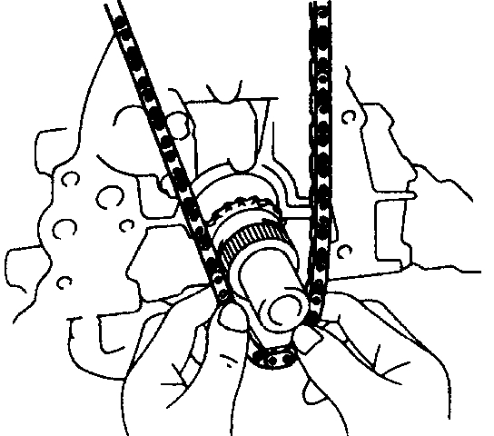
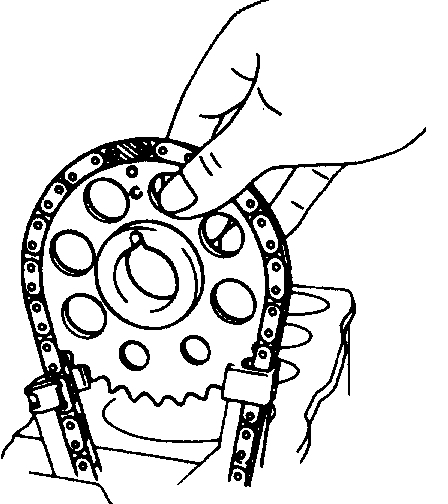
9. REMOVE CHAIN AND CAMSHAFT SPROCKET
(a) Remove the chain from the damper.
(b) Remove the cam sprocket and chain together.
Pic 11
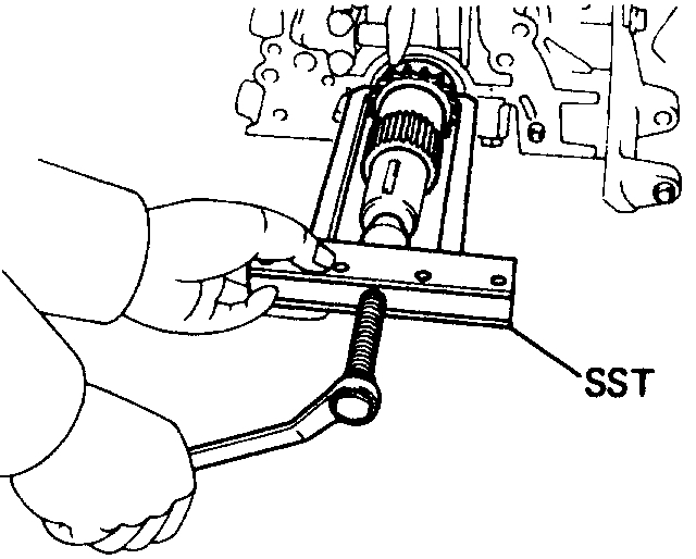
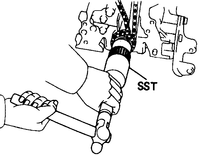
10. REMOVE PUMP DRIVE SPLINE AND CRANKSHAFT SPROCKET
If the oil pump drive spline and sprocket cannot be removed by hand. Use SST to remove them together.
SST 09950-40010
11. REMOVE GASKET MATERIAL ON CYLINDER BLOCK
COMPONENTS INSPECTION
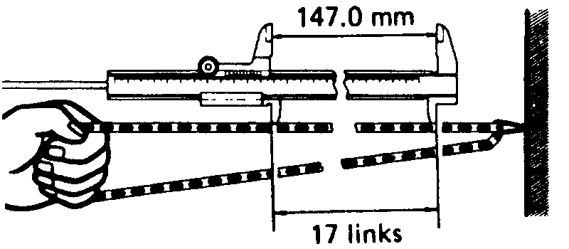
1. MEASURE CHAIN AND SPROCKET WEAR
pic 12
(a) Measure the length of 17 links with the chain fully stretched.
(b) Make the same measurements at least 3 other places selected at random.
Chain elongation limit at 17 links: 147.0 mm (5.787 in.)
If over the limit at any one place, replace the chain.
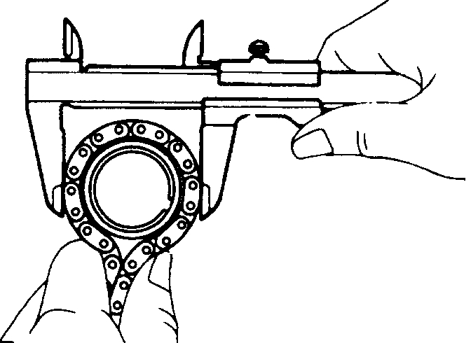
Pic 13
(c) Wrap the chain around the sprocket.
(d) Using a caliper gauge, measure the outer sides of the chain rollers as shown. Measure both sprockets.
Minimum crankshaft sprocket: 59.4 mm (2.339 in.)
Minimum crankshaft sprocket: 113.8 mm (4.480 in.)
If the measurement is less than minimum, replace the chain and 2 sprockets.
Pic 14
2. MEASURE CHAIN TENSIONER
Using a caliper gauge, measure the tensioner as shown.
Minimum tensioner: 11.0 mm (0.433 in.)
If the tensioner is worn or less than minimum, replace the chain tensioner.
Pic 15
3. MEASURE CHAIN DAMPERS
Using a micrometer, measure each damper.
Limit damper wear: 0.5 mm (0.020 in.)
If either damper is worn or less than minimum, replace the damper.
TIMING CHAIN INSTALLATION
pic 16
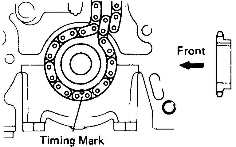
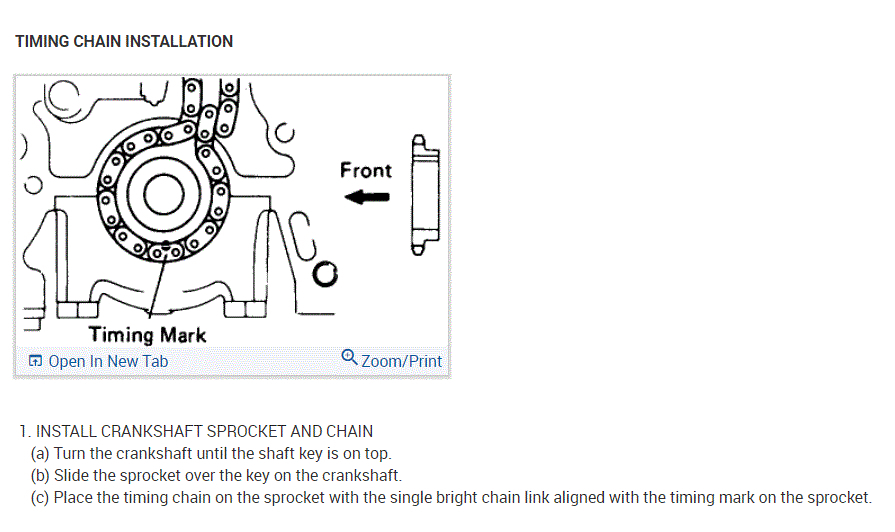
1. INSTALL CRANKSHAFT SPROCKET AND CHAIN
(a) Turn the crankshaft until the shaft key is on top.
(b) Slide the sprocket over the key on the crankshaft.
(c) Place the timing chain on the sprocket with the single bright chain link aligned with the timing mark on the sprocket.
Pic 17
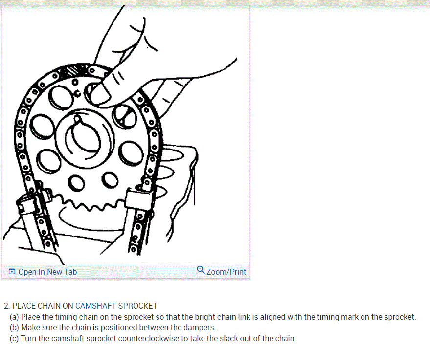
2. PLACE CHAIN ON CAMSHAFT SPROCKET
(a) Place the timing chain on the sprocket so that the bright chain link is aligned with the timing mark on the sprocket.
(b) Make sure the chain is positioned between the dampers.
(c) Turn the camshaft sprocket counterclockwise to take the slack out of the chain.
Pic 18
3. INSTALL OIL PUMP DRIVE SPLINE
Slide the oil pump drive spline over the crankshaft key.
HINT: If the oil pump drive spline is difficult to install by hand, install using SST.
SST 09608-35014 (09608-06040)
pic 19
4. INSTALL TIMING CHAIN COVER ASSEMBLY
(a) Remove the old cover gaskets. Clean the gasket surface. Install new gaskets over the dowels.
(b) Slide the cover assembly over the dowels and pump spline.
(c) Insert the bolts as shown and torque them.
Torque:
8 mm bolt: 13 N.M (130 kgf. Cm, 9 ft. Lbf)
10 mm bolt: 39 N.M (400 kgf. Cm. 29 ft. Lbf)
pic 20
5. INSTALL FAN BELT ADJUSTING BAR
(a) Temporarily install the adjusting bar to the alternator.
(b) Install the adjusting bar to the chain cover and cylinder head.
Torque: 13 N.M (130 kgf. Cm, 9 ft. Lbf)
pic 21
6. INSTALL HEATER WATER OUTLET PIPE
Connect the heater water outlet pipe to the timing chain cover with the 2 bolts.
Pic 22
7. INSTALL NO.1 WATER BYPASS PIPE
Install the pipe with the 2 bolts.
Pic 23
8. INSTALL CRANKSHAFT PULLEY
(a) Install the crankshaft pulley and bolt.
(b) Using SST to hole the crankshaft pulley, torque the bolt.
SST 09213-70010 and 09660-00021
Torque: 157 N.M (1.600 kgf. Cm, 116 ft. Lbf)
(c) with A/C: Install the No.2 crankshaft pulley.
Pic 24
9. INSTALL WATER PUMP PULLEY AND FLUID COUPLING WITH FAN
(a) Temporarily install the water pump pulley and fluid coupling withfan with the 4 nuts.
(b) Place the drive belt onto each pulley.
(c) Stretch the belt tight and tighten the 4 nuts.
10. ADJUST DRIVE BELT TENSION
11. With A/C: INSTALL A/C COMPRESSOR BRACKET, COMPRESSOR AND BELT
12. With PS: INSTALL PS BELT
13. INSTALL OIL PAN
(a) Remove any old packing material and be careful not to drop any oil on the contacting surfaces of the oil pan and cylinder block.
Using a razor blade and gasket scraper, remove all the packing (FIPG) material from the gasket surfaces.
Thoroughly clean all components to remove all the loose material.
Clean both sealing surfaces with a non-residue solvent.
NOTICE: Do not use a solvent which will affect the painted surfaces.
Pic 25
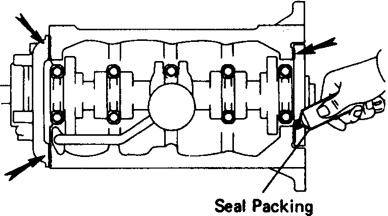
(b) Apply seal packing to the joint part of the cylinder block and chain cover, cylinder block and rear oil seal retainer.
Seal packing: Part No.08826 - 00080 or equivalent
pic 26
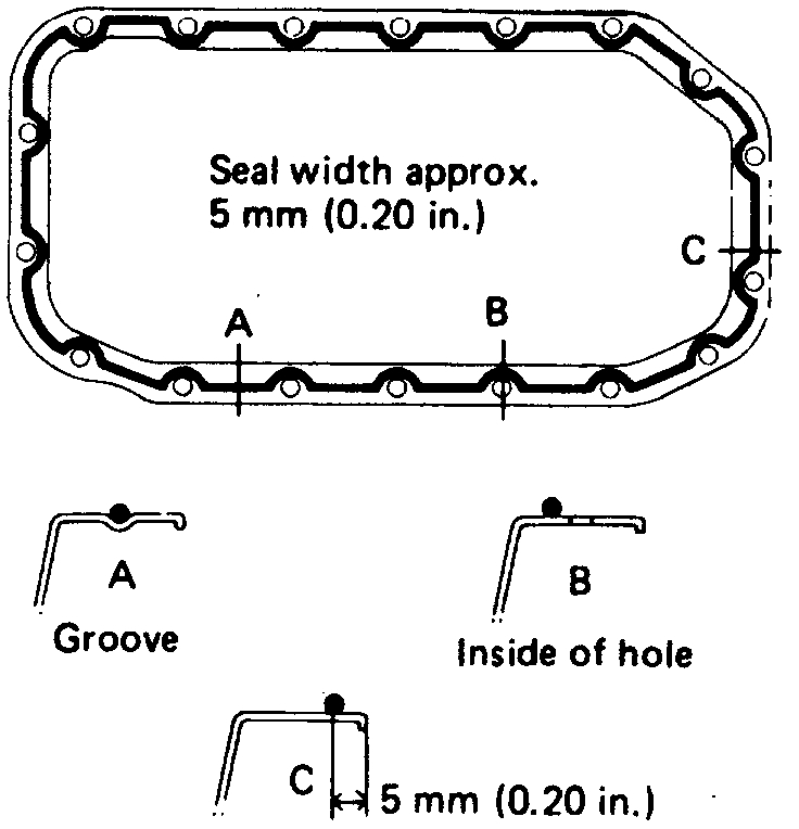
(c) Apply seal packing to the oil pan as shown in the illustration.
Seal packing: Part No.08826 - 00080 or equivalent
Install a nozzle that has been cut to a 5 mm (0.20 in.) Opening.
HINT: Avoid applying an excessive amount to the surface. Be especially careful near oil passages.
If parts are not assembled within 5 minutes of applying the seal packing, the effectiveness of the seal packing is lost and the seal packing must be removed and reapplied.
Immediately remove the nozzle from the tube and reinstall the cap after using the seal packing.
(d) Install the oil pan over the studs on the block with the 16 bolts and 2 nuts. Torque the bolts and nuts.
Torque: 13 N.M (130 kgf. Cm, 9 ft. Lbf)
(e) Lower the engine and install the engine mounting bolts.
(f) Install the engine under cover.
14. INSTALL RADIATOR
15. INSTALL CYLINDER HEAD
16. 4WD: INSTALL FRONT DIFFERENTIAL
___________________________________________________
Let me know if this helps.
Joe
Images (Click to make bigger)
Saturday, December 5th, 2020 AT 8:31 PM