Good afternoon,
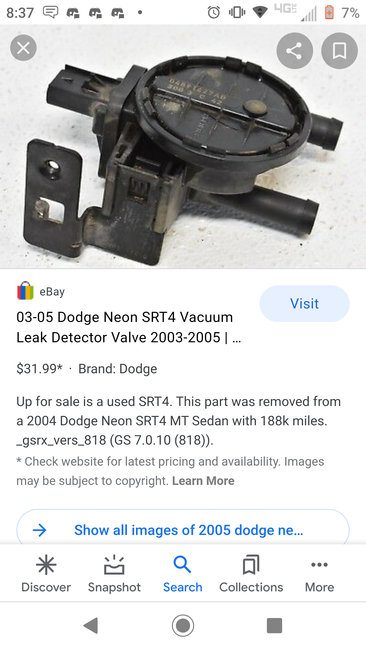
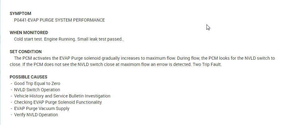
The leak detection pump is the part you posted. It has an electrical connection and 2 hoses.
There are 4 possible codes. The code number does not mean to replace the pump, it means it either has a voltage issue or a leak in the system. I need the code that you saw to hep narrow the reason for failure.
https://www.2carpros.com/articles/how-emission-control-systems-work
https://www.2carpros.com/articles/evap-system-code-repair
Roy
REMOVAL
1. Raise and support vehicle on a hoist.
2. Push locking tab on electrical connector to unlock and remove connector.
3. loosen the sway bar bracket to remove the pump bracket.
4. Remove pump and bracket as an assembly.
5. Disconnect lines from NVLD.
6. Remove filter.
7. Remove from bracket.
INSTALLATION
1. Install pump to bracket and tighten bolts to 1.2 N-m (10.6 in. lbs.).
2. Install filter and tighten to 2.8 N-m (25 in. lbs.).
NOTE: The LDP bracket must be between the rail and sway bar bracket.
3. Install pump and bracket assembly to body and tighten front bolt to 11.7 N-m (105 in. lbs.).
4. Install sway bar bracket bolt and tighten bolts to 33.8 N-m (25 ft. lbs.).
5. Before installing hoses to LDP, make sure they are not cracked or split. If a hose leaks, it will cause the Check Engine Lamp to illuminate. Connect lines to the LDP
6. Install electrical connector to pump and push locking tab to lock.
7. Lower vehicle
8. Use the DRB III scan tool, verify proper operation of LDP
OPERATION
The Natural Vacuum Leak Detection (NVLD) system is the next generation evaporative leak detection system that will first be used on vehicles equipped with the Next Generation Controller (NGC). This new system replaces the leak detection pump as the method of evaporative system leak detection. This is to detect a leak equivalent to a 0.020" (0.5 mm) hole. This system has the capability to detect holes of this size very dependably.
The basic leak detection theory employed with NVLD is the "Gas Law". This is to say that the pressure in a sealed vessel will change if the temperature of the gas in the vessel changes. The vessel will only see this effect if it is indeed sealed. Even small leaks will allow the pressure in the vessel to come to equilibrium with the ambient pressure. In addition to the detection of very small leaks, this system has the capability of detecting medium as well as large evaporative system leaks.
A vent valve seals the canister vent during engine off conditions. If the vapor system has a leak of less than the failure threshold, the evaporative system will be pulled into a vacuum, either due to the cool down from operating temperature or diurnal ambient temperature cycling. The diurnal effect is considered one of the primary contributors to the leak determination by this diagnostic. When the vacuum in the system exceeds about 1" H2O (0.25 KPA), a vacuum switch closes. The switch closure sends a signal to the NGC. The NGC, via appropriate logic strategies (described below), utilizes the switch signal, or lack thereof, to make a determination of whether a leak is present.
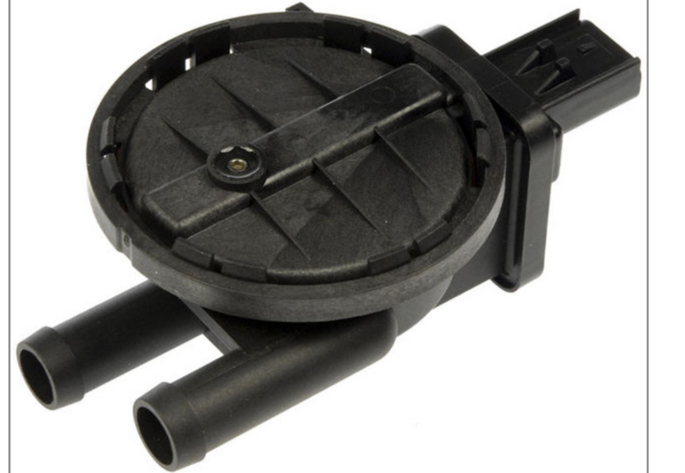
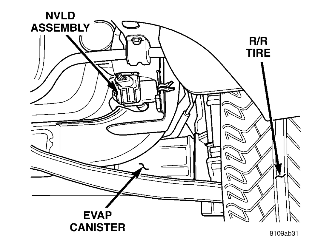
The NVLD device is designed with a normally open vacuum switch, a normally closed solenoid, and a seal, which is actuated by both the solenoid and a diaphragm. The NVLD is located on the atmospheric vent side of the canister. The NVLD assembly may be mounted on top of the canister outlet, or in-line between the canister and atmospheric vent filter. The normally open vacuum switch will close with about 1" H2O (0.25 KPA) vacuum in the evaporative system. The diaphragm actuates the switch. This is above the opening point of the fuel inlet check valve in the fill tube so cap off leaks can be detected. Submerged fill systems must have recirculation lines that do not have the in-line normally closed check valve that protects the system from failed nozzle liquid ingestion, in order to detect cap off conditions.
The normally closed valve in the NVLD is intended to maintain the seal on the evaporative system during the engine off condition. If vacuum in the evaporative system exceeds 3" to 6" H2O (0.75 to 1.5 KPA), the valve will be pulled off the seat, opening the seal. This will protect the system from excessive vacuum as well as allowing sufficient purge flow in the event that the solenoid was to become inoperative.
The solenoid actuates the valve to unseal the canister vent while the engine is running. It also will be used to close the vent during the medium and large leak tests and during the purge flow check. This solenoid requires initial 1.5 amps of current to pull the valve open but after 100 ms. will be duty cycled down to an average of about 150 mA for the remainder of the drive cycle.
Another feature in the device is a diaphragm that will open the seal in the NVLD with pressure in the evaporative system. The device will "blow off" at about 0.5" H2O (0.12 KPA) pressure to permit the venting of vapors during refueling. An added benefit to this is that it will also allow the tank to "breathe" during increasing temperatures, thus limiting the pressure in the tank to this low level. This is beneficial because the induced vacuum during a subsequent declining temperature will achieve the switch closed (pass threshold) sooner than if the tank had to decay from a built up pressure.
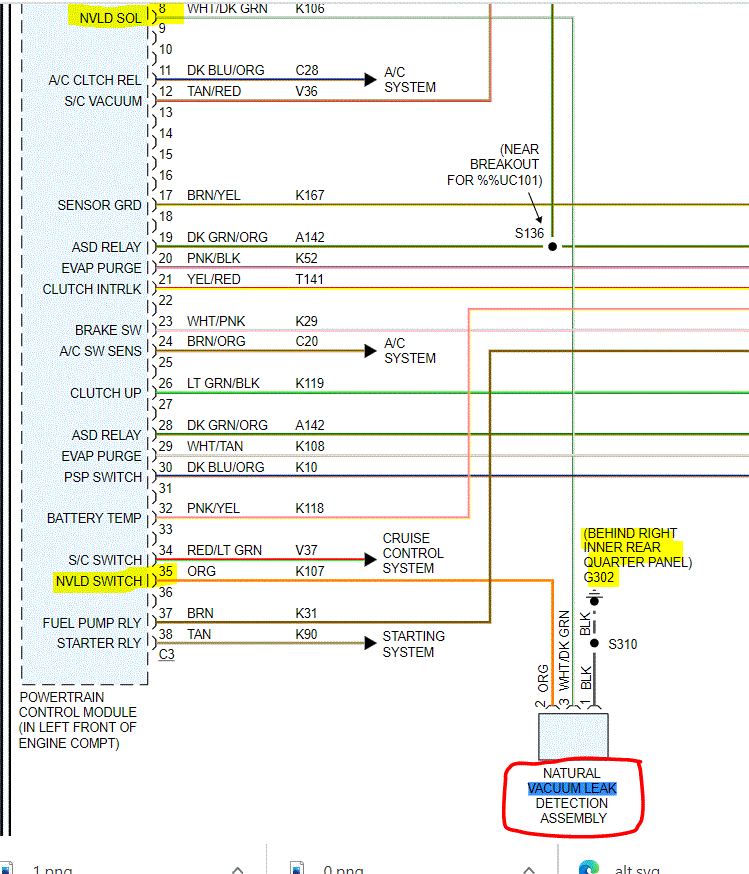
The device itself has 3 wires: Switch sense, solenoid driver and ground. The NGC utilizes a high-side driver to energize and duty-cycle the solenoid.
Mar 17, 2021 at 5:10 PM
(Merged)