Hi,
Based on what I heard and the number of miles, it may be a good idea. You will likely have to switch components between the two engines, but it should work as long as it is also a 5.4L. When I say switch components, I'm referring to sensors and electronics. The difference in the model year may make a difference as far as connectors and so on. Just take a few minutes and confirm that sensors and such exist in the same places.
If you decide to do this, here are the directions for the removal and replacement of the engine. The attached pics correlate with the directions.
_____________________________________
2001 Ford Truck F 150 4WD Pickup V8-5.4L SOHC VIN L
Removal
Vehicle Engine, Cooling and Exhaust Engine Service and Repair Procedures Engine Removal
REMOVAL
pic 1
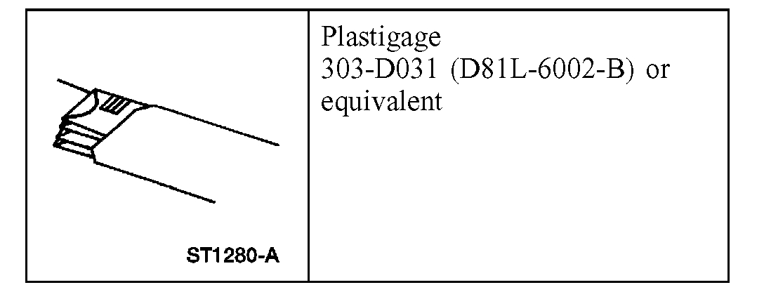
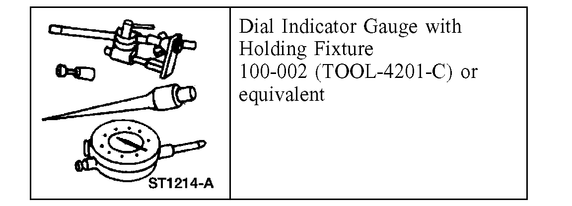
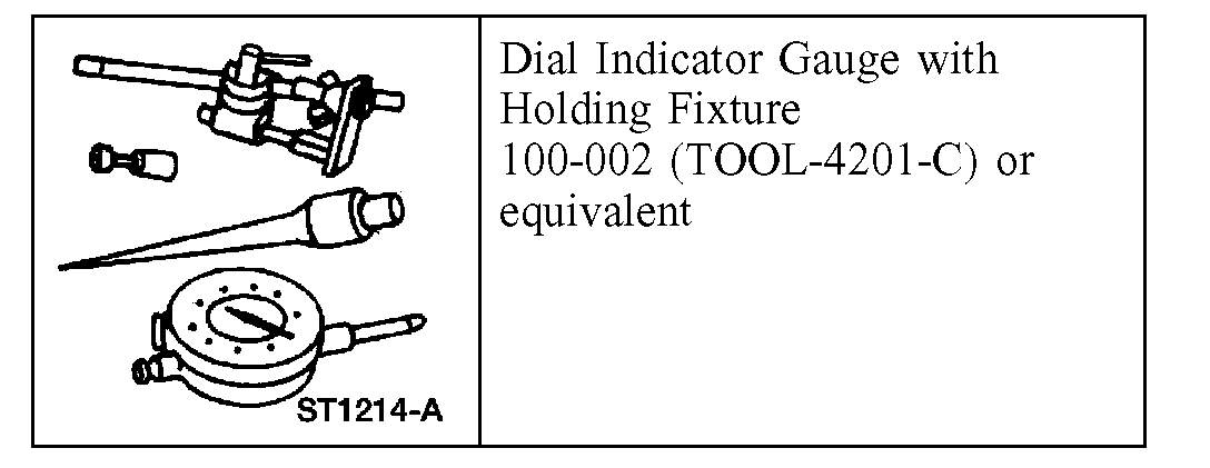
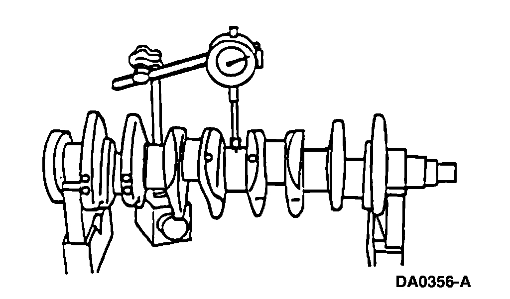
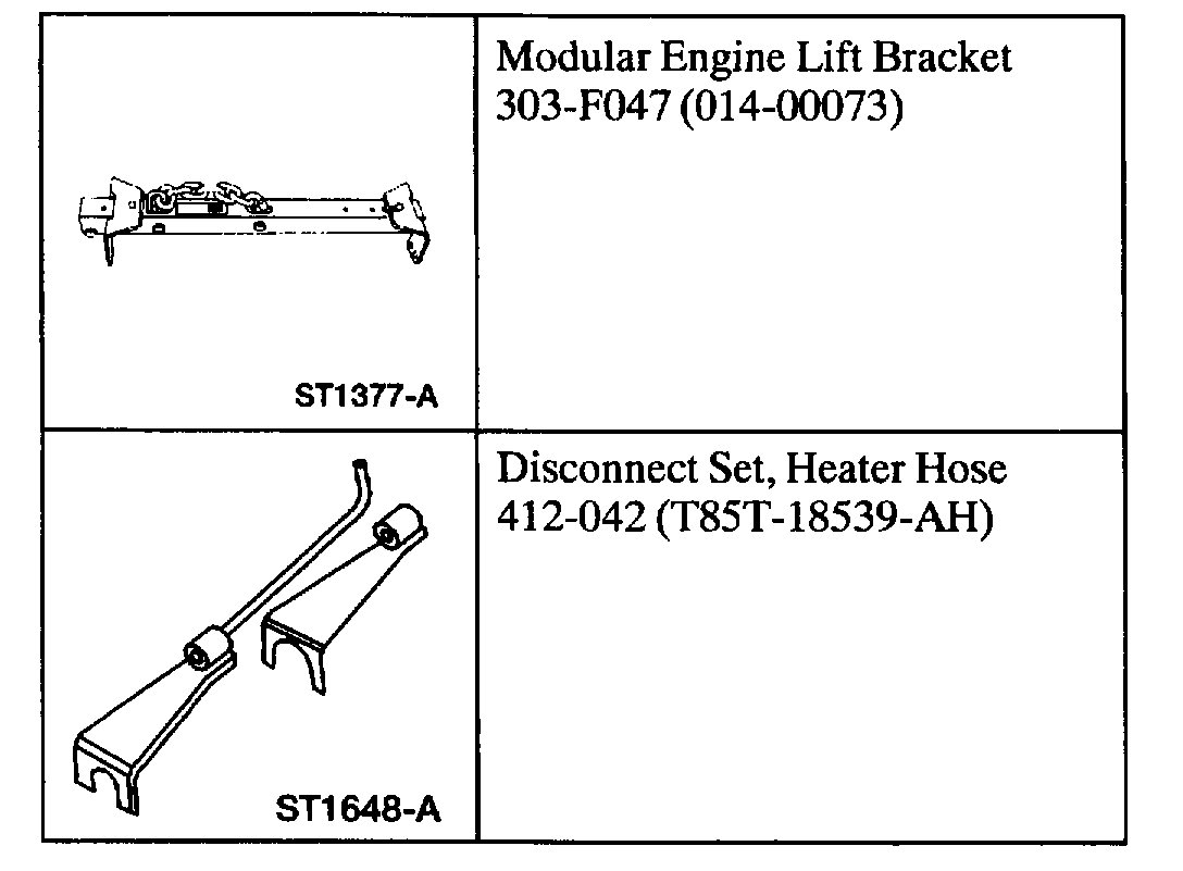
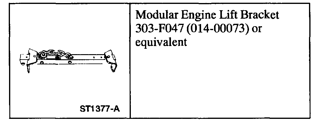
Special Tool(s)
Removal
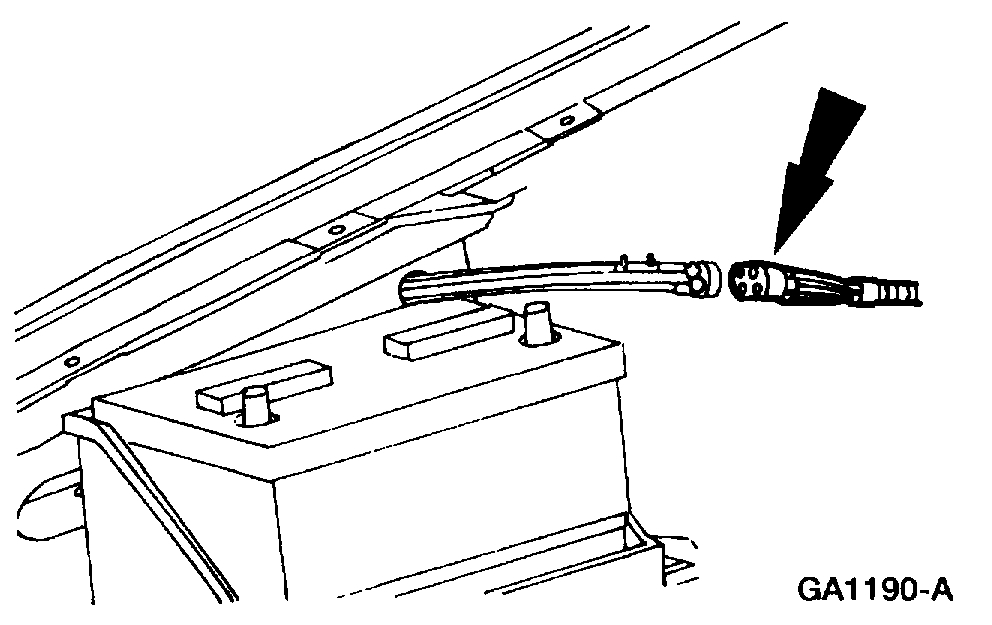
1. Disconnect the battery ground cable.
2. Remove the hood.
3. Remove the engine air cleaner.
4. Remove the A/C condenser core.
Pic 2
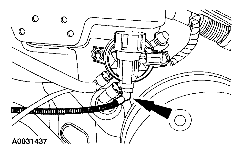
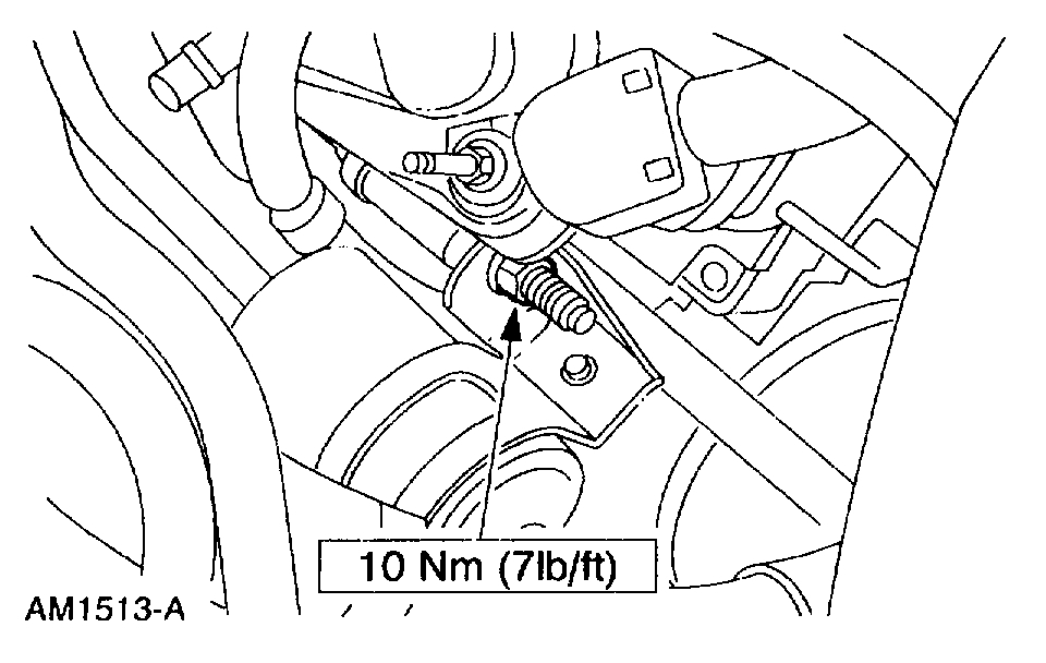
5. Disconnect the climate control vacuum connector.
Pic 3
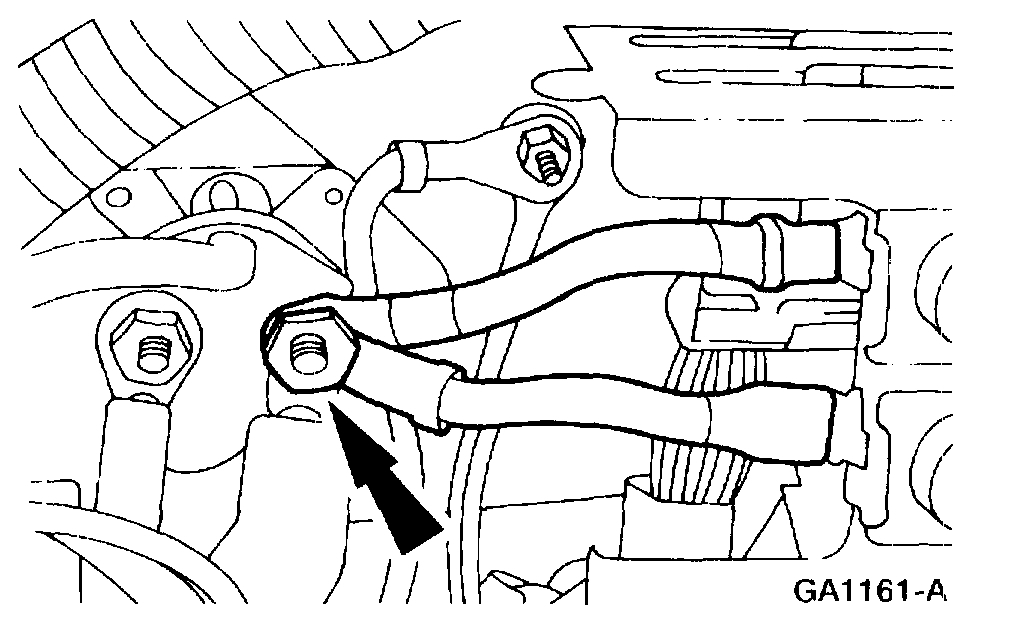
6. Disconnect the evaporative emission canister purge valve vacuum connector.
Pic 4
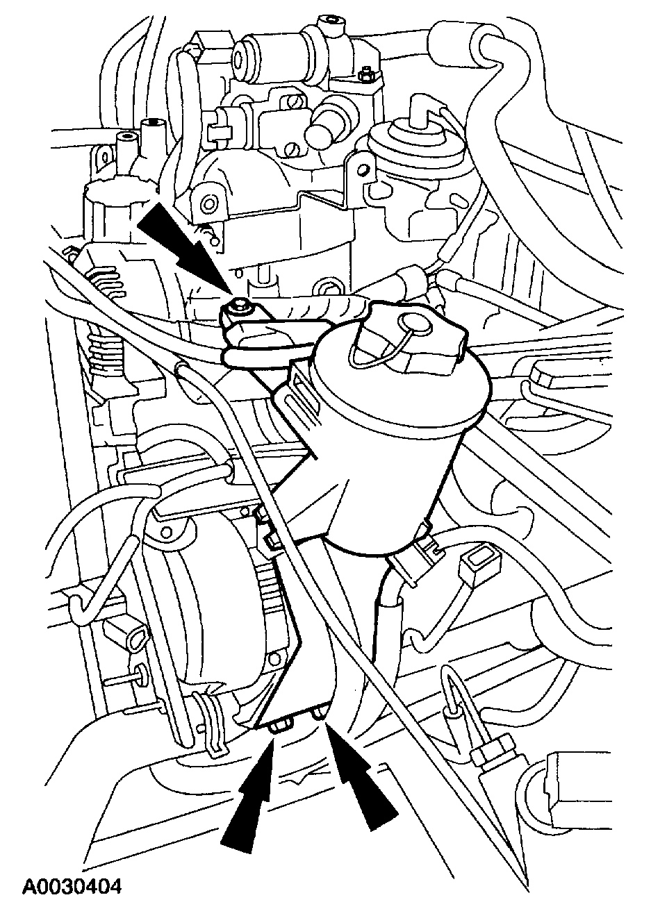
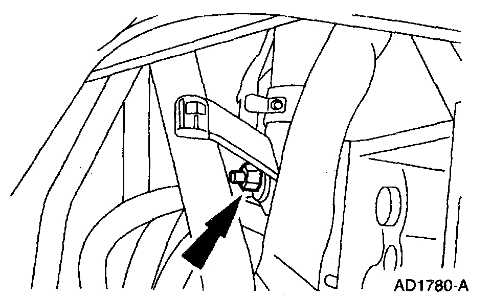
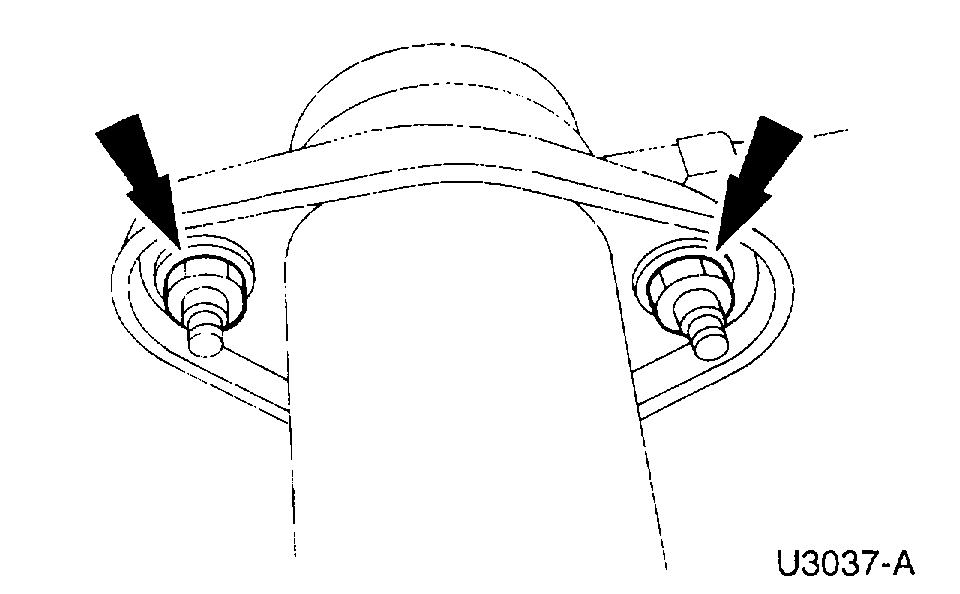
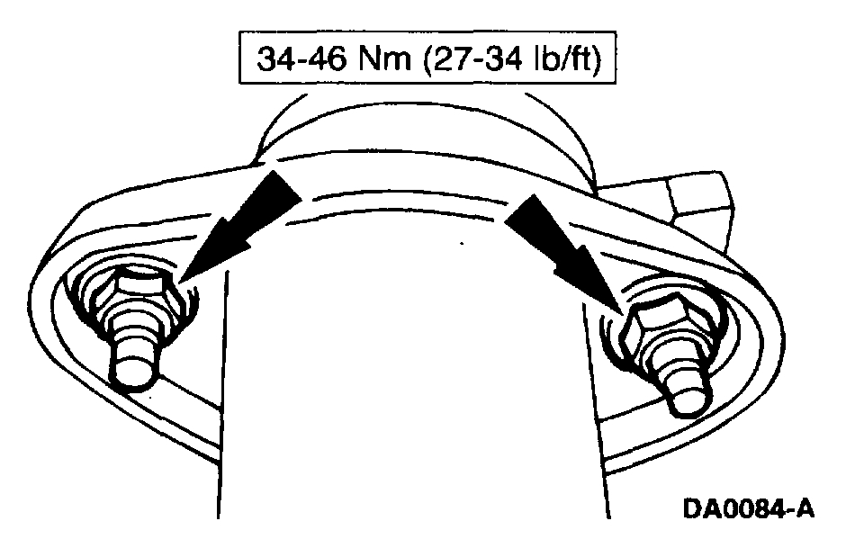
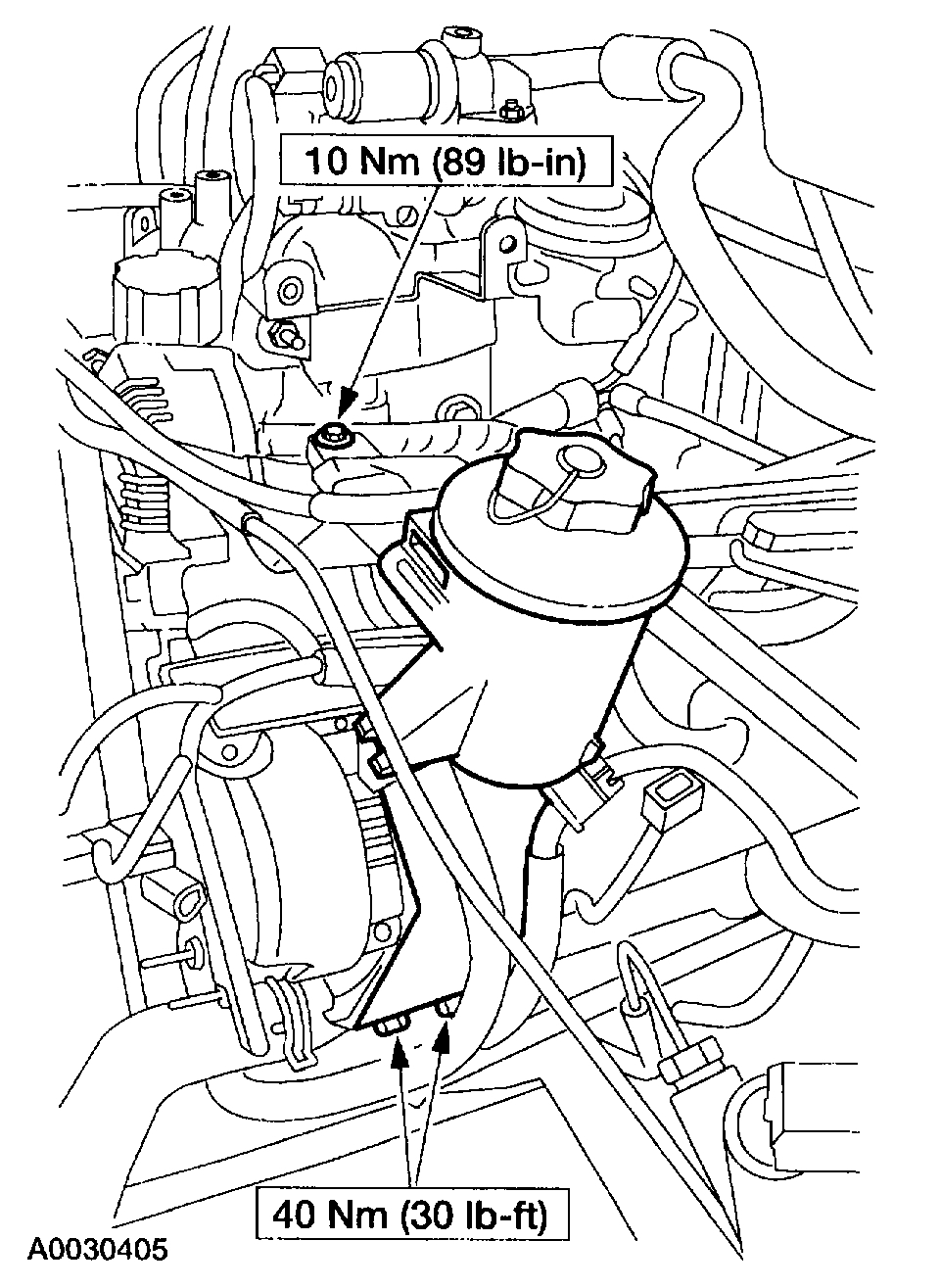
7. Position the power steering reservoir aside.
Remove the upper bolt.
Remove the lower bolts.
Position the reservoir aside.
8. Remove the intake manifold.
Pic 5
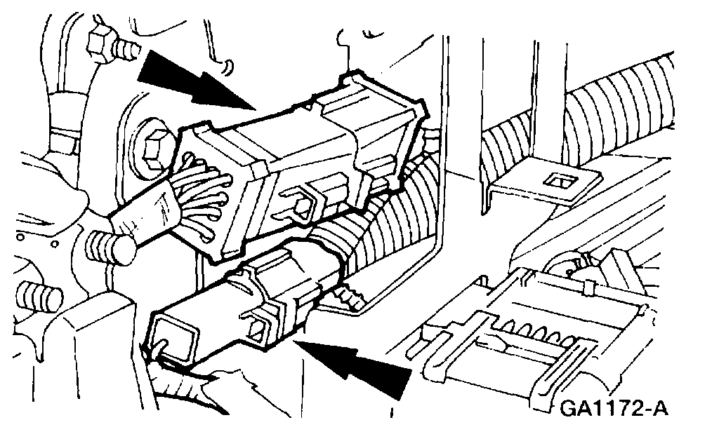
9. Disconnect the two starter cable leads from the starter relay.
Pic 6
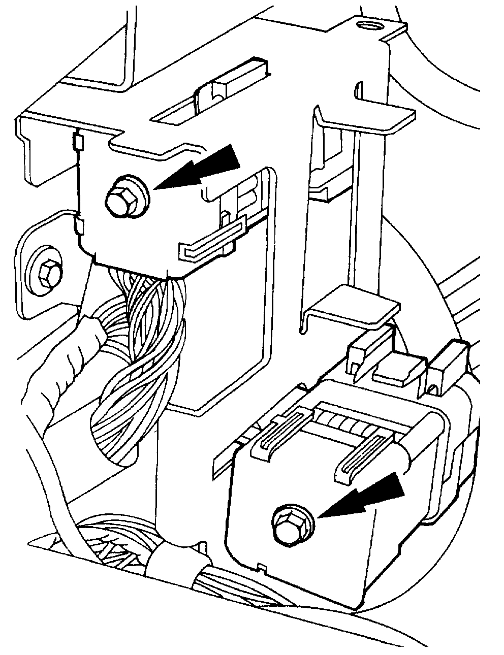
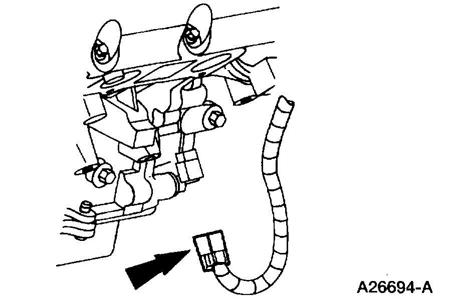
10. Disconnect the two 42-pin connectors and the single pin connector.
Pic 7
11. Disconnect the 16-pin connector and the single pin connector.
Pic 8
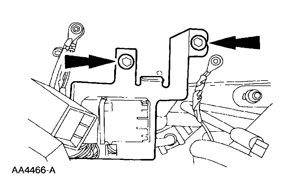
12. Remove the bolts and the junction block bracket.
Pic 9
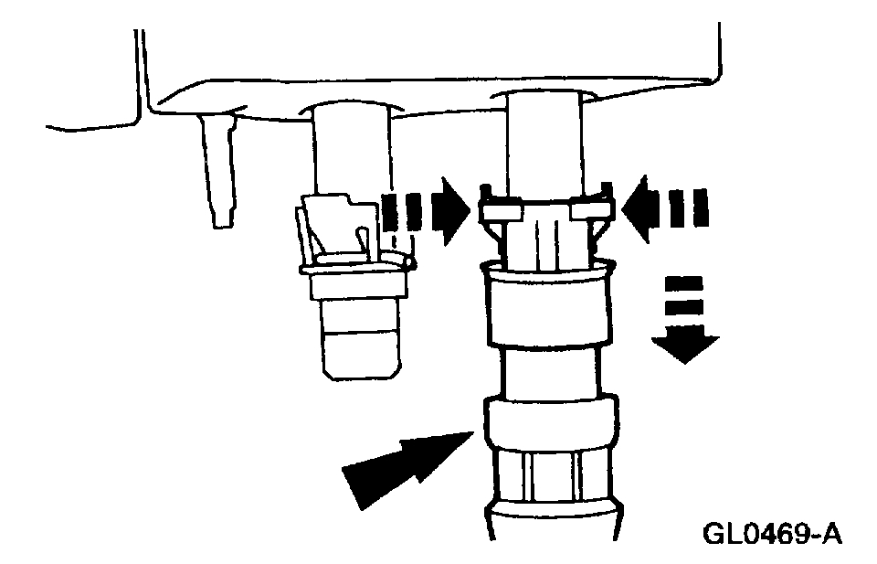
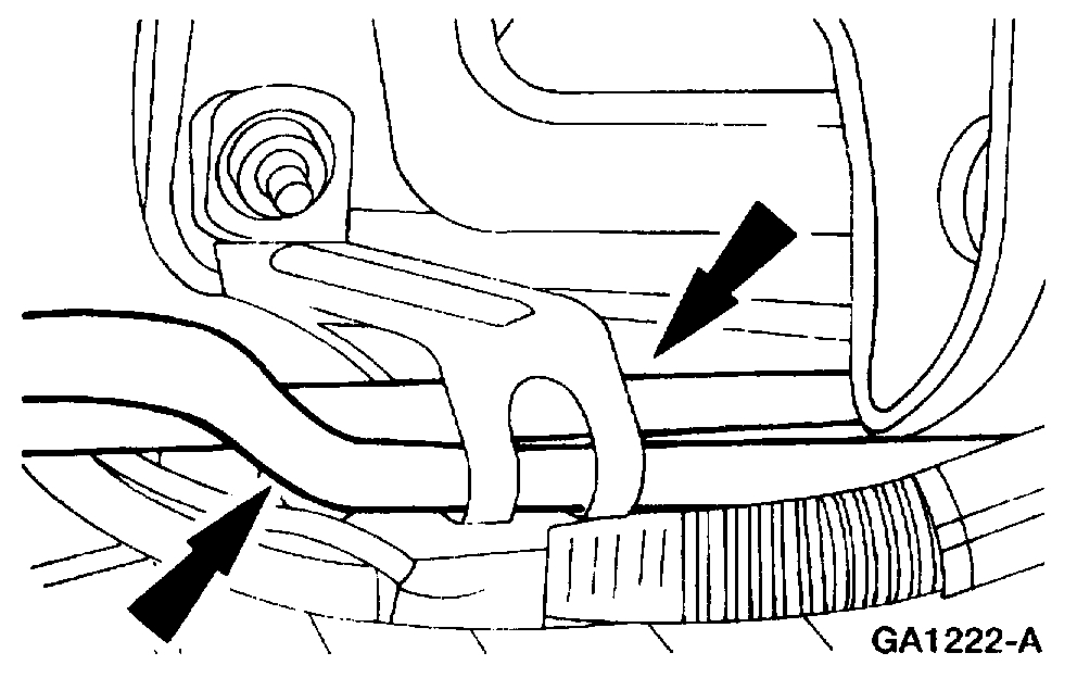
13. Compress the holding tabs and disconnect the heater water hoses from the heater core.
14. Raise and support the vehicle.
Pic 10
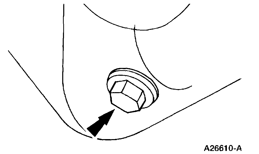
15. Remove the drain plug and drain the engine oil.
Pic 11
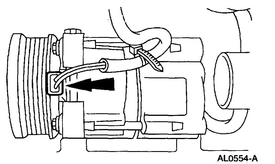
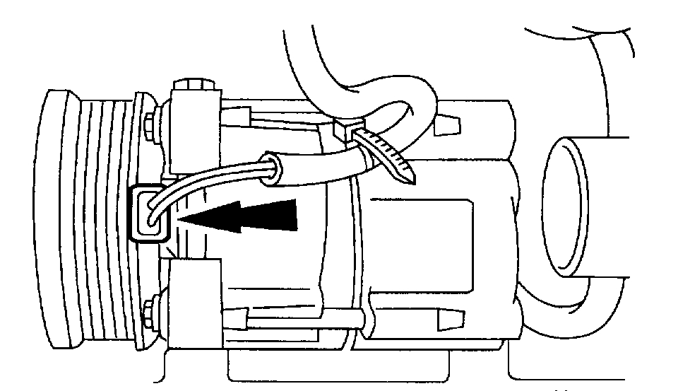
16. Disconnect the A/C compressor electrical connection.
Pic 12
17. Disconnect the crankshaft position (CKP) sensor.
18. Remove the starter motor.
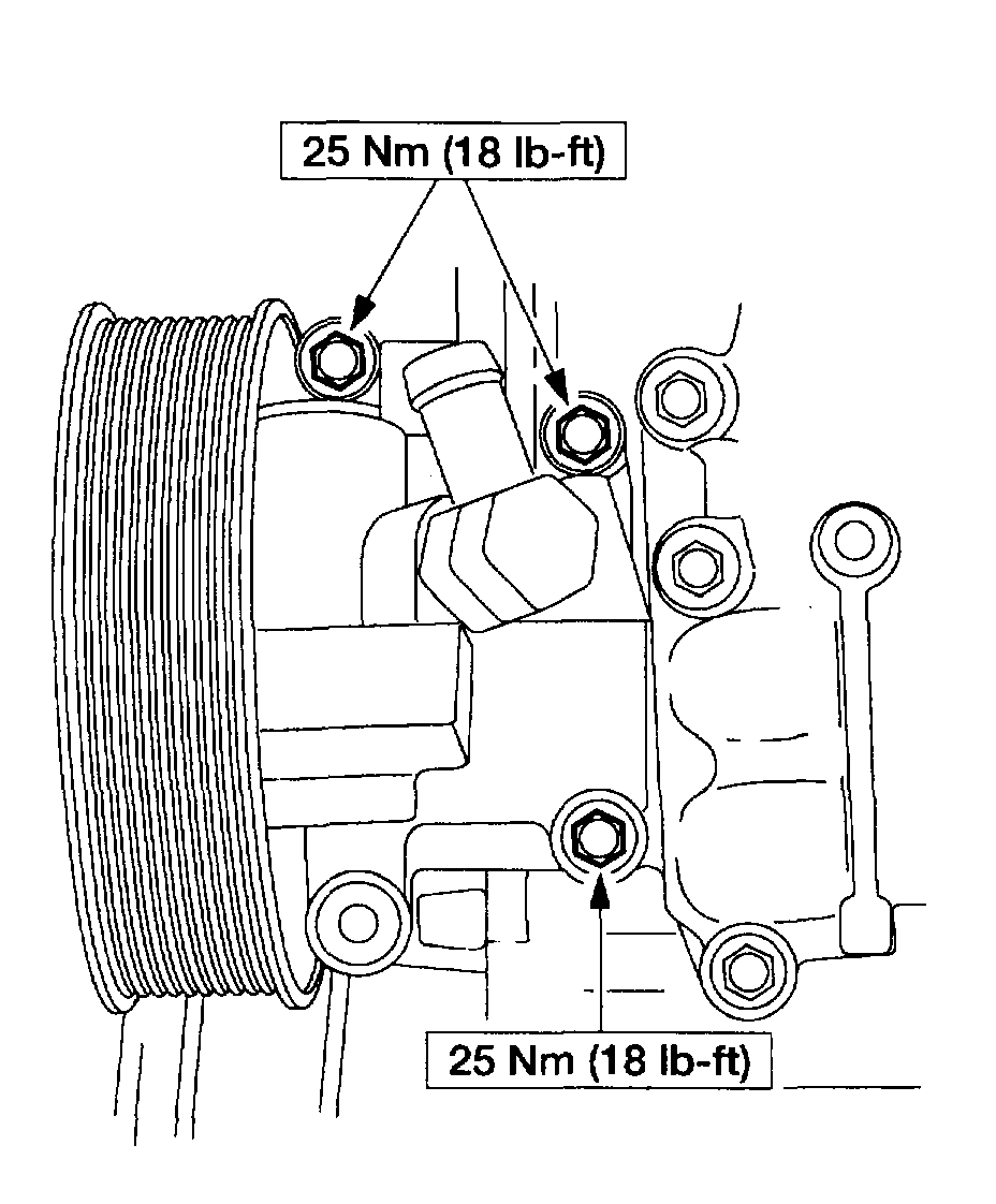
19. Remove the A/C compressor.
Pic 13
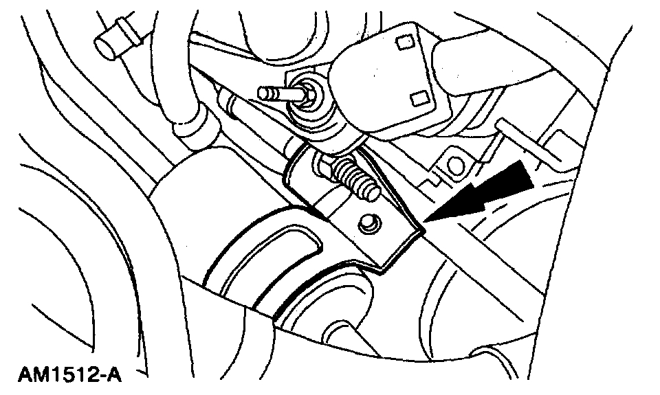
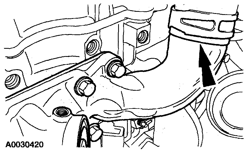
20. Remove the A/C line (muffler) bracket and position aside.
Pic 14
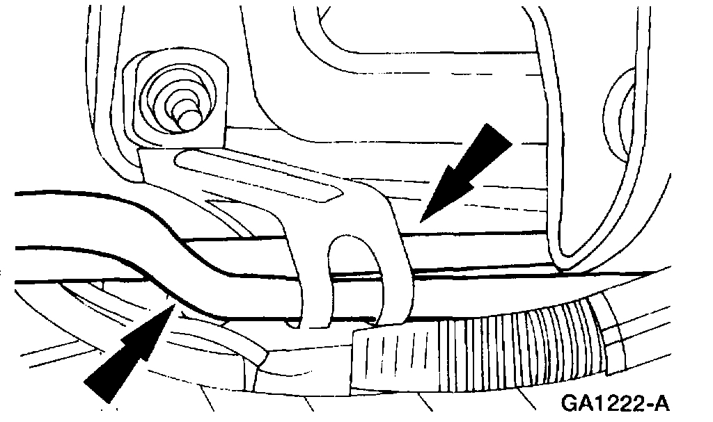
21. Remove the transmission fluid cooler hose from the block-mounted clip.
22. NOTE: The upper two transmission bell housing bolts will be removed later.
Remove the transmission inspection cover, torque converter bolts and transmission-to-engine block bolts.
Pic 15
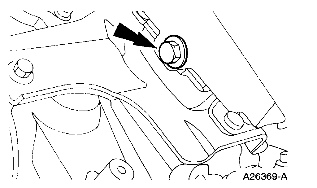
23. Remove the nut and the transmission oil filler tube.
Pic 16
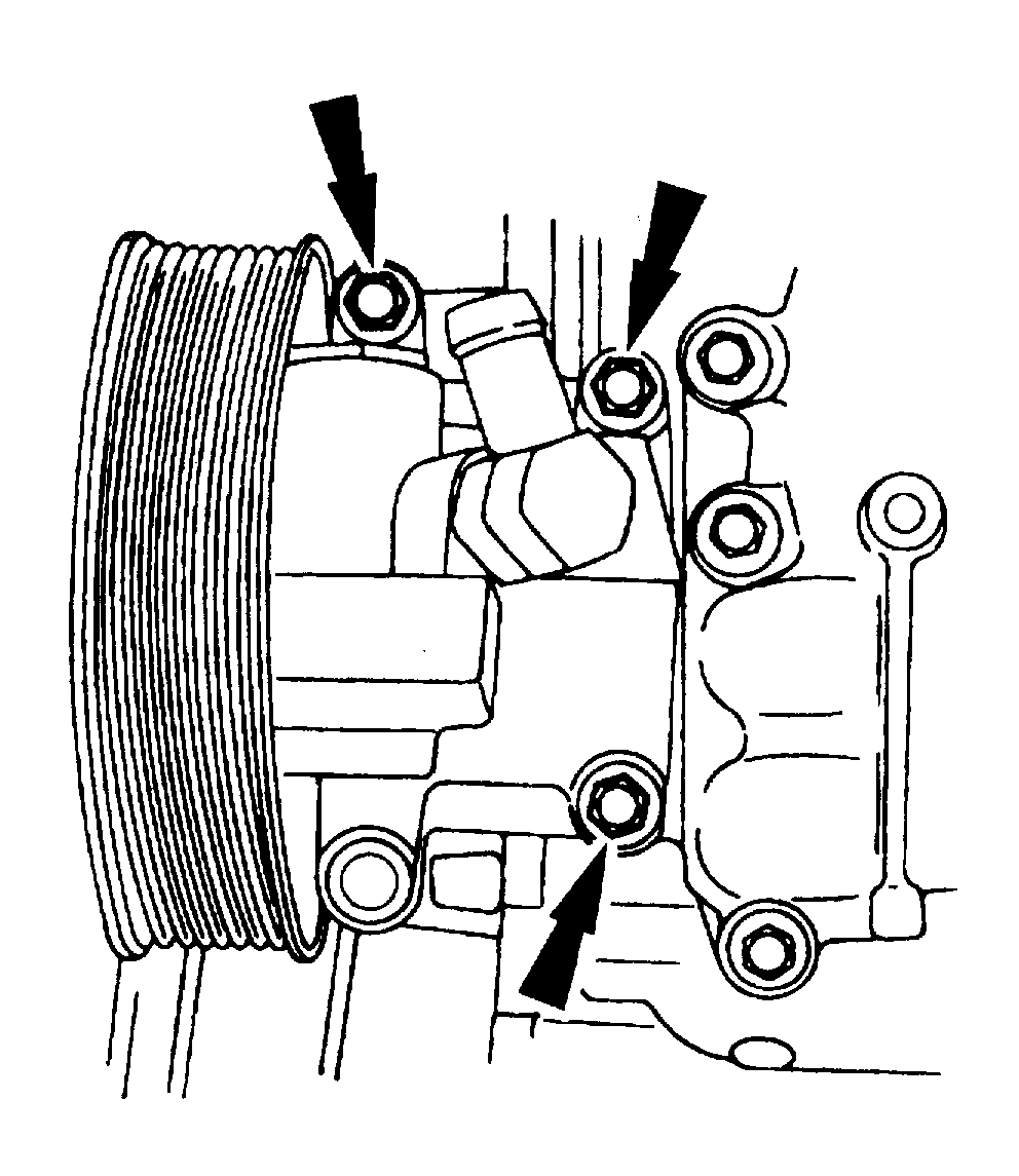
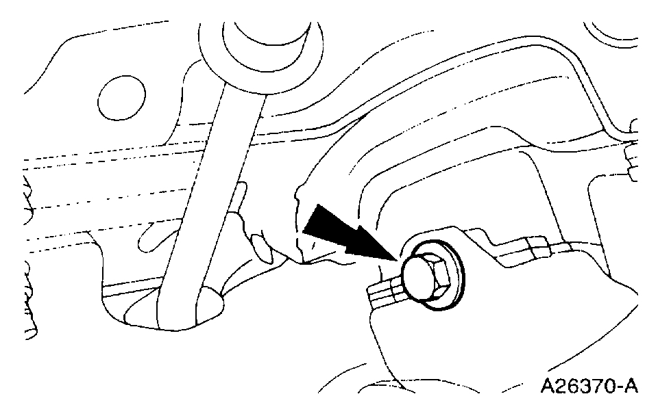
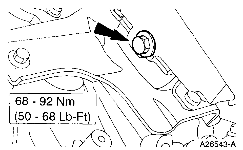
24. Remove the bolts and position the power steering pump aside.
Pic 17
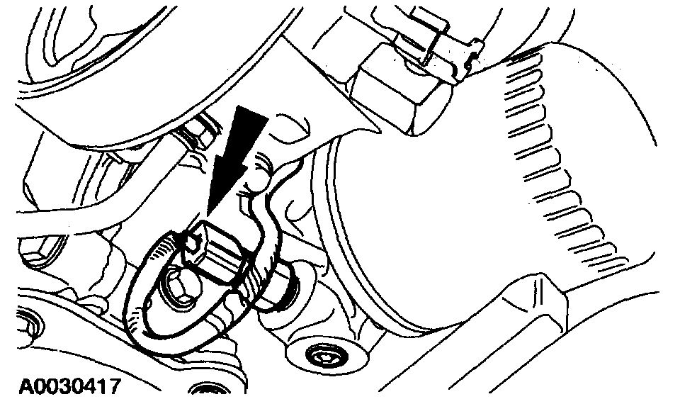
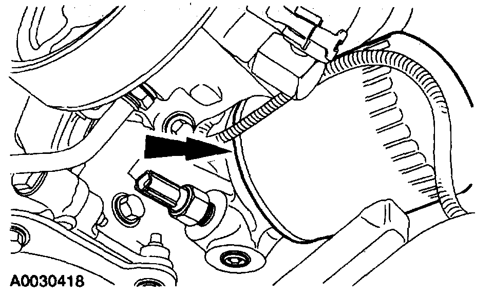
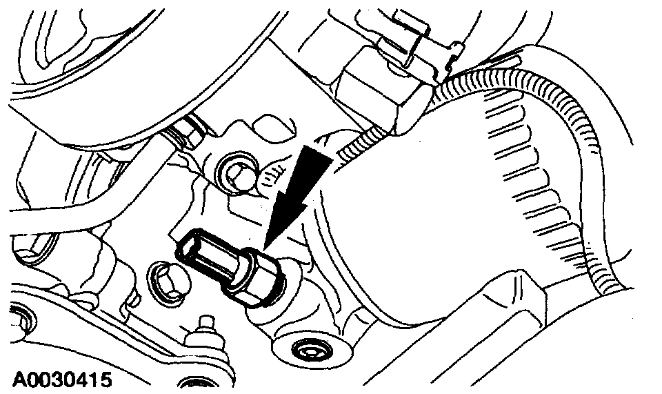
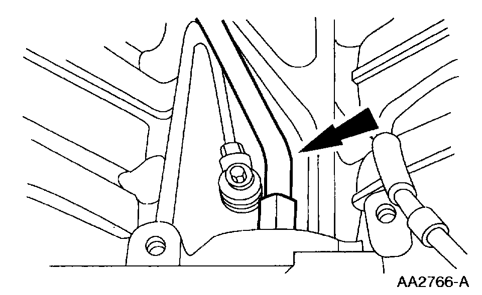
25. Disconnect the oil pressure sender electrical connection.
Pic 18
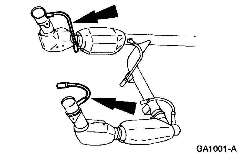
26. Disconnect the heated exhaust gas oxygen sensor electrical connectors.
Pic 19
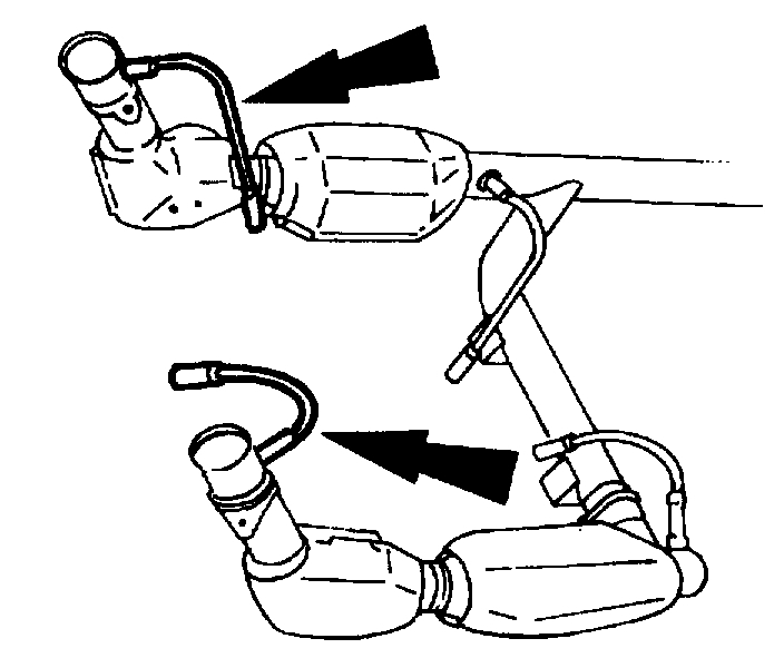
27. Remove the RH exhaust manifold to three-way catalytic converter nuts.
28. Remove the RH exhaust manifold studs.
Pic 20
29. Remove the LH exhaust manifold to three-way catalytic converter nuts.
Position the Y-pipe aside.
Pic 21
30. Remove the RH motor mount bolt.
Pic 22
31. Remove the LH motor mount bolt.
Pic 23
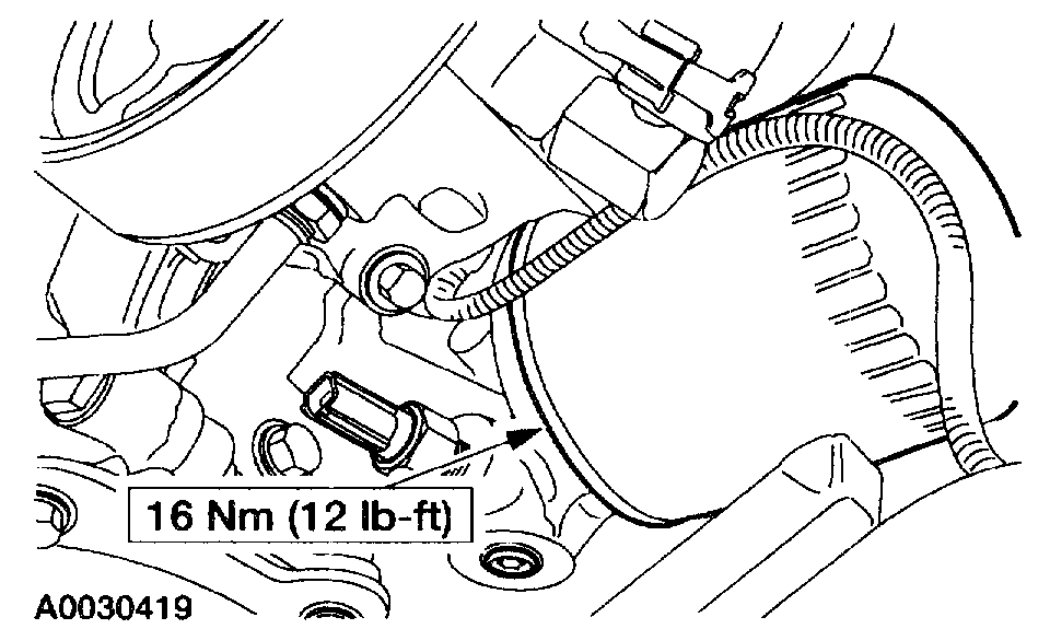
32. Remove the oil bypass filter.
Pic 24
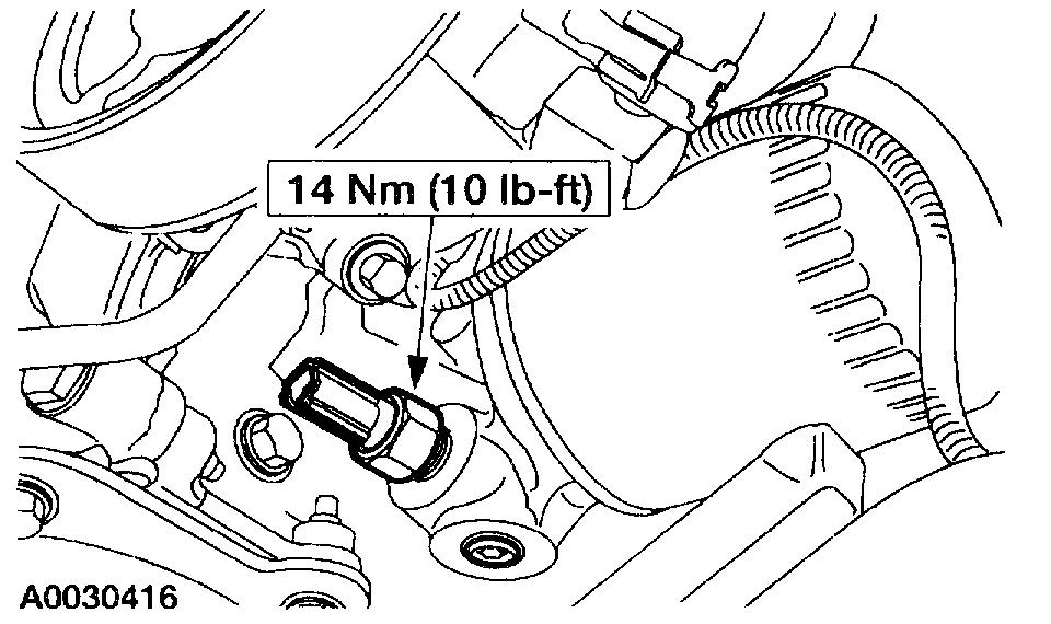
33. Remove the oil pressure sensor.
Pic 25
34. Slide back the hose clamp and disconnect the lower radiator hose from the oil filter adapter.
35. Lower the vehicle.
36. Support the transmission.
37. Remove the upper two transmission bell housing bolts and the wiring harness bracket.
Pic 26
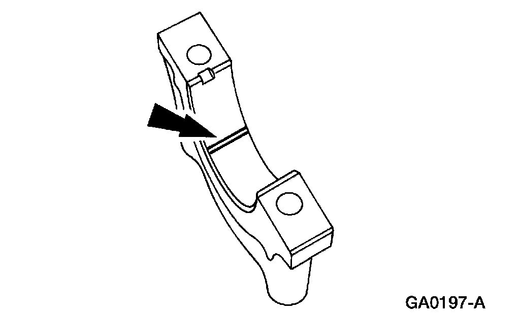
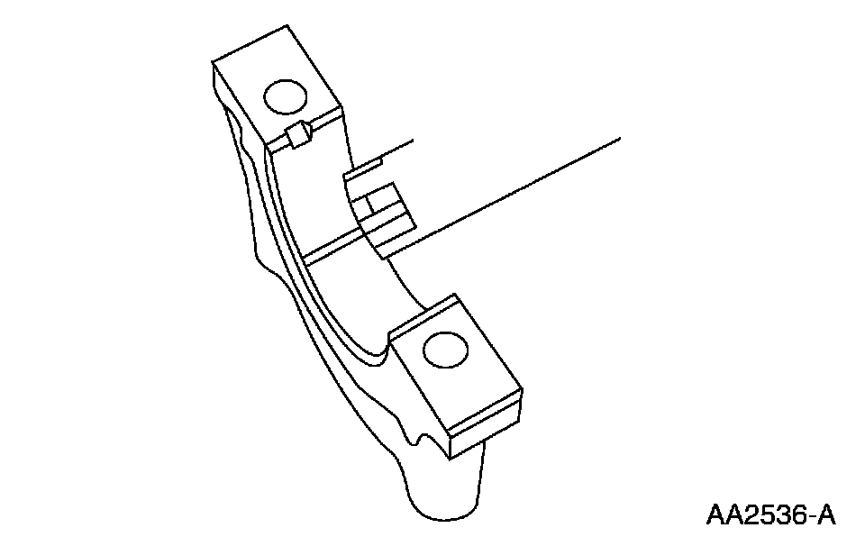
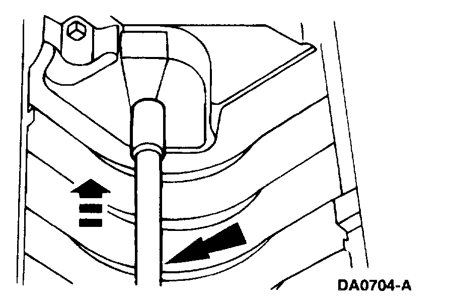
38. Remove the heater water inlet tube and discard the O-ring seal.
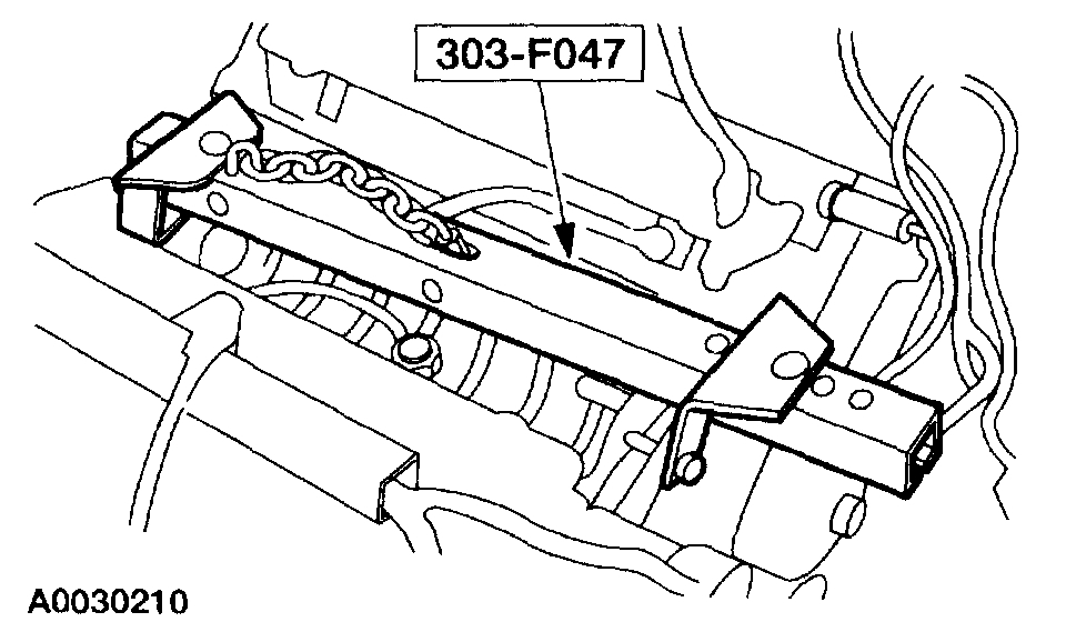
Pic 27
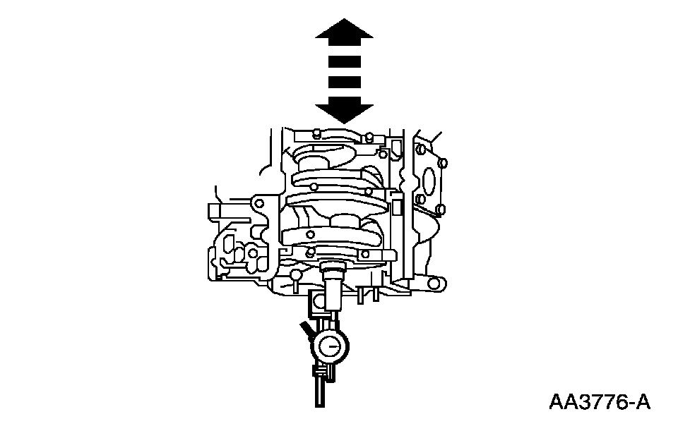
39. Install the special tool.
40. Remove the engine.
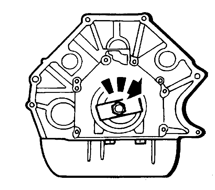
Pic 28
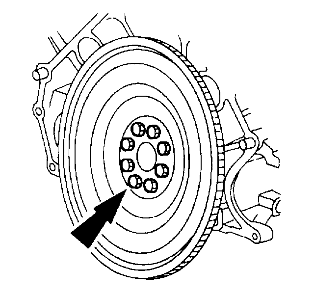
41. NOTE: Windsor engine shown.
NOTE: If engine disassembly is to be carried out, remove the rear crankshaft oil seal slinger and the crankshaft rear oil seal.
Remove the flywheel.
42. Place the engine on a suitable engine stand.
________________________________
Install
2001 Ford Truck F 150 4WD Pickup V8-5.4L SOHC VIN L
Installation
Vehicle Engine, Cooling and Exhaust Engine Service and Repair Procedures Engine Installation
INSTALLATION
pic 29
Special Tool(s)
Installation
pic 30
All vehicles
1. Attach the special tool.
2. Remove the engine from the engine stand.
3. CAUTION: Do not use metal scrapers, wire brushes, power abrasive discs or other abrasive means to clean the aluminum retainer plate. These tools cause scratches and gouges, which make leak paths. Use a plastic scraping tool to remove all traces of old sealant.
If removed, clean and inspect the mating surface.
Pic 31
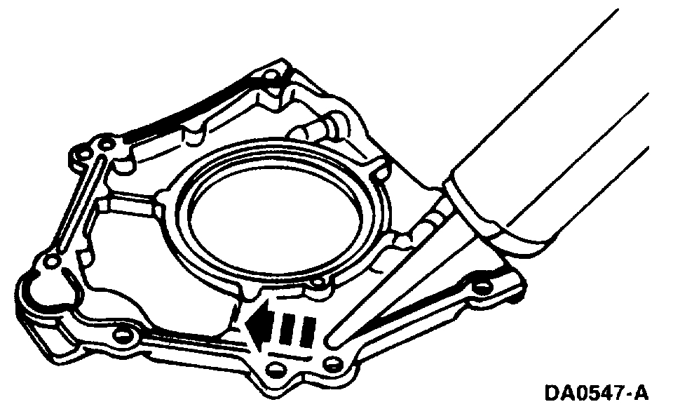
4. NOTE: If not secured within four minutes, sealant must be removed and sealing area cleaned with metal surface cleaner. Allow to dry until there is no sign of wetness, or four minutes, whichever is longer. Failure to follow this procedure can cause future oil leakage.
If the retainer plate was removed, apply a 4 mm (0.16 inch) bead of silicone gasket and sealant around the rear oil seal retainer sealing surface.
Pic 32
5. If removed, install the crankshaft rear oil seal retainer and bolts.
Pic 33
6. If removed, install a new crankshaft rear oil seal.
7. If removed, install the crankshaft oil slinger.
Pic 34
Romeo engine (4.6L)
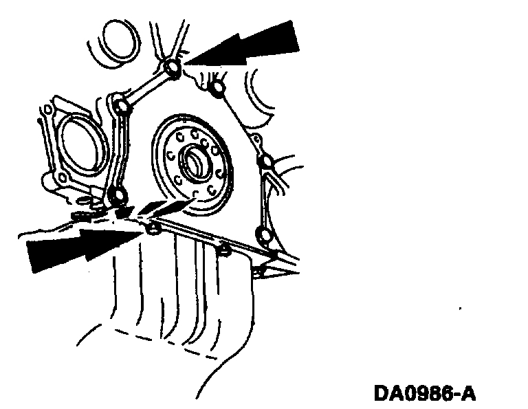
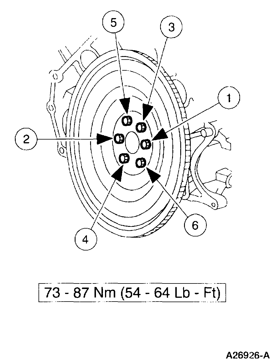
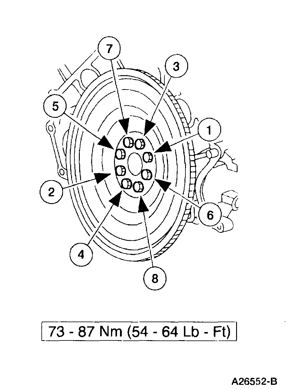
8. Install the flexplate and the bolts. Tighten the bolts in the sequence shown.
Pic 35
Windsor engine (SAL)
All vehicles
9. NOTE: Align the engine-to-transmission dowels before installing engine to transmission bolts.
Position the engine in the vehicle, and remove the Modular lifting bar and the jack supporting the transmission.
10. Raise and support the vehicle.
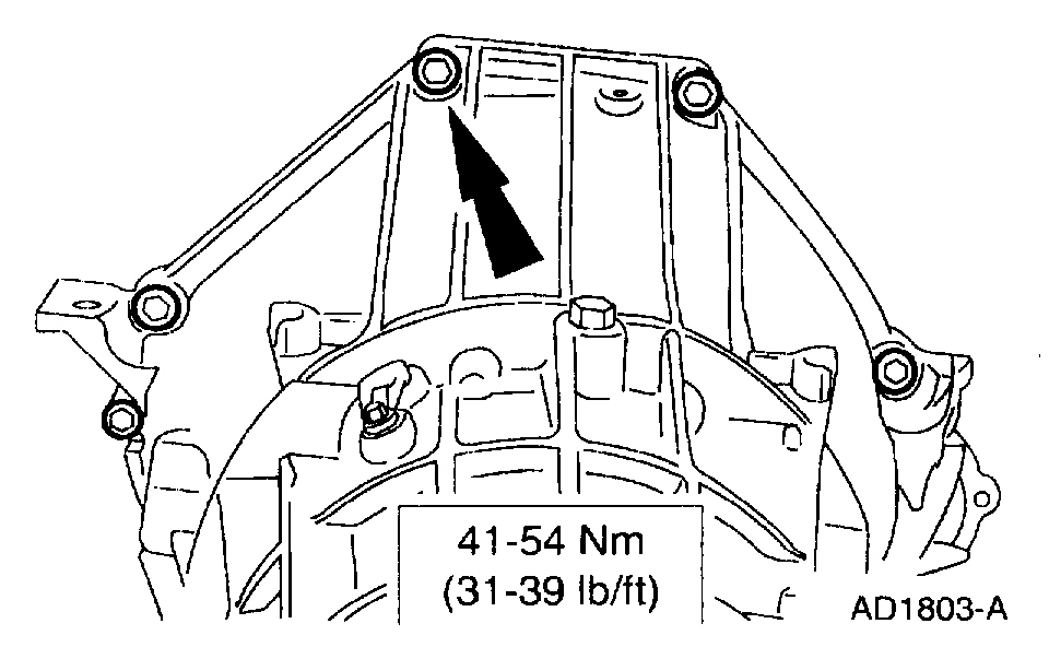
11. Install the lower five transmission bell housing bolts.
Pic 36
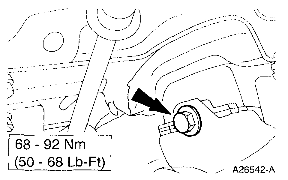
12. Position and install and the LH engine mount bolt.
Pic 37
13. Position and install the RH engine mount bolt.
14. Install the starter motor.
15. Install the A/C compressor.
16. Install the RH exhaust manifold studs.
Pic 38
17. Install and tighten the four nuts.
Pic 39
18. NOTE: Only three bolts are required for installation.
Install the bolts.
Pic 40
19. Position the lower radiator hose on the oil filter adapter and secure the hose clamp.
Pic 41
20. Install the oil bypass filter.
Pic 42
21. Install the oil pressure sensor.
Pic 43
22. Connect the oil pressure sensor electrical connector.
Pic 44
23. Install the transmission fluid cooler hose in the clip.
Pic 45
24. Install the A/C line (muffler) bracket.
Pic 46
25. Connect the A/C compressor electrical connector.
Pic 47
26. Connect the crankshaft position sensor electrical connector.
Pic 48
27. Connect the heated exhaust gas oxygen sensor electrical connectors.
28. Lower the vehicle.
Pic 49
29. NOTE: Lubricate the O-ring seals with transmission fluid.
Install the transmission oil filler tube and nut.
Pic 50
30. NOTE: Do not reuse the O-ring seal.
On Windsor engines, slide the water heater tube forward over the new O-ring seal.
Lubricate the O-ring seal with engine coolant.
Pic 51
31. Position the transmission wiring bracket and install the upper two transmission bell housing bolts.
32. Connect the transmission wiring harness connectors.
33. Install the intake manifold.
34. Install the A/C condenser.
35. Install the radiator.
36. Install the two heater hoses at the heater core.
Pic 52
37. Install the power steering reservoir.
Position the reservoir.
Install the two lower bolts.
Install the upper bolt.
38. Install the engine air cleaner (ACL) and the air cleaner outlet tube.
39. Fill all fluids to the correct levels.
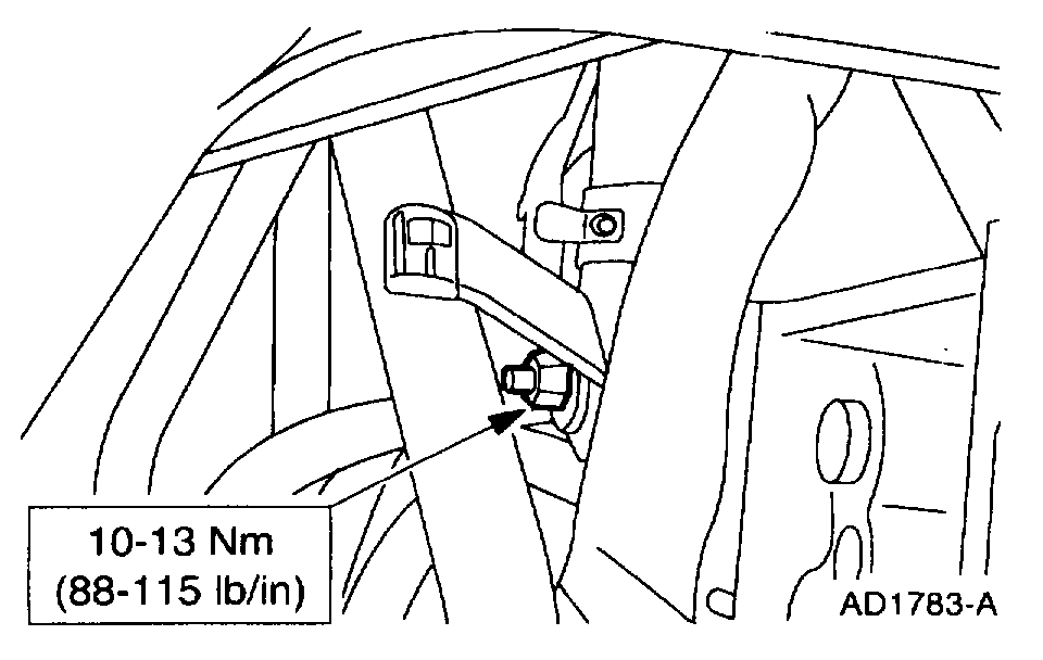
40. Connect bulkhead connectors.
Tighten the bolt.
41. Install the hood.
42. Connect the battery ground cable.
43. Start the engine and check for leaks. Stop the engine and recheck the fluid levels.
44. Recharge the A/C system.
__________________________________
I hope this helps. Let me know if you have any questions.
Take care,
Joe
Images (Click to make bigger)
Sunday, November 15th, 2020 AT 6:10 PM