Intermittent hard start, stalling and crank no start, with multiple codes?

Tiny
DAVID DAVO ESSIEN
  • MEMBER
  • 2005 CHRYSLER 300
  • 3.5L
  • V6
  • 2WD
  • AUTOMATIC
  • 150,127 MILES
I was called to another garage to fix the car listed above 300c. The problems they noticed with the car was Hard or no start, no throttle response, battery and ESP light remaining on, most times immediate stalling after starting however, if it doesn't stall there's a rough idle throughout idling as a result an old PCM was replaced with a new one however problem still persisted. 

  I did all system scan and saw a P0340, P2167, P2166, P2115, P2116, p0603 and more module codes like C2202, U0168, U1414, B1A25, etc.
Only DTC scan I got p0403, p0403, p0340, p0052, p0058
Please, how can I fix these problems?
Wednesday, August 2nd, 2023 AT 4:10 AM

33 Replies

Tiny
AL514
  • MECHANIC
  • 4,120 POSTS
Hello, so you got all the first set of codes on your first full system scan, and then did you erase them all and got the last 4 back? Is that what happened? The no start issue alone is most likely the U0168 PCM lost comms with the SKREEM module(Security system).
Do you still have to old PCM? With this many codes there has to be some kind of bulk connector issue/ wiring issue. Do any of the APP codes come back (P2167-P2116)?
The B1A25 Invalid Key would prevent starting as well. I would put the old PCM back in it to begin with, at least that way the old PCM has all the correct data for the security system and key.
I would check the PCM connectors for pit tension as well. Who knows how many times connectors on this vehicle were disconnected and the harness messed with and moved around.
The 02 sensor heater circuits High codes mean the PCM is not seeing those heater circuits being pulled to ground. They are usually pulse width modulated on the ground side for control, but I'll look that up
Does this vehicle have the Autostick option?

This code is also a main concern (P0603) PCM Keep Alive Memory failed. This is the constant power feed to the PCM

Start with seeing if there is a 5v reference at any 3-wire sensor, just to make sure its a full 5volts, Id check a few sensors, the MAP, CAM pos, Crank Pos, APP (accel pedal pos), some of the sensors setting codes use the same 5volt Ref.
And the check the Keep Alive Memory at the PCM, Ill post a diagram for it, but it comes from Fuse 23 15Amp in the engine compartment fuse block.

Below is the PCM connector C1 with the Keep Alive Memory feed, a few Ignition switch feeds and some PCM Grounds.
Was this
answer
helpful?
Yes
No
+1
Wednesday, August 2nd, 2023 AT 9:48 AM
Tiny
DAVID DAVO ESSIEN
  • MEMBER
  • 143 POSTS
I checked the CMP and the CAN resistance at the OBD2 port. But the major challenge the owner wants to be fixed permanently is the car security light that would stay on and hinder the car from starting but when it blinks, and battery light goes off the car would start. Others would be addressed later.
Was this
answer
helpful?
Yes
No
Wednesday, August 2nd, 2023 AT 10:47 AM
Tiny
AL514
  • MECHANIC
  • 4,120 POSTS
That's why I think putting the old PCM back in would be good. The new PCM might not be programmed correctly, but with so many codes, I think you're going to find a wiring issue. That is probably affecting the security system as well, if this is an intermittent problem. Plus, if the PCM is not maintaining its KAM memory, which is going to mess with things too. Even if you have the correct termination resistance on the CANbus network, which doesn't mean there isn't a module sending out corrupt data packets. Have you scoped the CANbus data wires?
The Sentry Key entry module communicates on the CAN B bus to the Front Control Module which acts as a gateway to the CAN C bus which is what the PCM communicates on to the network. There are 2 different CAN networks so a resistance check at the DLC only checked the CAN C network not the CAN B. So, if there's a corroded series connector somewhere there might be communications problems between the Security system and PCM
The 2nd diagram below is the code C2202 ORIGINAL VIN Mismatching/Missing.
So, the ABS module is also seeing the incorrect VIN number

U1414 IMPLAUSIBLE/MISSING ECU CONFIGURATION DATA
U0168 PCM lost comm w/ secu SKREEM
B1A25 INVALID KEY
Was this
answer
helpful?
Yes
No
+1
Wednesday, August 2nd, 2023 AT 11:13 AM
Tiny
DAVID DAVO ESSIEN
  • MEMBER
  • 143 POSTS
Thank you for the diagram and guide. My scan tool is not compatible to scoping of the CAN BUS, I used a multimeter for CAN check.
Was this
answer
helpful?
Yes
No
Friday, August 4th, 2023 AT 4:59 AM
Tiny
DAVID DAVO ESSIEN
  • MEMBER
  • 143 POSTS
There are even more codes.
Was this
answer
helpful?
Yes
No
Friday, August 4th, 2023 AT 5:22 AM
Tiny
DAVID DAVO ESSIEN
  • MEMBER
  • 143 POSTS
More codes still. Please, I'm sorry. It's not a 300c but it's a 300 limited instead. That's what I saw, I don't know the difference though.
Was this
answer
helpful?
Yes
No
Friday, August 4th, 2023 AT 5:41 AM
Tiny
AL514
  • MECHANIC
  • 4,120 POSTS
They make a 300 that has a V8 Hemi in it, the "300" is just the name of the vehicle. I have a friend that has a 300 5.7Liter Hemi and it's a beast. And yes, you do have a ton of codes there. I'm going to write all these down and try to see if there is anything in common with them. This is going to be a wiring issue with a bulk connector possibly being corroded inside. But I want to have all these codes down in a folder for you. For scoping a network, I use a Pico scope, it's not a scan tool-based scope. But let me go over all these codes and see if there is a bulk connector that you can check. For now, that's what I would be doing, just start checking connectors that have bunches of wires, or module connectors that might have been exposed to water intrusion.
If you are interested in getting into scope use, you can get a 2 channel Pico scope for around $150 and the software is free, check it out. Picotech. Com

What does it say above Central Gateway? Which module is that?
Was this
answer
helpful?
Yes
No
+1
Friday, August 4th, 2023 AT 9:37 AM
Tiny
DAVID DAVO ESSIEN
  • MEMBER
  • 143 POSTS
Please, can you also provide me with the engine bay and rear fuses description for the car? The reason for that is, when testing the rear fuses with a test light connected to ground without the ignition turned to Acc position that's fuse 31 precisely, it lit the test light though however, relay number 21 actuated. Thus, I pulled it out and checked the relay circuit and noticed this. What could be responsible for that; and could it be responsible for the flashing and steady security light? In addition, is there a guide to fix the security problem or even disabling it? The only thing that the client has been doing if the security light stays on and doesn't start is to unplug battery terminal wait for some minutes and then reconnect it. But he said he doesn't want it that way again.
Was this
answer
helpful?
Yes
No
Friday, August 4th, 2023 AT 9:53 AM
Tiny
AL514
  • MECHANIC
  • 4,120 POSTS
Well, it's not that simple, if a module here is affecting the network, and with this many codes there is definitely something going on more than just the security system, the vehicle is still going to have running conditions. I mean there are codes such as Ignition Run Control 1 Circuit Open, Ignition Run Input Circuit Open, ECM in Single Wire mode, etc. Codes like this are going to prevent it from starting even if you happen to get the security system bypassed. Any temporary attempted fix like that is not going to do anything. This vehicle runs almost completely on the canbus system, this is not like GM where there are a bunch of modules on a 1 wire GMLAN network, and we could just unplug modules until we come across the fault. It's just not that simple.
If you erase all these codes which ones, come back first? I can have you check some of the canbus voltages with your multimeter and we can see if any are shorted to voltage or ground. The can runs on a bias 2.5volts, can high is 2.5 to about 3v and can low is 2.5 to around 2. So, if it's shorted to ground, you wouldn't read the bias 2, 5volts, if it's shorted to voltage you'll read around battery voltage.
Now if you want a module that is plug and plan and requires no programming, Flagship One can do that.
I'm checking right now to see if they can bypass the security.
Okay, they do bypass security when they program their modules. But that may not solve the starting issues. You can't just bypass security with the ECM that is in the vehicle right now, it needs to be reprogrammed. There are too many modules involved.

I will post the power diagrams for you, give me a minute.
Was this
answer
helpful?
Yes
No
+1
Friday, August 4th, 2023 AT 10:18 AM
Tiny
AL514
  • MECHANIC
  • 4,120 POSTS
Here are all the Power Distribution diagrams, each page is labelled top and bottom, so if you print them out, you can put them together.
Do you want Ground too?
Was this
answer
helpful?
Yes
No
+1
Friday, August 4th, 2023 AT 10:40 AM
Tiny
DAVID DAVO ESSIEN
  • MEMBER
  • 143 POSTS
Thank you so much for the diagrams. Sorry, I didn't include this from the onset. The client told me that "when that problem first started that the security light was constantly on hence the car didn't start at all but one among the people that have been invited to fix the car told them to clean some ground which temporary made the security light to flash again and started the vehicle. However, the constant security light didn't stop. The car still has constant security light and a no start.
Most importantly please, can you also provide me with the faulty reason for this electrical video?
When testing the rear fuses with a test light connected to ground without the ignition turned to off position most fuses lit the test light. Nevertheless, fuse 31 precisely, it lit the test light though too but also actuated relay number 21. Thus, I pulled the relay out and checked the relay circuit and noticed this. What could be responsible for that; and could it be responsible for the flashing and steady security light? Please, is it normal that way or something is wrong?
Was this
answer
helpful?
Yes
No
Friday, August 4th, 2023 AT 5:10 PM
Tiny
AL514
  • MECHANIC
  • 4,120 POSTS
Almost all the fuses in the rear fuse panel are hot all the time, they are not coming from the ignition switch, I don't see any fuse 31 anywhere or any relays numbered 21. I'm also not sure what electrical video you're referring to.

Looking over a lot of these codes, a bunch are related to the CAN B Bus network, and the Sentry Key Entry module, Instrument Cluster, Front Control module are all on that network, some of these codes have causes stated CAN B Bus shorted or open circuit. So, with the key on you should find a pair of the CAN B bus wires and see what the voltage reading is on them. CAN bus wires are always in a twisted pair. I'll find a module on that network that you can check the voltage level on each leg and see if either are shorted or if there is no signal at all.

Here's the location of the Front Control Module and connector C1 pins 2 and 3 which are the CAN B Bus wires, they will be a twisted pair, check each one to ground separately and then check across both wires for a bias 2.5-volts. See what voltage is on either wire with the key on. Write it down.
Was this
answer
helpful?
Yes
No
+1
Friday, August 4th, 2023 AT 5:52 PM
Tiny
DAVID DAVO ESSIEN
  • MEMBER
  • 143 POSTS
Thank you so much for the wiring diagram. Please to start with, since I'm not too conversant with CAN-BUS work, to access this CAN-B network especially and other CAN-BUS. I'll need to first disassemble or loose the instrument cluster, radio, etc, right? I'll check that and get back to you. Please later you can also guide me on how to bypass the modules even though it doesn't fix the starting problem. But I'll check what you advice me to do first. Thank you for all the guide!
Was this
answer
helpful?
Yes
No
Saturday, August 5th, 2023 AT 9:34 AM
Tiny
AL514
  • MECHANIC
  • 4,120 POSTS
No you don't need to disassemble anything, back probe the connector at the Front Control module in the diagrams I posted, the 2nd diagram is the engine compartment, the C1 connector is circled in yellow, you will need to back probe pins 2 and 3 so you can measure the voltage while the key is on, we need to see what the CAN B voltage level is. The Front Control Module is attached to the side of the Integrated Power module, everything is right there are the diagrams. Diagram 3 is the Front control module connector C1, pins 2 and 3 are the CAN B High and Low pins. Check each one first with your black multimeter lead on battery negative and the red lead on pin 2 first, then do the same for pin 3. Then finally check both pins with the meter leads on pins 2 and 3. We need to know if either of those pins is shorted to Ground, Power, or to each other.

https://www.2carpros.com/articles/can-scan-controller-area-network-easy
Was this
answer
helpful?
Yes
No
Saturday, August 5th, 2023 AT 10:10 AM
Tiny
DAVID DAVO ESSIEN
  • MEMBER
  • 143 POSTS
Thank you so much for the guide. Sorry, I didn't see the explanation earlier. Due to some factors - ranging from my phone. I was unable to access it as supposed. But I later fixed the phone's problem.
When I later went there, within the short period of time I pulled several things from the dashboard, radio, etc, remaining few bolts to completely pull it out. I tested the CAN at DTC with my multimeter set to continuity range I got a 061 ohms resistance.
In addition, I saw that the wires tightened to the metal body was really corroded hence I loosed and cleaned the surfaces. Some wires under instrument cluster was spliced and left to be naked that way. I fixed those ones too. Additionally, the power wire tightened to the engine compartment power distribution wire was pretty corroded and not properly tightened, I also corrected those.
Furthermore, I saw that the key transponder wasn't really tightened to the ignition assembly properly, one bolt was off causing it to wobble.
I tested the pins at the module power train control C1 black/black connector of the ECM and noticed that for pin 9 and 18 = 0.01v; pin 11, 12, and 29 =12.43, 12.32 and 12.49 volts; pin 30=0.06v ; pin 27 =5.02 volts. Those were the few things I checked.
Was this
answer
helpful?
Yes
No
Sunday, August 6th, 2023 AT 10:39 AM
Tiny
AL514
  • MECHANIC
  • 4,120 POSTS
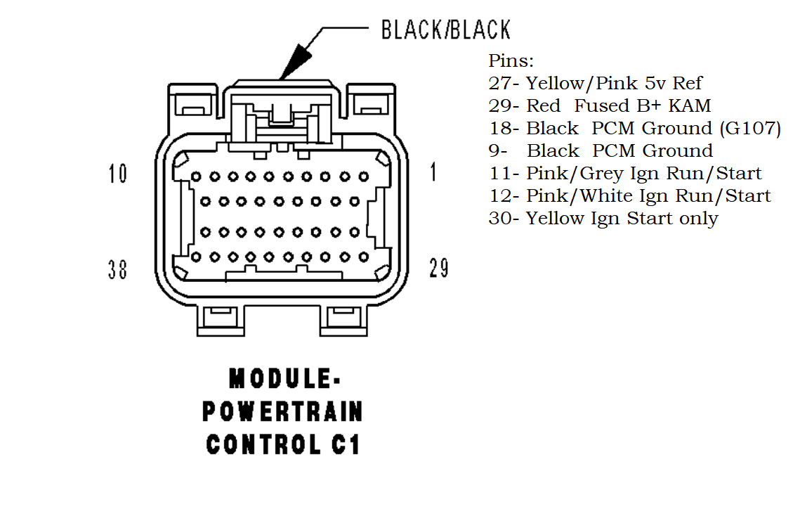
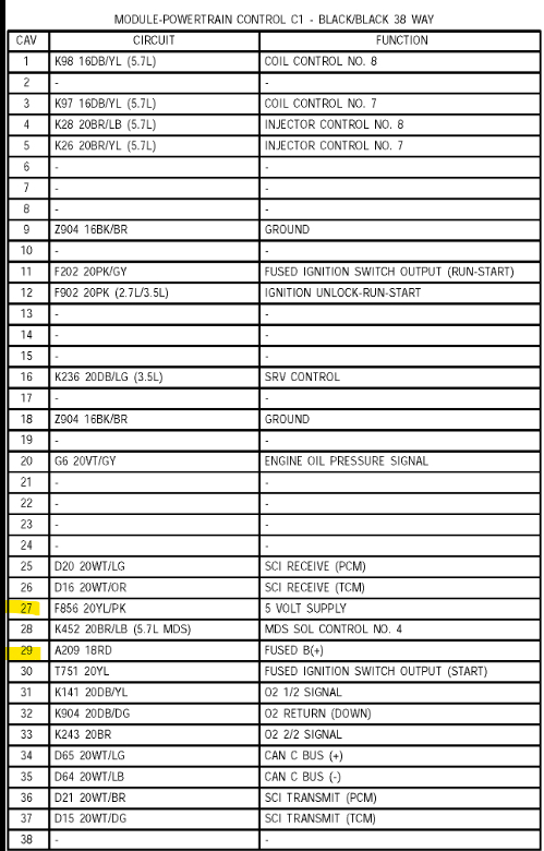
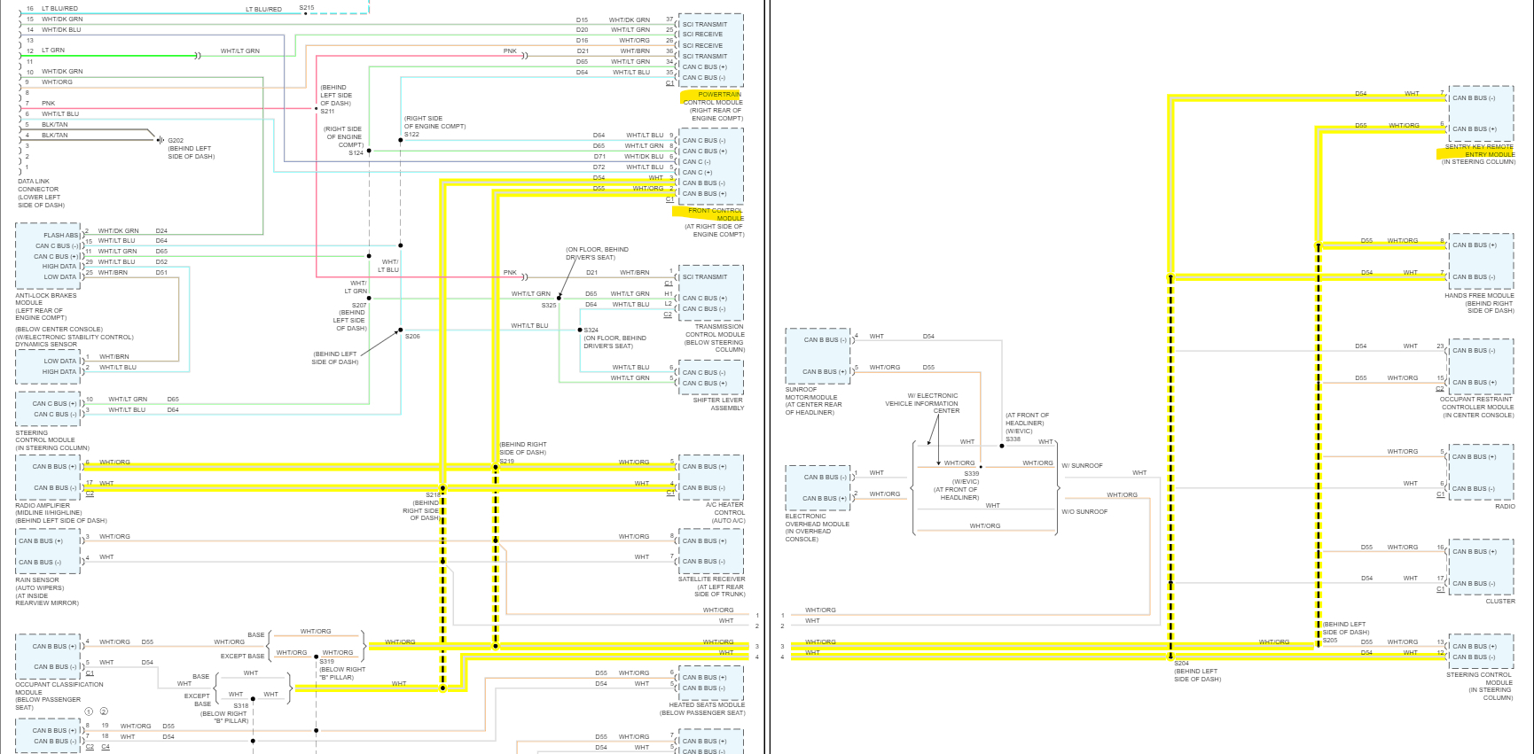
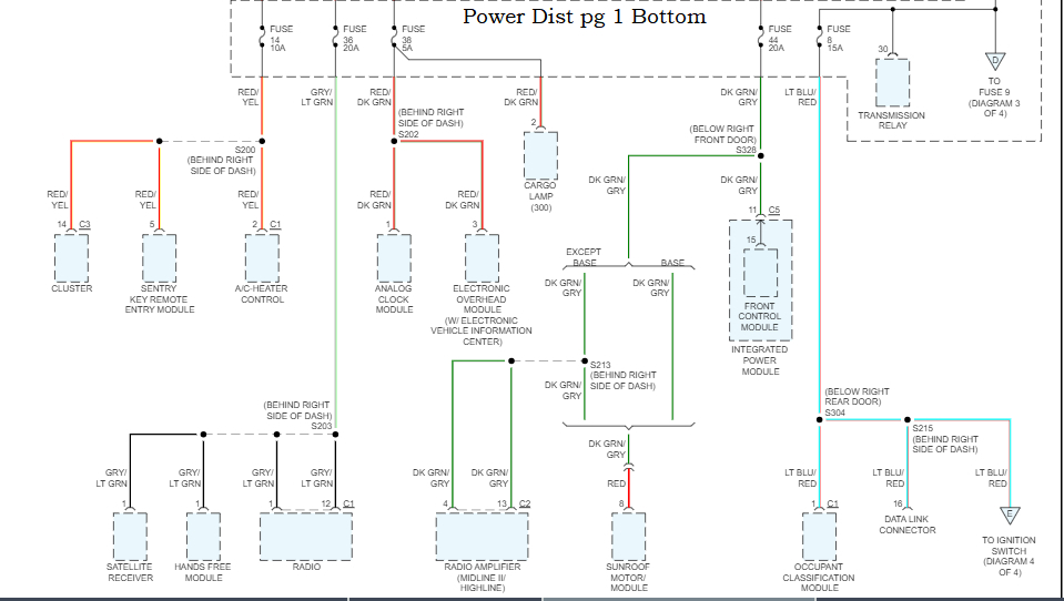
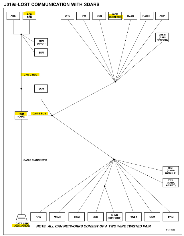
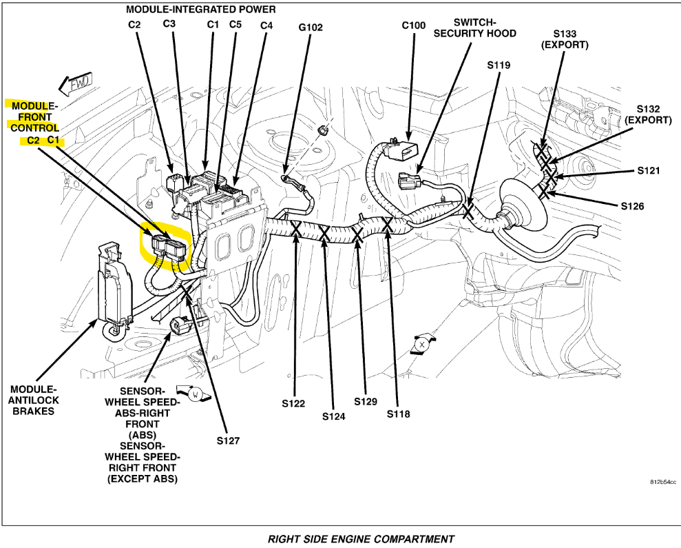
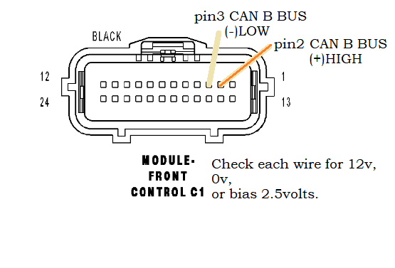
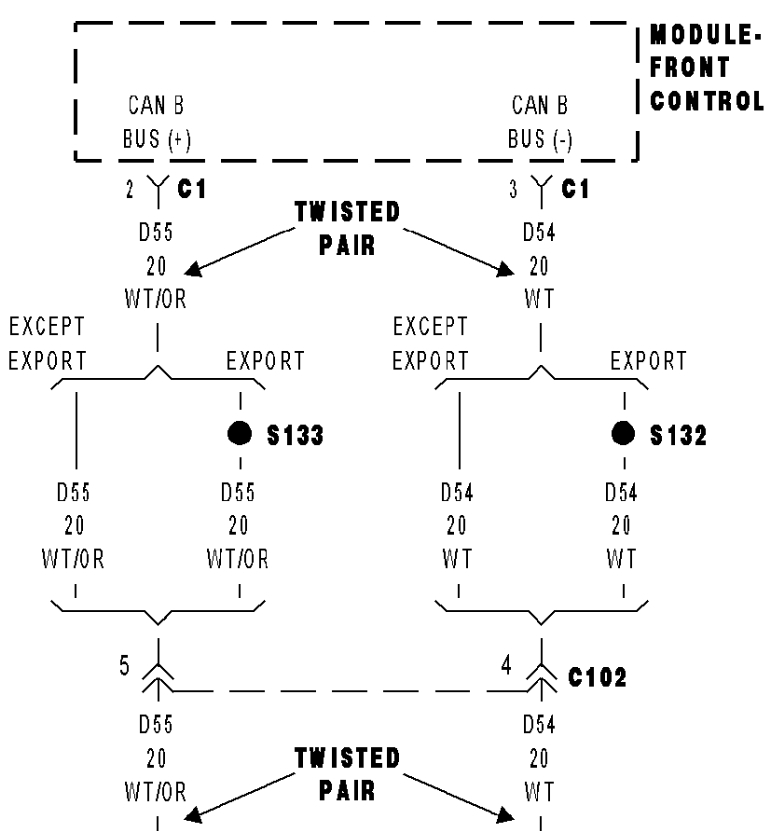
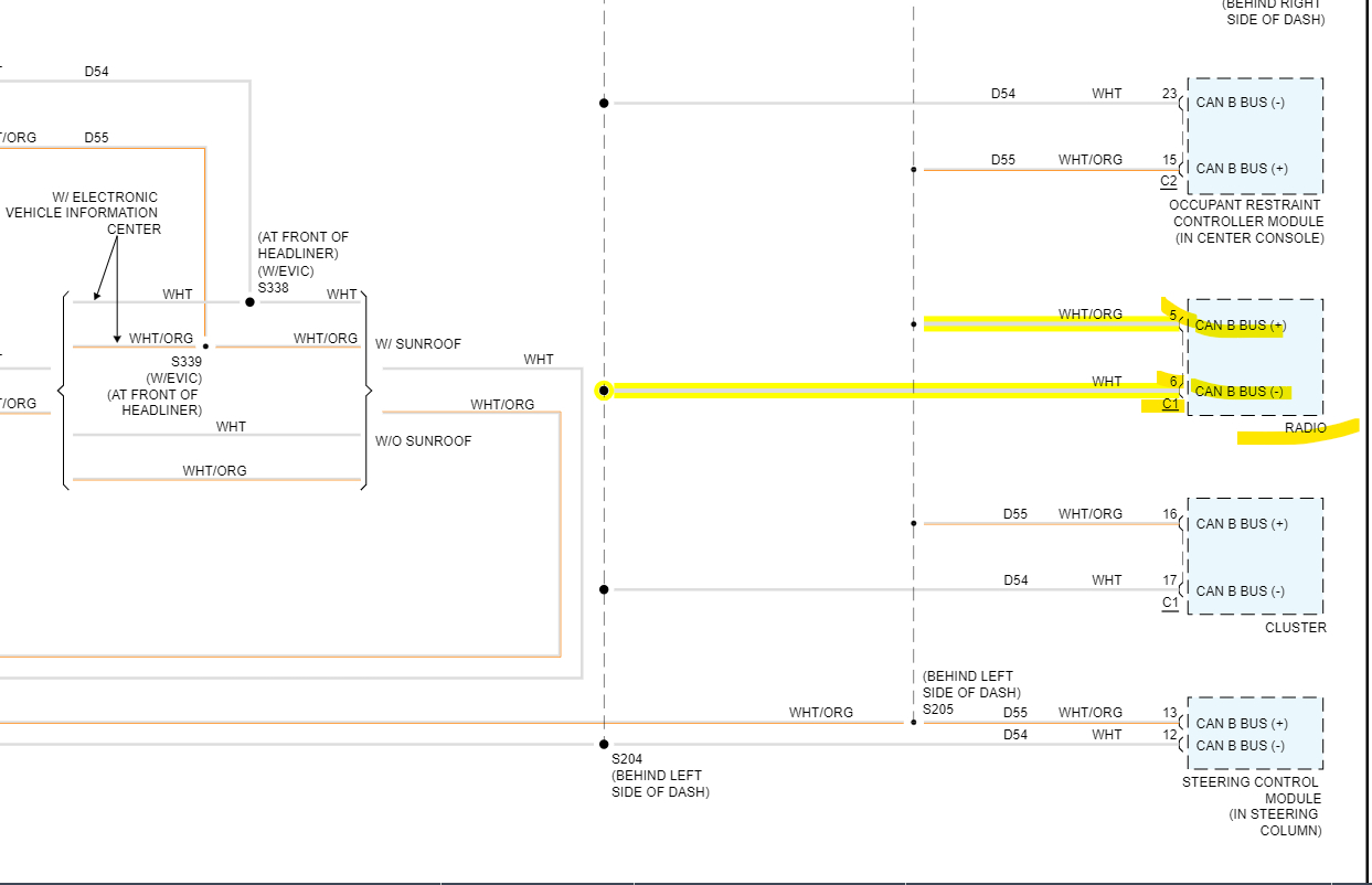
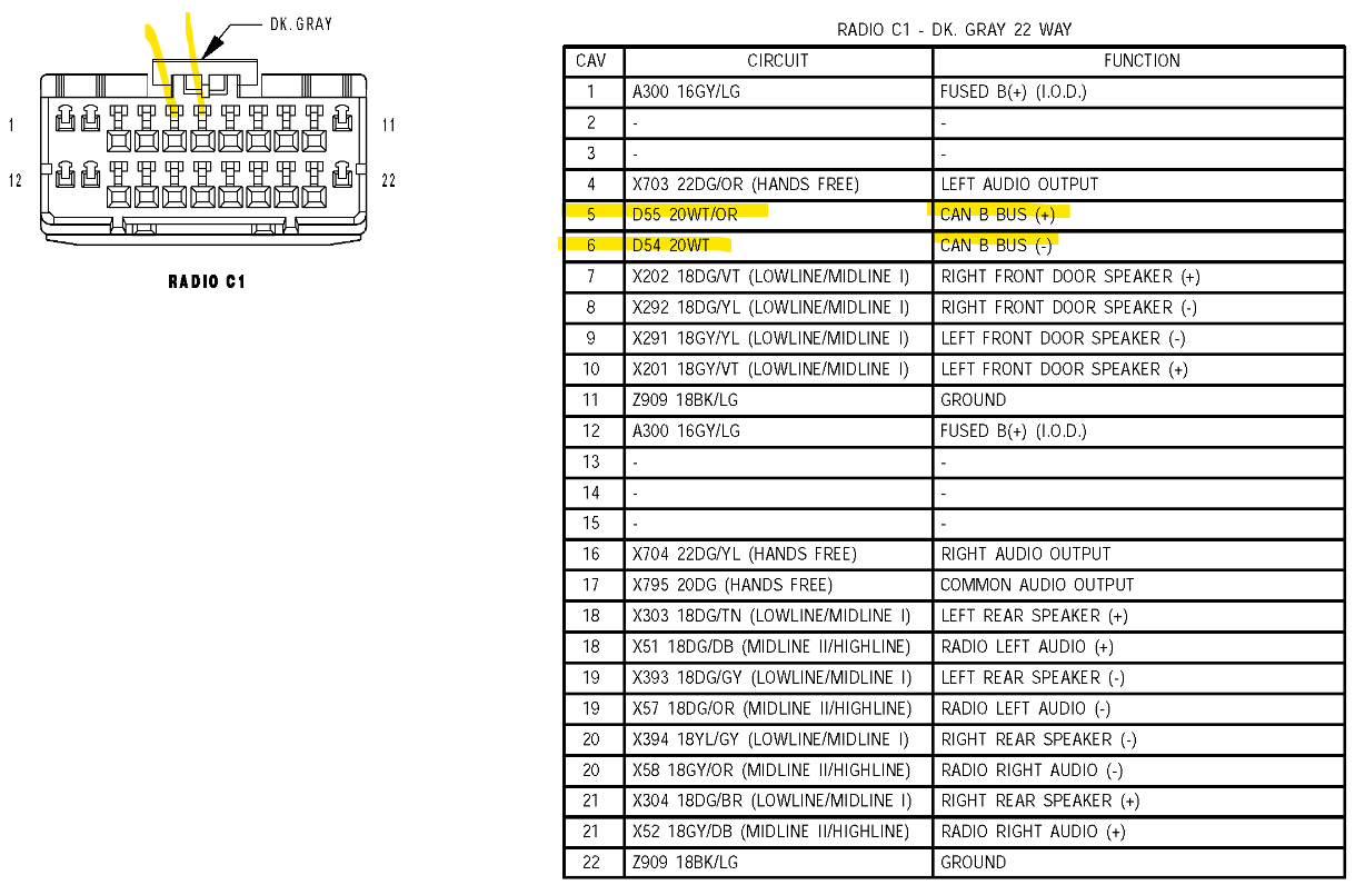
The CAN B doesn't run to the Data Link Connector, only CAN C goes there. All those ECM pin readings are correct. But you're not checking the CAN B, you're only reading the terminating resistors of the CAN C network. Thats why I put the diagrams up for checking the pin 2 and 3 of the Front Control module, connector C1, not the ECM connector. But if you're finding a lot of corroded and loose wires in the dash then keep repairing them, Also if you have the Radio out already you can check the CAN B Bus there, that will be even easier because you have it out already, Ill post the Radio connector pinout, but you should see 2 twisted wires on the Radio connector white/ orange and white, those are the CAN B wires. Check the voltage levels there. If you're finding a lot of corroded wires, with green or white corrosion, this vehicle probably has a water intrusion issue.
Wires that are showing corrosion might need sections to be cut out and replaced. Corrosion from moisture will wick up inside in the wiring insulation, for any connectors that have corrosion you can try some terminal cleaner, Either Deoxit D5 or WD40 Terminal cleaner, auto parts stores carry it. But it has to be an electrical terminal cleaner.

It sounds like someone else has been into the area where you're finding loose connectors and bad wiring. Is this an auction car?
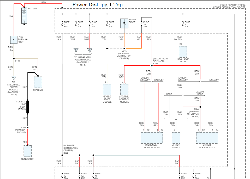
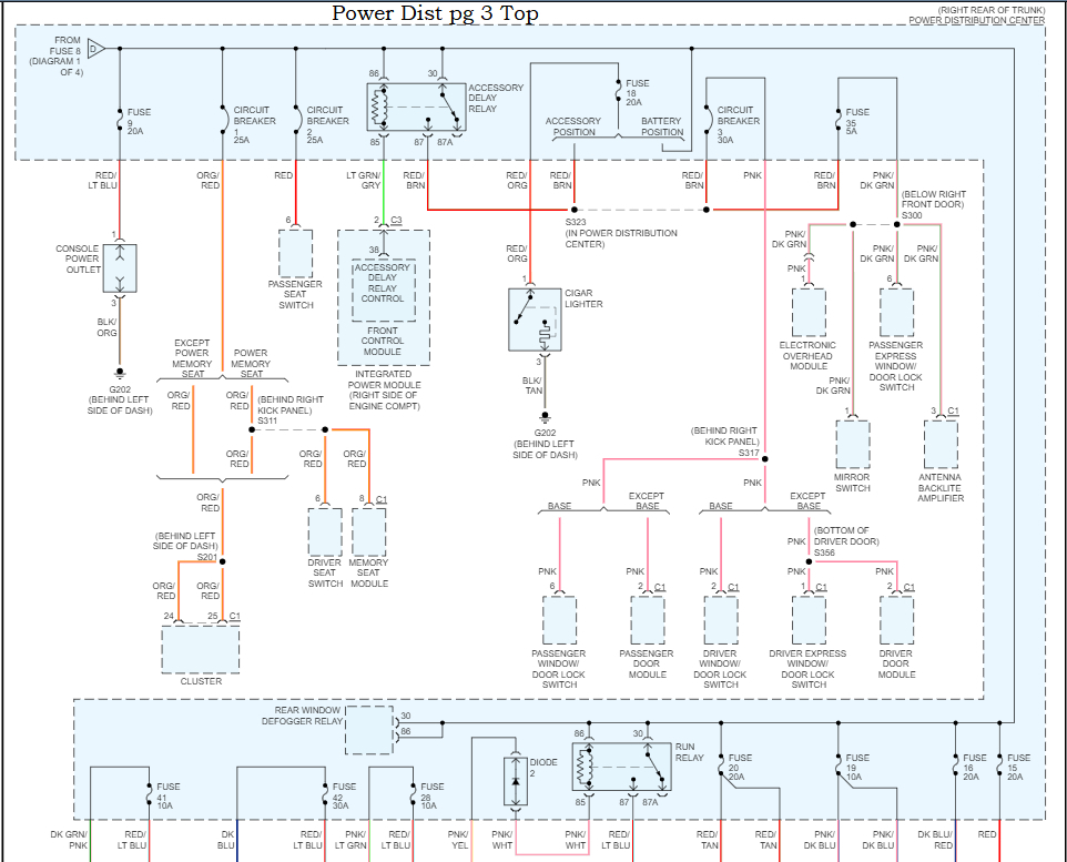
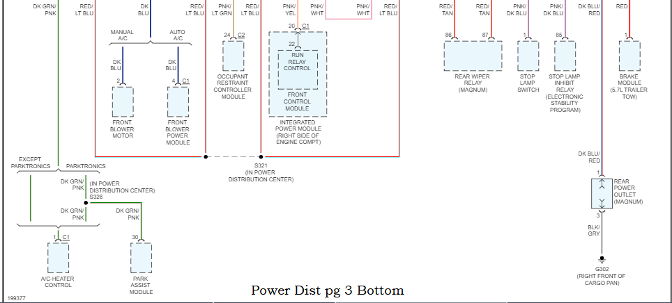
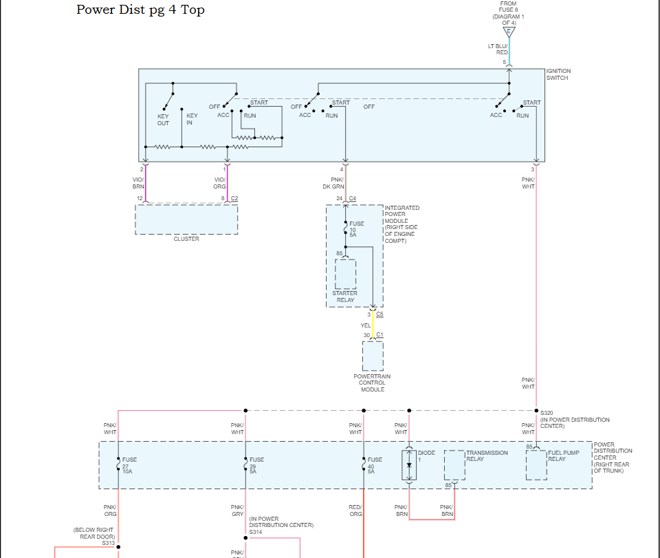
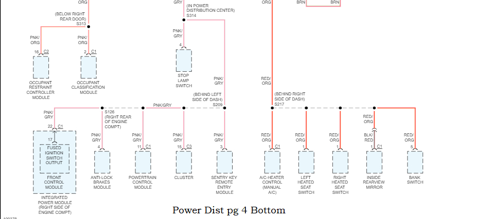
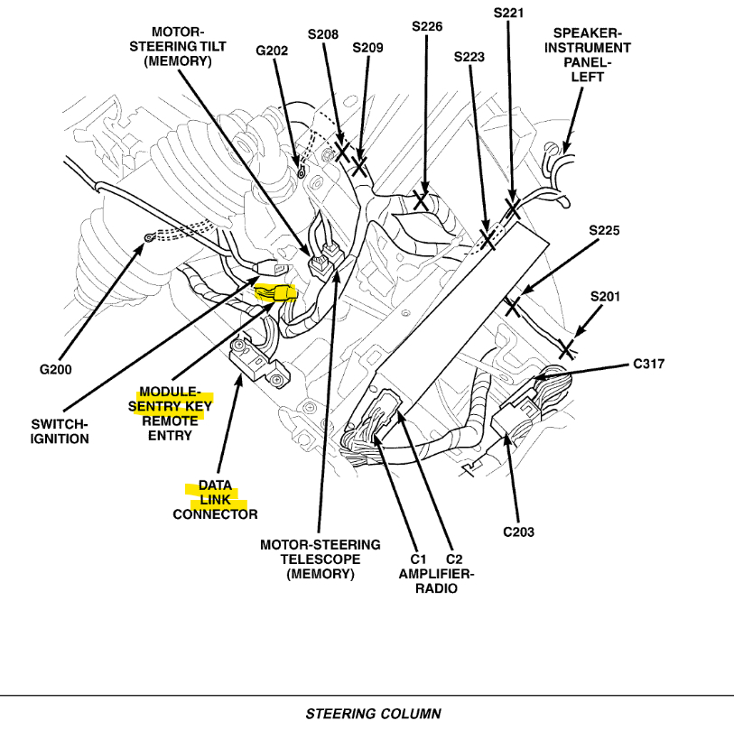
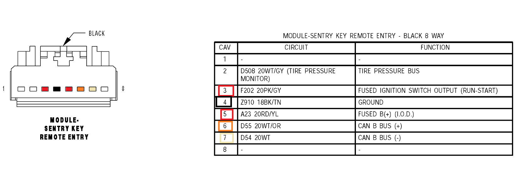
Since you're already into the dash, diagram 3 is the Steering Column and the Sentry Key module, check the connector for power and ground, then check the CAN B for a voltage signal since you have a security system issue. I'm wondering if there is a wiring issue to the Sentry, if its missing power or Ground, or CAN bus messages then the module is not receiving data or outputting data packets, it's not going to allow starting.
Can you look into live engine data or the security system with your scan tool? You should be able to see if there is anything inhibiting starting.

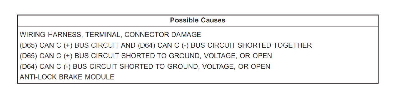
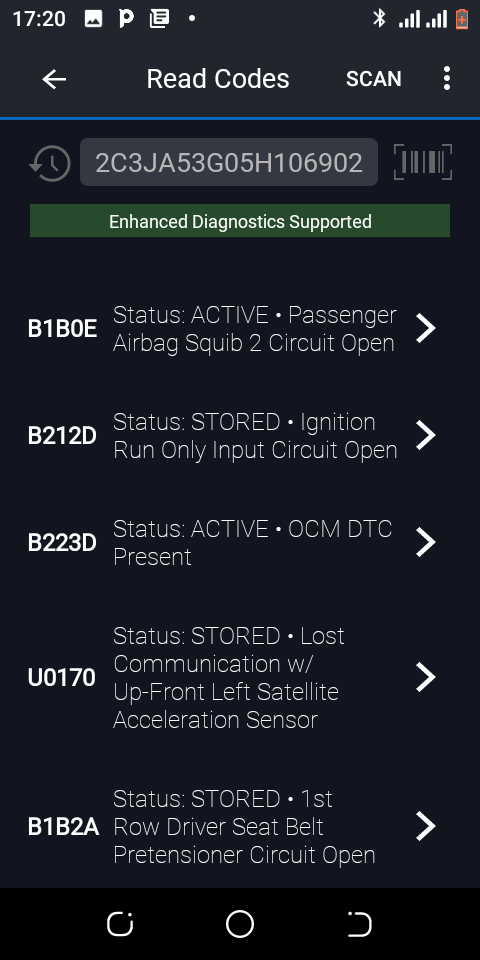
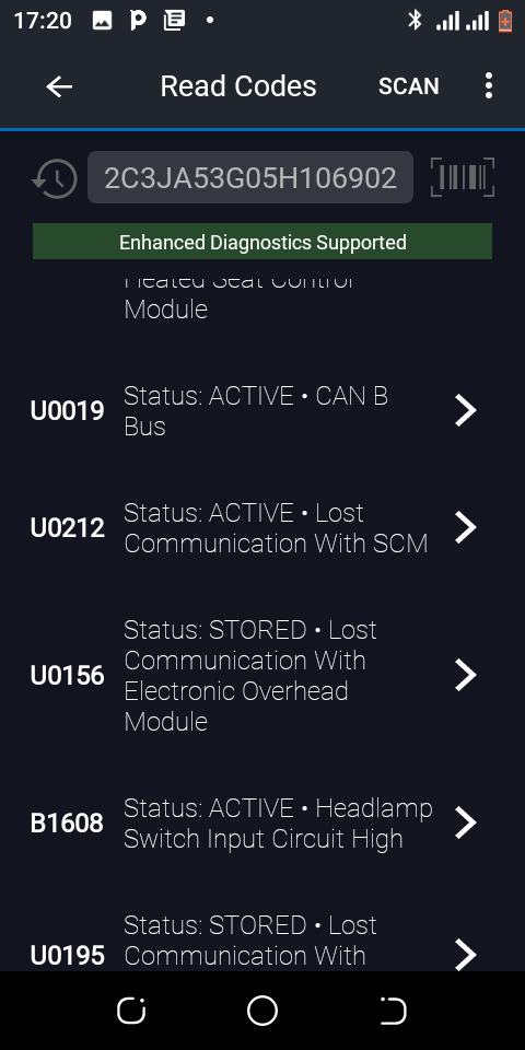
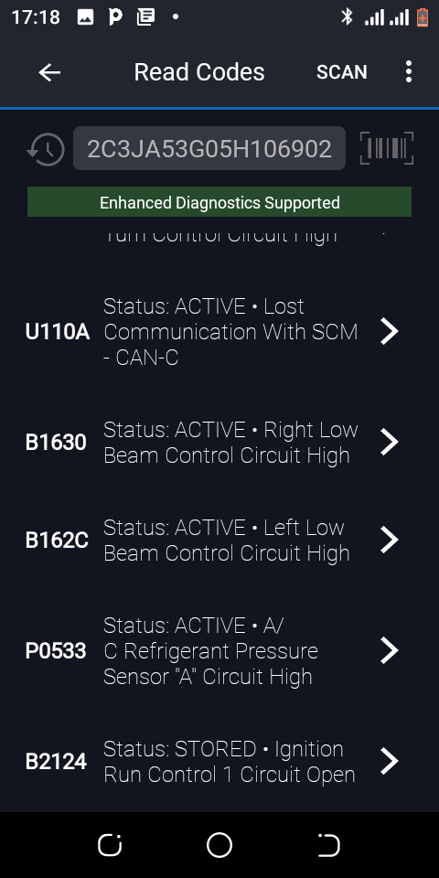
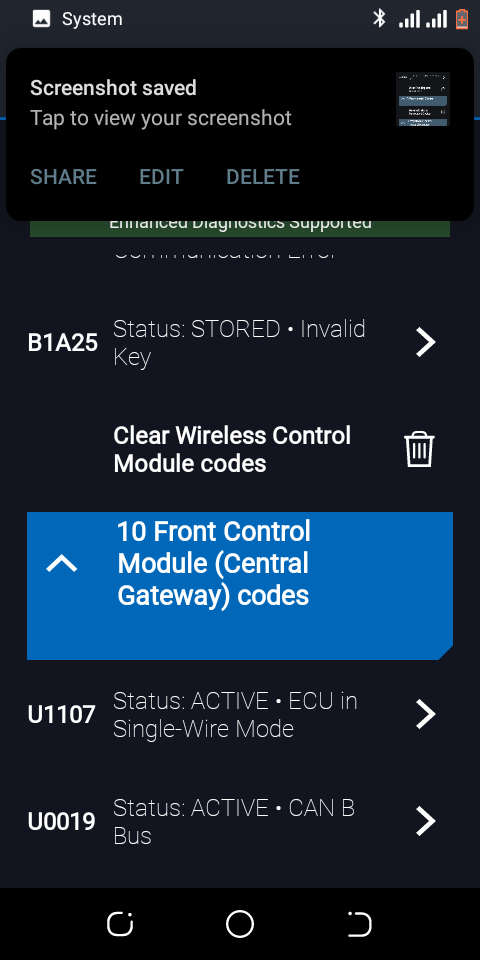
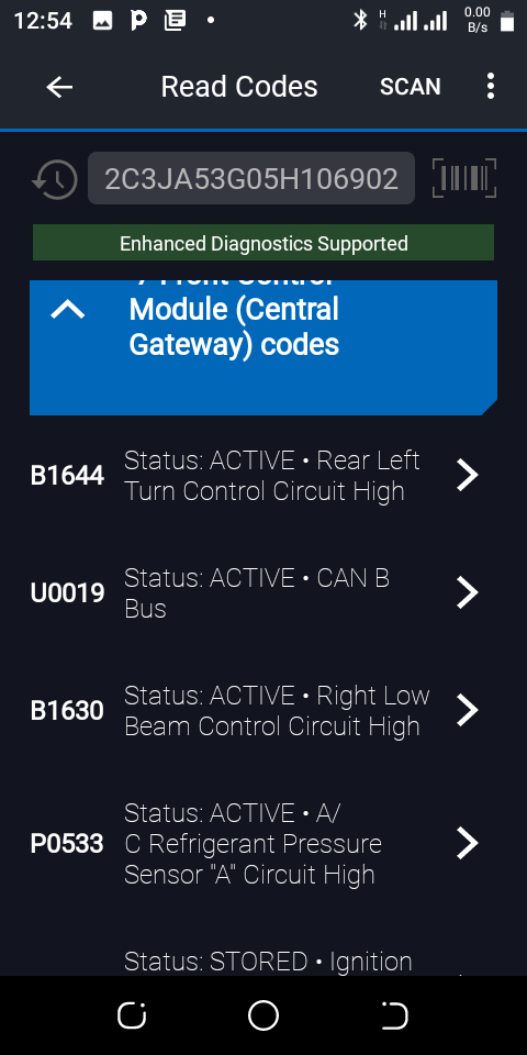
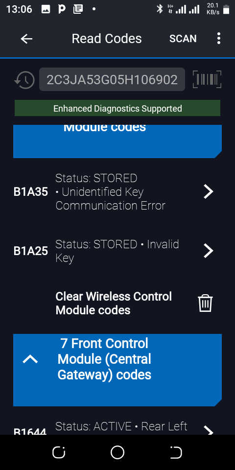
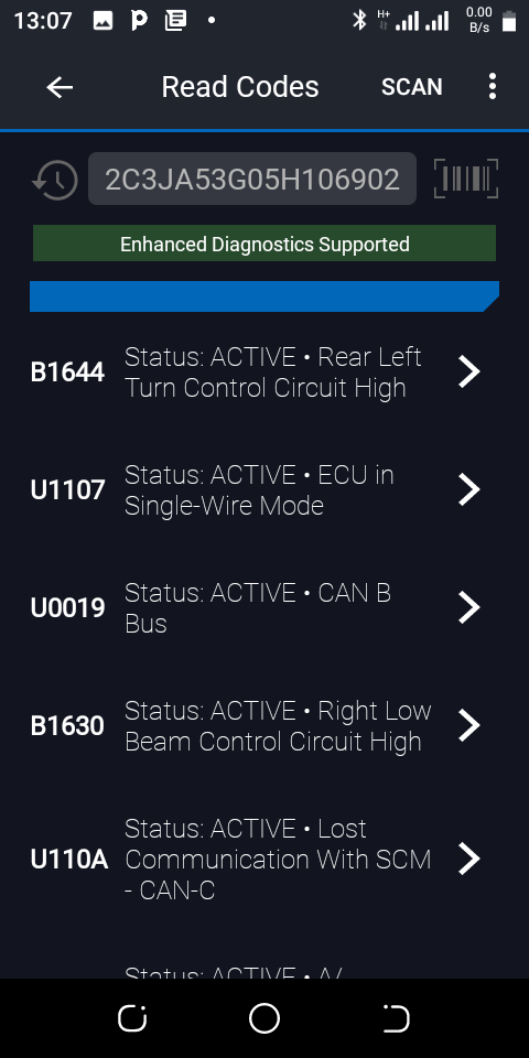
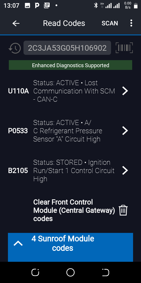
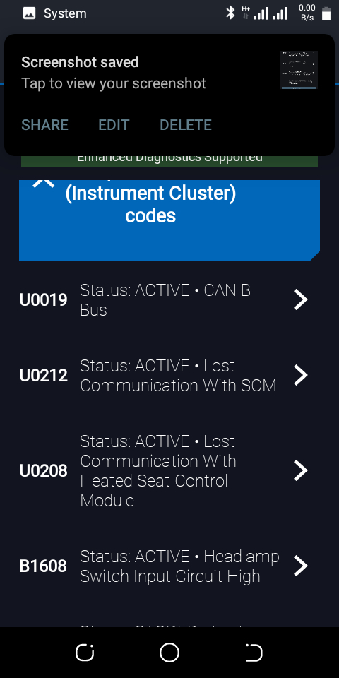
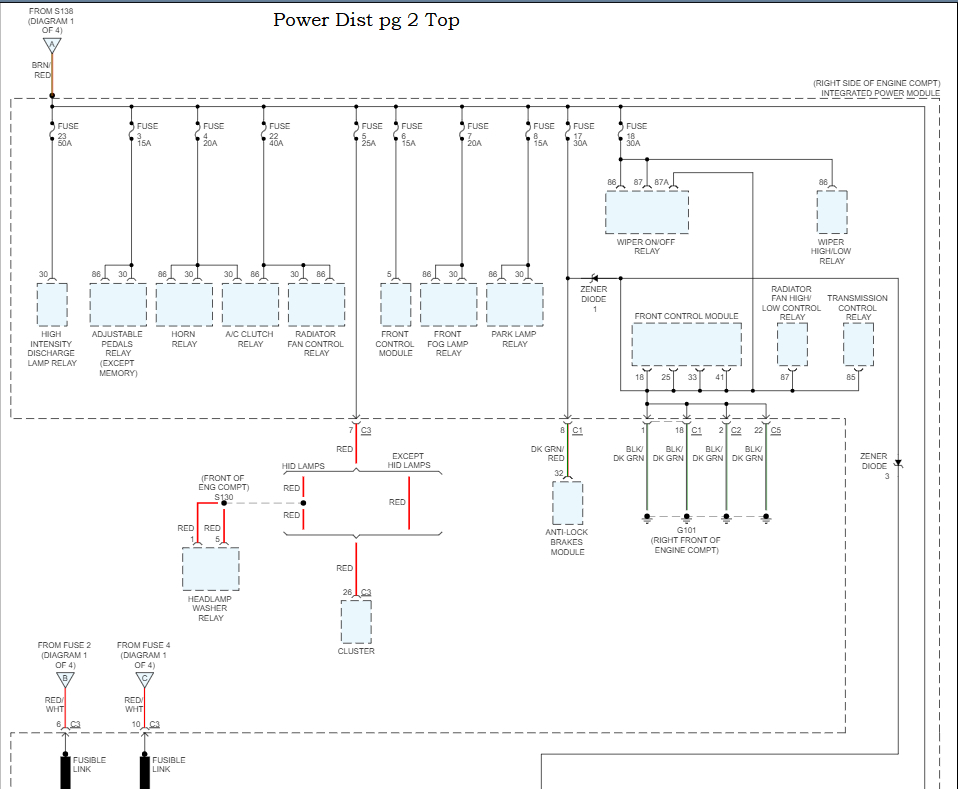
One other thing I just came across is this code B212D Ignition Run Only Input Circuit Open lead me to another code B2124 Ignition Run Control 1 Circuit Open, that code is for power to the Integrated Power Module. There is also this U0019 Status: Active CAN B Bus, so I think there are quite a few wiring problems going on here.
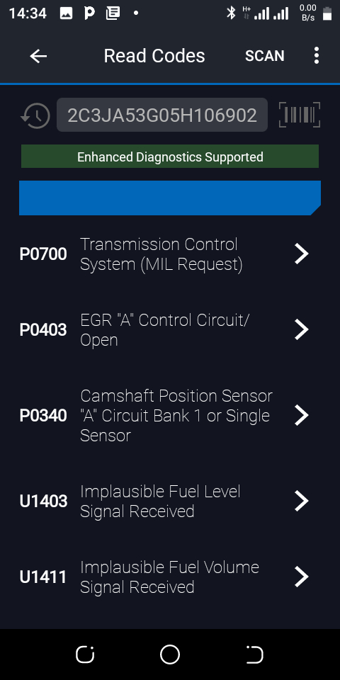
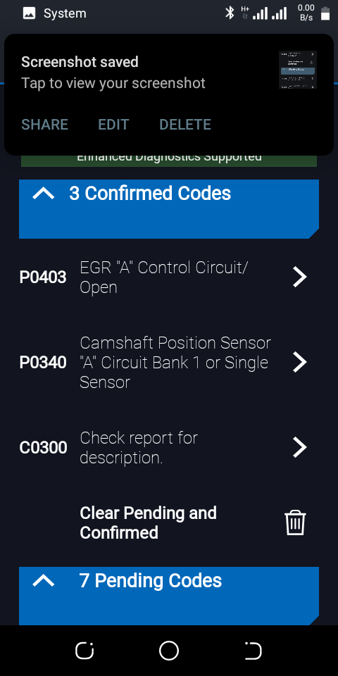
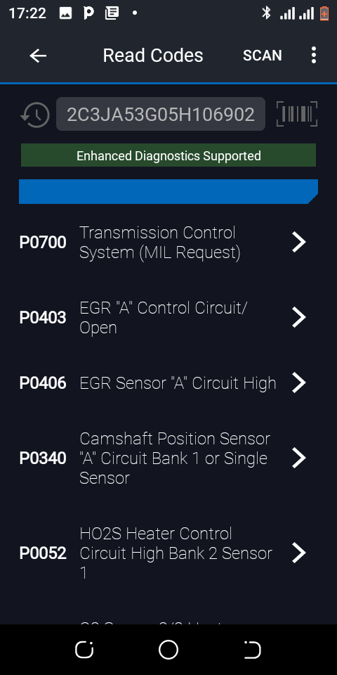
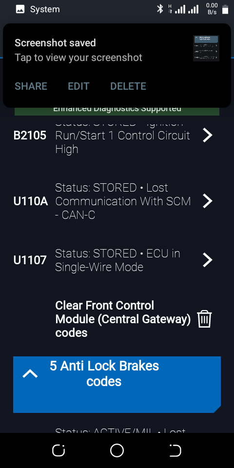
But clear all these codes out, and see what comes back at just key on, because some of these codes might be disabling components. U1107 ECU in Single-Wire mode.
Was this
answer
helpful?
Yes
No
+1
Sunday, August 6th, 2023 AT 1:57 PM
Tiny
DAVID DAVO ESSIEN
  • MEMBER
  • 143 POSTS
In addition, please sir help me. I couldn't locate the Front Control Module C1 connector pin 2 and 3. Please help! Is it located on the driver's side or in the engine compartment?
Please, I'll need your assistance with how I can check for short to ground and power there using my multimeter or perhaps a test light.
Aside from here, please is there anywhere else you want me to check that CAN B network after I have tested this control module C1?
I'll also need the ground wiring. Looking forward to hearing from you.
Was this
answer
helpful?
Yes
No
Sunday, August 6th, 2023 AT 1:58 PM
Tiny
AL514
  • MECHANIC
  • 4,120 POSTS
I just posted a bunch of information, refresh this page and look at my last post, you can check the CAN B at the Radio connector.
Was this
answer
helpful?
Yes
No
+1
Sunday, August 6th, 2023 AT 2:12 PM
Tiny
DAVID DAVO ESSIEN
  • MEMBER
  • 143 POSTS
Thank you for uploading these additional diagrams. What should I be testing for at D55 and D54 in the radio? The module sentry key remote entry in the diagram where's it located in the car? What should I be testing for, please?
Was this
answer
helpful?
Yes
No
Sunday, August 6th, 2023 AT 2:21 PM
Tiny
DAVID DAVO ESSIEN
  • MEMBER
  • 143 POSTS
I saw the radio connector and will be able to locate it again. Please checking the CAN B at the radio connector does it still require locating and testing the control module C1 connector pin 2 and 3? I saw something that looked like the antilock brakes' module under the driver side steering but still couldn't locate the C1 24 pin front control module to proceed with the test. Can you also please give me a guide on how to locate this wire faster?
Was this
answer
helpful?
Yes
No
Sunday, August 6th, 2023 AT 2:41 PM

Please login or register to post a reply.

Sponsored links