Installing a remote car starter

Tiny
RSDOHNER
  • MEMBER
  • 1998 CHEVROLET LUMINA
  • 3.1L
  • V6
  • 2WD
  • AUTOMATIC
  • 170,000 MILES
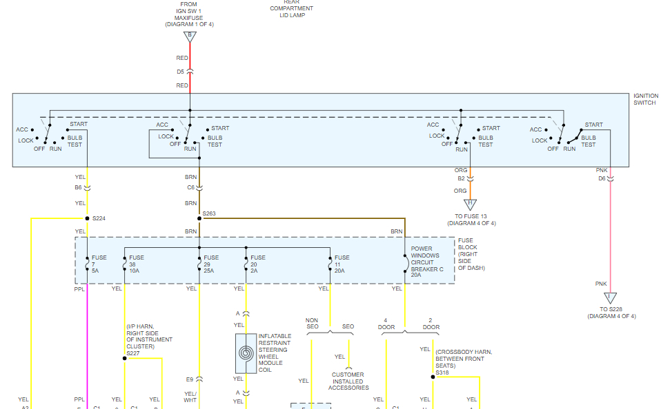
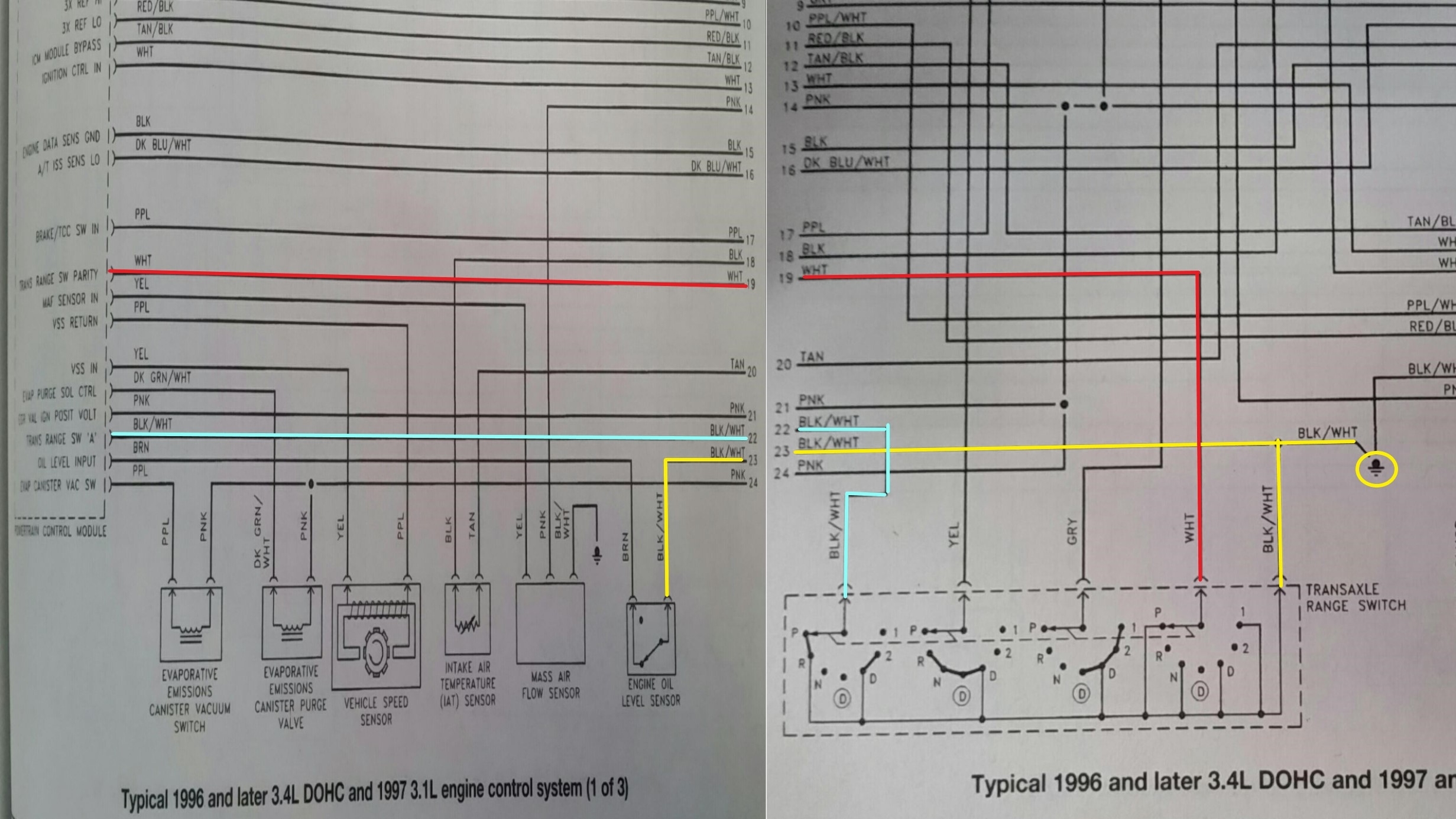
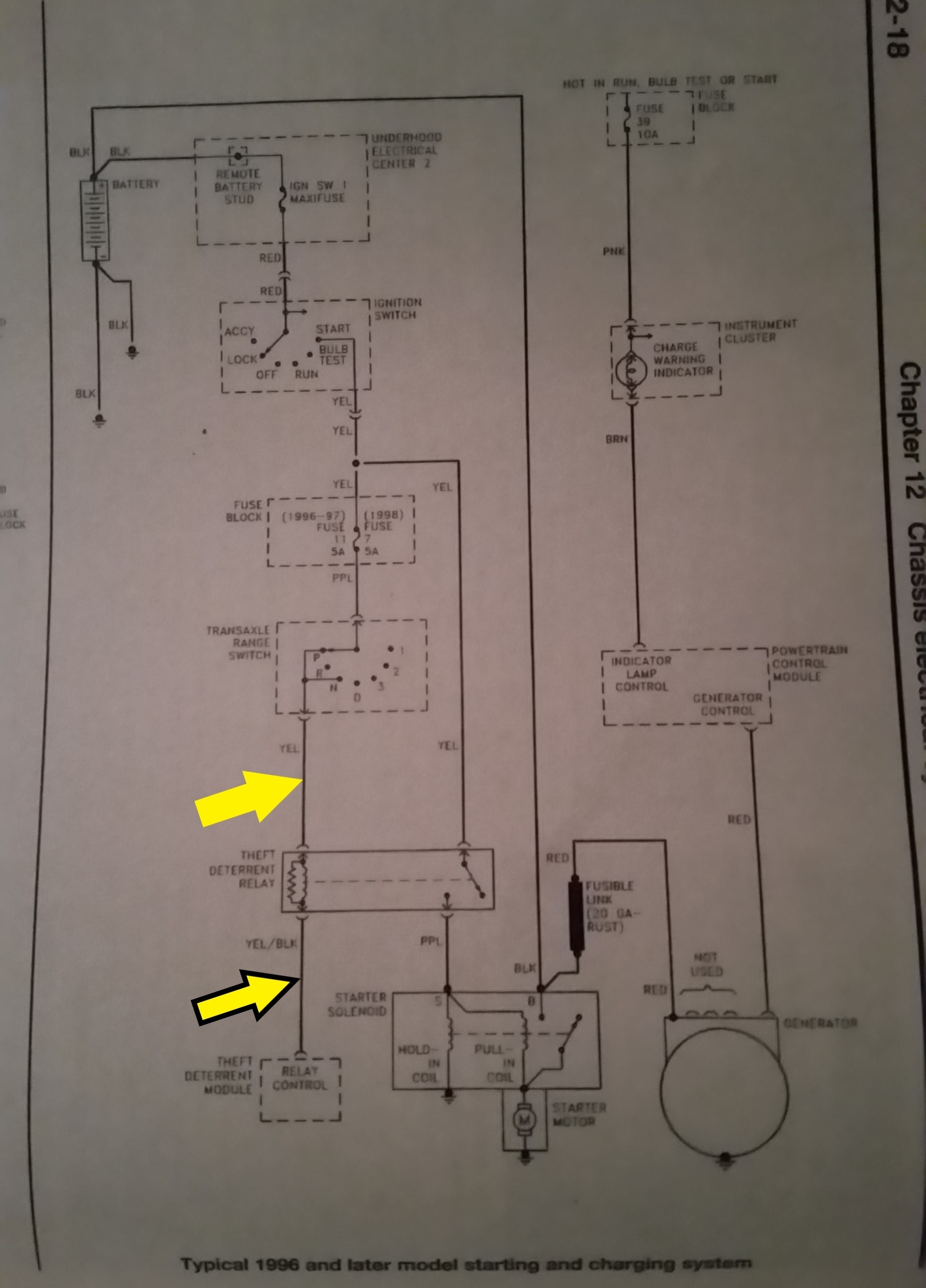
I have been searching the internet for a wiring diagram of the steering column/ ignition switch/driver side dash area of a 1998 Chevrolet Lumina. I really only care to understand what each wire is/the color associated with them/what kind of voltage or signal each wire may have.
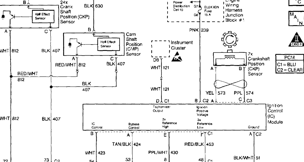
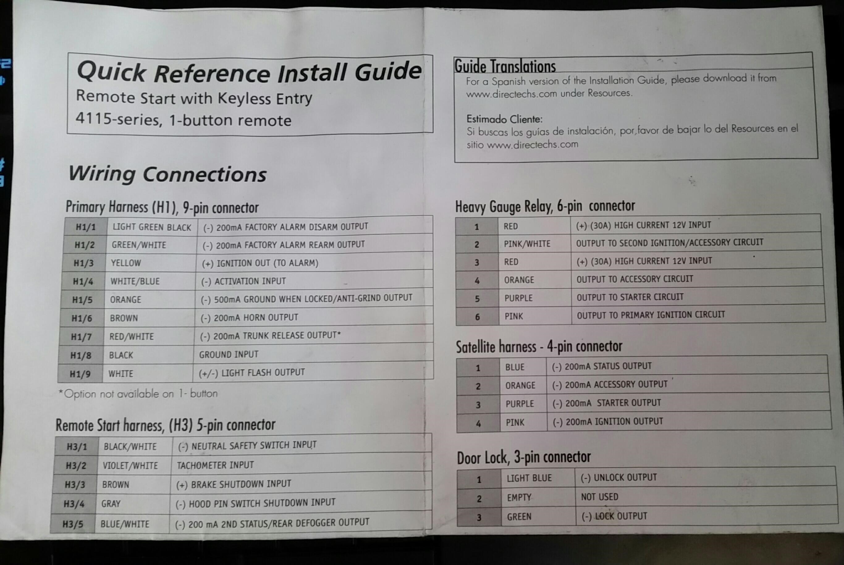
Also, side question. The remote starter can tie into a tachometer signal. This car doesn't have a tachometer so I can't imagine a tachometer signal can be found on this car. Am I right? The remote car starter, I think, uses this signal to know that the engine is running so it will not continue to turn the car over while it is running.
Sunday, December 23rd, 2018 AT 9:23 AM

19 Replies

Tiny
ASEMASTER6371
  • MECHANIC
  • 52,797 POSTS
Good afternoon,

I attached a diagram of the ignition switch for you to review.

As far as a tachometer wire, you would need to go to the ignition module for a tachometer signal. I attached a diagram for you. The white wire is the tachometer signal you need.

Roy

Roy
Was this
answer
helpful?
Yes
No
+1
Sunday, December 23rd, 2018 AT 11:26 AM
Tiny
RSDOHNER
  • MEMBER
  • 10 POSTS
Thanks for your time Roy. I may have further questions. I am trying to install an Avital model 4113 remote starter (one-button, one-way). It comes with a very basic guide that isn't a clean step-by-step instruction manual.
Was this
answer
helpful?
Yes
No
Sunday, December 23rd, 2018 AT 2:27 PM
Tiny
ASEMASTER6371
  • MECHANIC
  • 52,797 POSTS
You are welcome.

We will be here to help.

Roy
Was this
answer
helpful?
Yes
No
Sunday, December 23rd, 2018 AT 3:10 PM
Tiny
RSDOHNER
  • MEMBER
  • 10 POSTS
I have a new question. I have found the tach wire and have moved on. I am now attempting to wire into the " (-) neutral safety switch input " as stated by the quick reference install guide for the remote starter. I also bought a Haynes Repair Manual for this car. There is a transaxle range switch mounted on the transmission; it is connected to the steering column shifter cable, which rotates as you go up and down with the shift lever. The install guide for the remote starter labels the " (-) neutral safety switch input " with a black/white color code. The wire is black with a white stripe running the length of the wire. Looking at the schematics in the Haynes Repair Manual, the transaxle range switch has a black/white wire coming from the PCM, which I colored blue in the attached image. There is also another black/white wire on the other end of the trans range switch, which is tied to ground and is colored yellow. Tying into the "yellow-colored" wire doesn't make sense to me because then how would the remote starter module know the vehicle is in Park or Neutral. So this logic tells me I need to be "up-stream" of the switch. Looking at the schematics of the switch at each segment, it seems none of the segments only have a closed circuit in park or neutral. The furthest right segment seems to make the most sense to me, but not entirely, as there is also continuity in "D" and "1" positions. For this reason, though, I feel maybe I want to tie into the red-colored wire because at least that way the circuit would be closed in Park and Neutral, and not in reverse.

I will also attach the install guide for the starter as reference. Any advice would be helpful. I talked to my dad, and we think it should be safe to tie into the black/white wire that is upstream (blue-colored) wire. I still think the red-colored would be the best. I want to hear another experienced opinion before I move forward. Thanks for your time.
Was this
answer
helpful?
Yes
No
Saturday, December 29th, 2018 AT 1:42 PM
Tiny
ASEMASTER6371
  • MECHANIC
  • 52,797 POSTS
I agree with the red wire as it only sends a signal to the pcm in park and neutral.

What do you have the 5 or 9 pin connector?

Roy
Was this
answer
helpful?
Yes
No
Saturday, December 29th, 2018 AT 1:58 PM
Tiny
RSDOHNER
  • MEMBER
  • 10 POSTS
The odd thing is that one of the two connectors on the transaxle range switch, which has the corresponding colors and order per the schematic of black/white, white, grey, and yellow, is only a 4 pin connector. The schematic made me think I was looking for a 5 pin with the addition of another black/white wire. I was thinking maybe because it's ground that it grounds through the transmission and engine block.

I attached some images from the web of what I am talking about. I am now attempting to test continuity at the PCM connector in order to find the best place to tie into the wiring, since right on top of the transmission is difficult to work around.

I'm going to take a quick look, again, at the transaxle range switch to make sure it is the same as in the images.
Was this
answer
helpful?
Yes
No
Saturday, December 29th, 2018 AT 2:08 PM
Tiny
ASEMASTER6371
  • MECHANIC
  • 52,797 POSTS
Okay, the same question applies.

I still think it is the red highlighted wire.

Roy
Was this
answer
helpful?
Yes
No
Saturday, December 29th, 2018 AT 2:12 PM
Tiny
RSDOHNER
  • MEMBER
  • 10 POSTS
What do you mean "the same question applies"? Still asking if I have a 5 or 9 pin connector? If so, are you referring to the connectors to the trans-axle range switch, because then the answer is 4 or 7, not 5 or 9.

Did you mean same answer? Referring to the red wire as the best choice.
Was this
answer
helpful?
Yes
No
Saturday, December 29th, 2018 AT 2:18 PM
Tiny
ASEMASTER6371
  • MECHANIC
  • 52,797 POSTS
Yes. The 4 pin connector is most likely it. There should be a provision for a fifth wire but the cavity may be empty.

Roy
Was this
answer
helpful?
Yes
No
Saturday, December 29th, 2018 AT 2:27 PM
Tiny
RSDOHNER
  • MEMBER
  • 10 POSTS
Okay, thanks Roy. I'll give it a go. First, I'll test continuity with this white wire from the trans-axle range switch connector to the PCM. Then I'll test from PCM, where I found continuity, to ground as I go through the gears to confirm that we at least have continuity in park and neutral. If you'd like I'll let you know how it goes. I've appreciated the help.
Was this
answer
helpful?
Yes
No
Saturday, December 29th, 2018 AT 2:35 PM
Tiny
ASEMASTER6371
  • MECHANIC
  • 52,797 POSTS
Sure, keep us updated.

Always glad to help.

Roy
Was this
answer
helpful?
Yes
No
Saturday, December 29th, 2018 AT 2:40 PM
Tiny
RSDOHNER
  • MEMBER
  • 10 POSTS
Found the pins in the PCM connector for the white (colored red in schematic) and the black/white (colored blue in schematic). I tested for continuity from ground with the trans-axle range switch connector plugged in. Sure enough, I was getting continuity in the exact positions as shown in the schematic. I'll have to pick that white wire and go with it. Once I get it wired in I'll have to test the remote start with it in the other gears. I have a feeling I will just have to let my mother know to never start it from any gear but park, which is common sense anyway and the only practical way it will be started.
Was this
answer
helpful?
Yes
No
Saturday, December 29th, 2018 AT 4:17 PM
Tiny
ASEMASTER6371
  • MECHANIC
  • 52,797 POSTS
Sounds like plan.

Roy
Was this
answer
helpful?
Yes
No
Saturday, December 29th, 2018 AT 5:01 PM
Tiny
RSDOHNER
  • MEMBER
  • 10 POSTS
So I found this schematic for the starting/charging system side of the trans-axle range switch. This part of the switch makes more sense to me with the connection happening in only park and neutral. The installation guide says " (-) neutral safety switch input " I worry that if I wire at either the yellow or yellow/black wire, that I have labeled in the attached photo, I would be applying 12 V to the "-" input called by the guide. I'm curious your thoughts? Do you think this would be harmful to the remote start module?

I also feel there's more to the neutral safety switch than what is provided to me with this service manual. I have accountability of the 4 pin connector and only two of the 7 pin connector. I wonder if there's a better place to wire into.
Was this
answer
helpful?
Yes
No
Tuesday, January 1st, 2019 AT 3:35 PM
Tiny
ASEMASTER6371
  • MECHANIC
  • 52,797 POSTS
The wire that is at the big yellow wire is the one I would use.

Roy
Was this
answer
helpful?
Yes
No
Tuesday, January 1st, 2019 AT 3:55 PM
Tiny
RSDOHNER
  • MEMBER
  • 10 POSTS
So the last few days I've wired into some luxury features of the remote car starter:

1. The parking light wiring at the switch so that lights blink when the car is remote started.
2. The horn so the horn sounds when starting.
3. The rear window defogger so that it comes on when the car is remote started.

These were the last few things I wanted to wire in that I believe were needed/wanted. I plugged in all the connectors and began the installation programming process. I believe I have successfully taught the remote start module the tachometer signal. The next step was to attempt to play around with the programming options. I was able to see that the LED on the module was responding as it should and that the horn was also sounding in sync with the LED blinks. I was disappointed as I thought the parking lights would also blink as well. At this stage I was feeling pretty good. I followed the guide to allow the module to mate with the remotes. The module responded as it should so successful remote recognition seemed to have taken place. Then to me, the next step was to attempt a remote start. I came to find that the LED on the remote flashed but the module and car did not respond at all. I learned through the directechs. Com website that I may need a resistor to override anti-theft (I attached a screenshot).

Would you agree I need to find a resistor to match the key's resistance in the chip? I feel the neutral safety switch wiring I did might not be right either, since I was concerned about the 12V presence where it calls for a (-) input. I wired into the solid yellow arrow (top) in the attached schematic. I feel because it is in circuitry with the anti theft module it is looking for a specific voltage signal to close that relay which engages the starter solenoid. Maybe I should attempt to wire into the yellow/black wire below it. That kind of makes sense to me because the module would ground out the voltage to the other side of the relay, which would cause current to flow through the magnetic coil of the relay and close its switch. Thoughts?

FYI the car so far starts and runs normally with the key.
Was this
answer
helpful?
Yes
No
Friday, January 4th, 2019 AT 9:53 AM
Tiny
ASEMASTER6371
  • MECHANIC
  • 52,797 POSTS
I would measure the resistance of the key and use the resistor at the bottom of the column.

Roy
Was this
answer
helpful?
Yes
No
Friday, January 4th, 2019 AT 10:13 AM
Tiny
RSDOHNER
  • MEMBER
  • 10 POSTS
So after I've watched some videos, people were saying to just ground the neutral safety switch input wire. I gave it a go and the car started remotely! I also tested to see if it would start in gear and it doesn't. It only starts in park and neutral as we would hope, but I think it's not due to the module. I think it acts this way because the car is smart enough to not let itself be started by the module. The module attempts three times to start, but the car won't let it do it. Good enough for me, but something to keep in mind. Thanks again for help.
Was this
answer
helpful?
Yes
No
Saturday, January 5th, 2019 AT 9:15 AM
Tiny
ASEMASTER6371
  • MECHANIC
  • 52,797 POSTS
Glad to hear it works.

Roy
Was this
answer
helpful?
Yes
No
Saturday, January 5th, 2019 AT 9:37 AM

Please login or register to post a reply.

Sponsored links