I have an electrical short, now what?

Tiny
FONSECA.SARAH1
  • MEMBER
  • 2002 CHEVROLET IMPALA
  • 3.8L
  • V6
  • 2WD
  • AUTOMATIC
  • 141,000 MILES
I found a video online where you connect a test light to the battery and pull-out fuses one by one and with that found that two separate fuses on the passenger side fuse block made the test light go out. The cigarette lighter fuse and the DIC/RKE/HVAC fuse. I replaced the cigarette lighter socket and repaired that one. But I don't know how to figure out where the short is. I have done a lot of reading online, I have a wire tracing device. Not a power probe but I think I get how it works and how to use it but everything I read online is like directions on what to do once you find the suspected culprit. I can't for the life of me figure out how to read a wiring diagram and interpret it into anything useful. The cigarette lighter was easy enough because it's one thing. But the driver information center, remote keyless entry and HVAC are not, so just kind of wondering if you have any insight on how to go about this mission?

Please and thank you.
Thursday, May 18th, 2023 AT 3:00 PM

7 Replies

Tiny
CARADIODOC
  • MECHANIC
  • 33,754 POSTS
There's a couple of problems with your procedure. If you're removing a battery cable, then connecting a test light between the battery post and the cable clamp, test lights require a good amount of current to light up. Unless specified otherwise by the manufacturer, (Cadillac, for one), the industry standard is no more than 35 milliamps, (0.035 amp) is allowed for all the computer memories. The typical test light draws closer to 500 milliamps, or half an amp, and will need roughly half of that to make a visible glow in the filament. You can have an excessive drain and never see it in the test light. About the only thing it's good for is if there's a direct short, and that would be blowing a fuse. The better alternative is to use a digital volt / amp meter, but even that poses a problem. Luckily you have us to walk you through it.

The next problem is by around the mid to late '90s, most vehicles have some computers that remain awake for up to 20 minutes after the ignition switch is turned off. You have to wait for them to time out before any current drain readings are valid. The additional precaution is anything you do to break the circuit, even for an instant, will wake those computers up again for another 20 minutes. That includes momentarily disconnecting the amp meter, and it includes switching the range on the meter to get more accuracy.

First of all, so I'm clear, you do not have a short, meaning a fuse is blowing, is that correct? If a fuse is blowing, I have a trick for working with that type of problem. If you simply have something draining the battery overnight, this amp meter procedure will work.

You can start by looking at this article:

https://www.2carpros.com/articles/how-to-use-a-voltmeter

They're using an auto-ranging meter which is an expensive feature you don't need. Harbor Freight Tools has a perfectly fine meter for $7.00. You can also find them at Walmart or any hardware store. I can help you set it up.

Most of these meters have an internal two-amp fuse for the Amps function. While waiting the 20 minutes for the computers to go to sleep mode, they can draw a total of up to three amps. That would blow the meter's fuse, so it has to be bypassed during that waiting period. The other problem is all meters use a rotary switch that's called a "break-before-make" design. That means as you turn the dial to a different range, it breaks the internal connection to one range first, then, as you continue to turn the knob, it makes the connection to the next range. That momentary break in the circuit is enough to wake up the computers, and blow the meter's fuse. It's simply a matter of bypassing the meter again each time you want to change to a different range.

Almost all of these inexpensive meters also have you move the positive probe to a special third jack for only the highest amps range. That will get us started, but when the current reading is rather low, you want to switch to a lower range to get more places after the decimal point to get more accuracy. The first lower range is to place the red positive probe back in the "common" jack. That means unplugging it to move it, and that means breaking the circuit again. This is another time the meter needs to be bypassed, and that simply requires a small jumper wire that is connected only while you're moving the probe to a different jack, or when switching ranges.

I'm beginning to confuse myself now, so I'm going to put together a procedure with drawings tonight to help walk you through this. In the meantime, find an inexpensive digital volt / ohm / amp meter, and a jumper wire. Any piece of wire will work, but that can lead to frustration. The better alternative is to look for a set of jumper wires at Harbor Freight Tools. They have a pack of ten or 12 for around $4.00. I'm going to also suggest a larger vise-grip pliers to hold one probe to the battery's post. It's almost impossible to connect anything to the battery otherwise.
Was this
answer
helpful?
Yes
No
Thursday, May 18th, 2023 AT 4:00 PM
Tiny
CARADIODOC
  • MECHANIC
  • 33,754 POSTS
Okay, here's what I put together last night. I tried to start out as basic as possible so anyone with no knowledge of electrical circuits can get the information we need. With the help of your suggestions, I'll fine tune this later. If you're comfortable using the voltmeter, you can skip to Part 2.

Part 1 Measuring Voltage

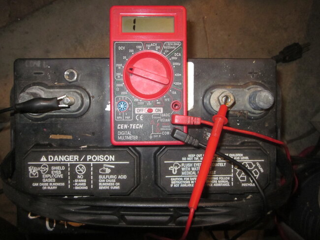
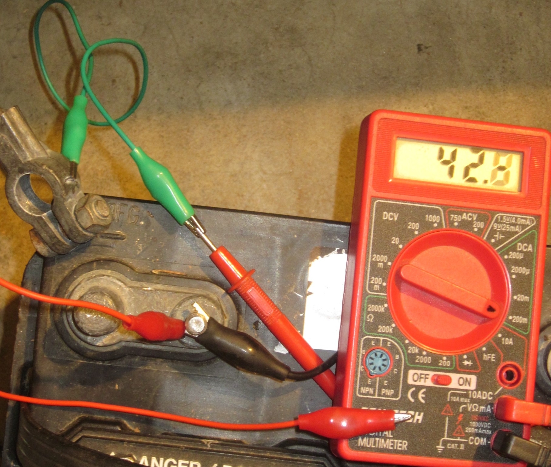
Photo 1 shows the inexpensive digital meter from Harbor Freight Tools. Home Depot has an identical one in yellow. These can also be found at Walmart and any hardware store.

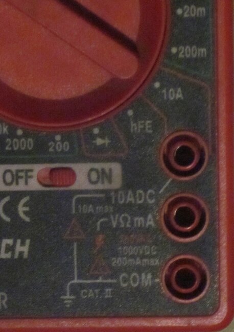
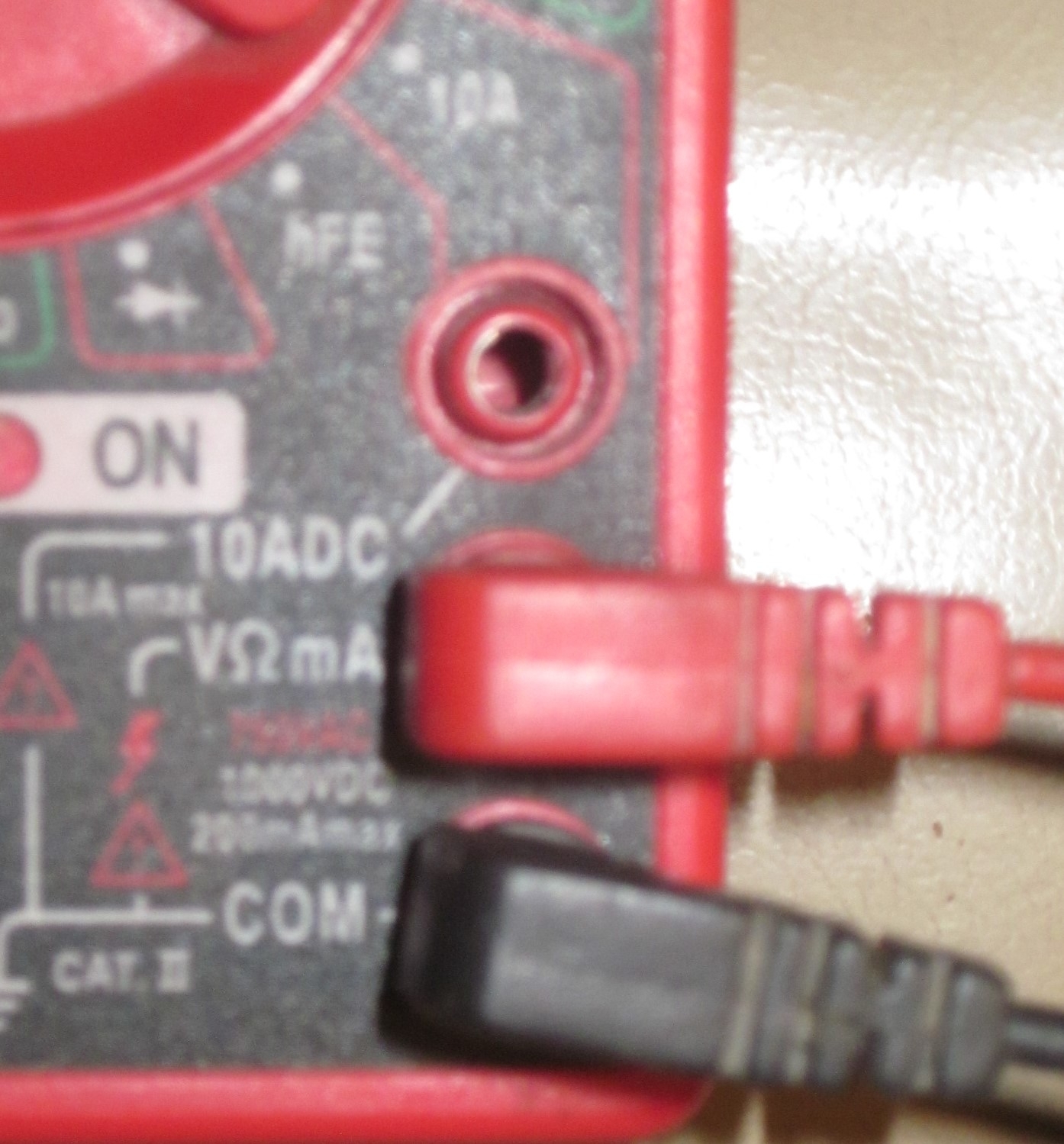
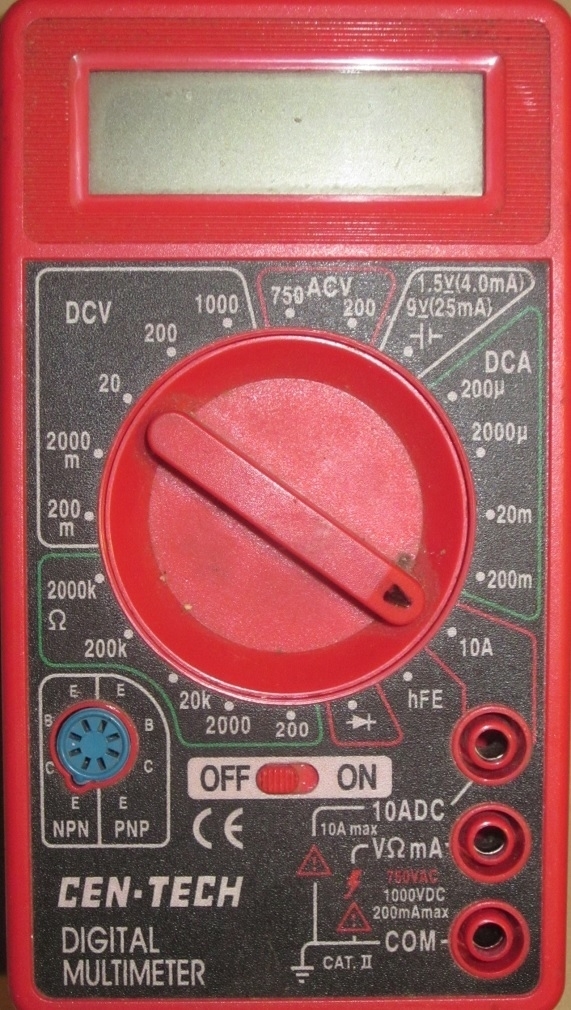
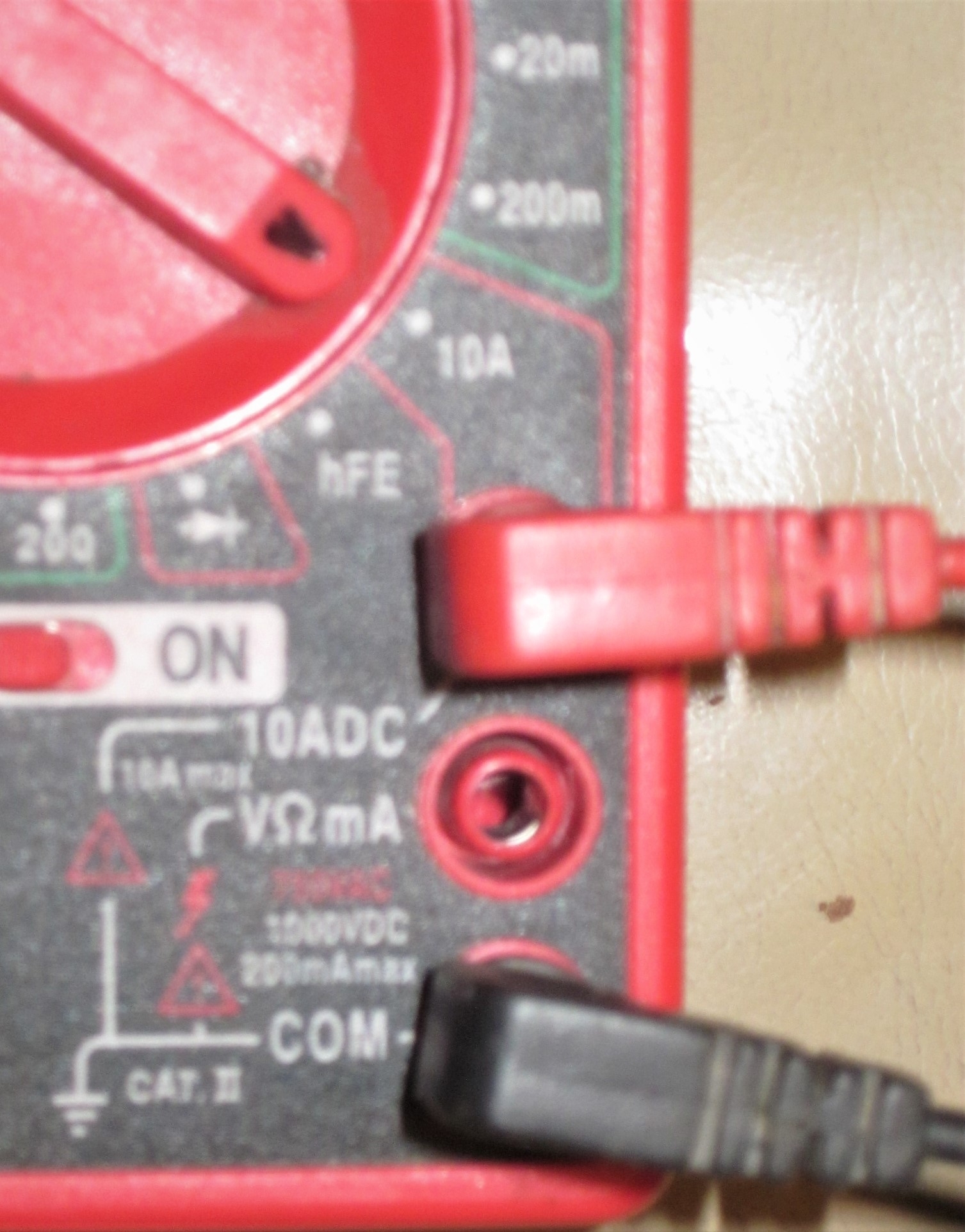
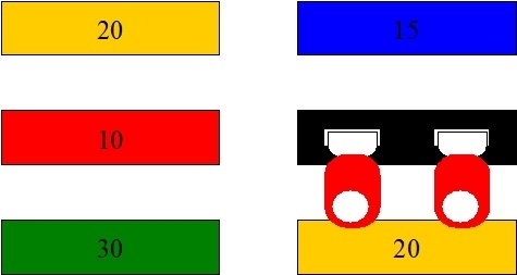
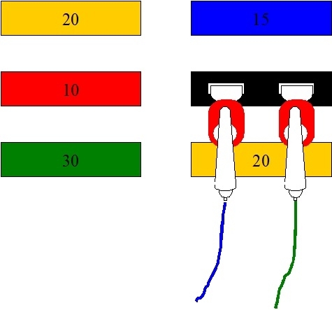
Meters in this price range commonly have three jacks for the probes. Photo 2 shows them in more detail. The black, negative probe goes in the bottom jack. That one is used for all of the functions and ranges. The top jack is used for the red, positive probe for only the highest current range. This meter can measure up to 10 amps DC. ("DC" stands for "direct current" which is used in cars and trucks, and can be stored in a battery). This meter can not measure AC current which is found in house wiring. The middle jack is used for every other function and range except the 10-amp range. The probes are plugged in to the two jacks used most often in the third photo.

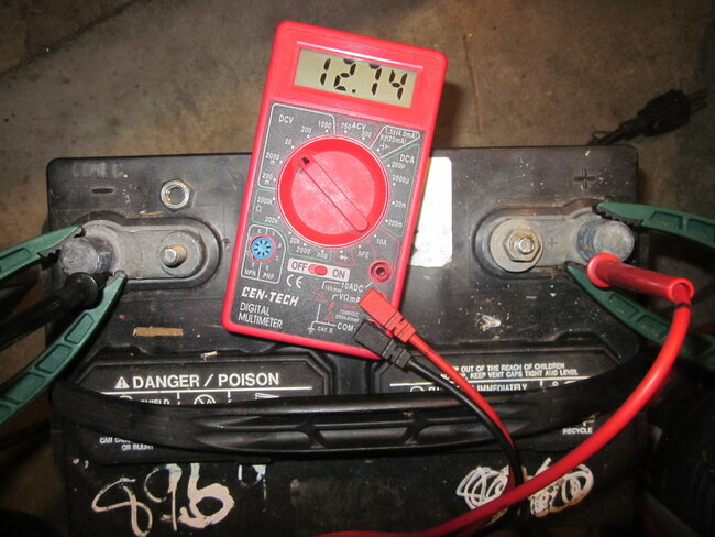
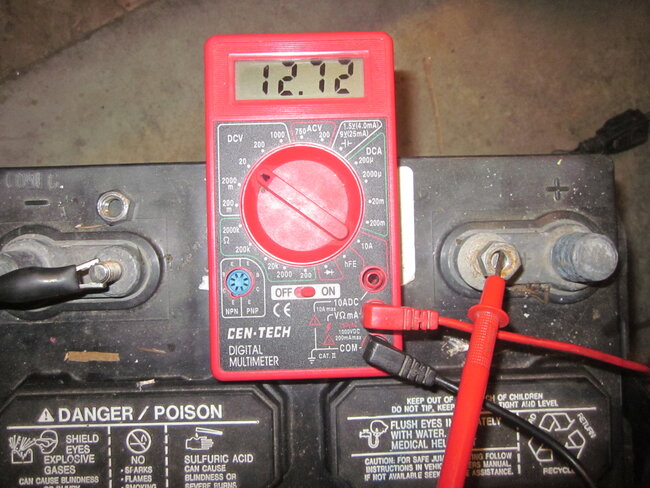
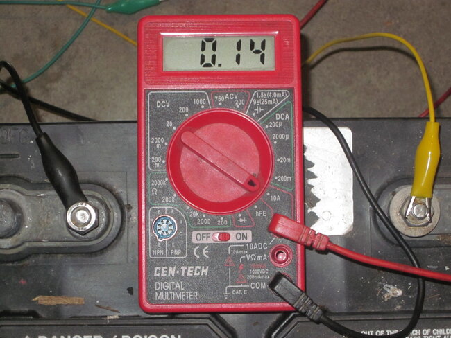
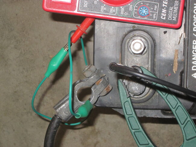
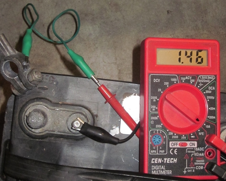
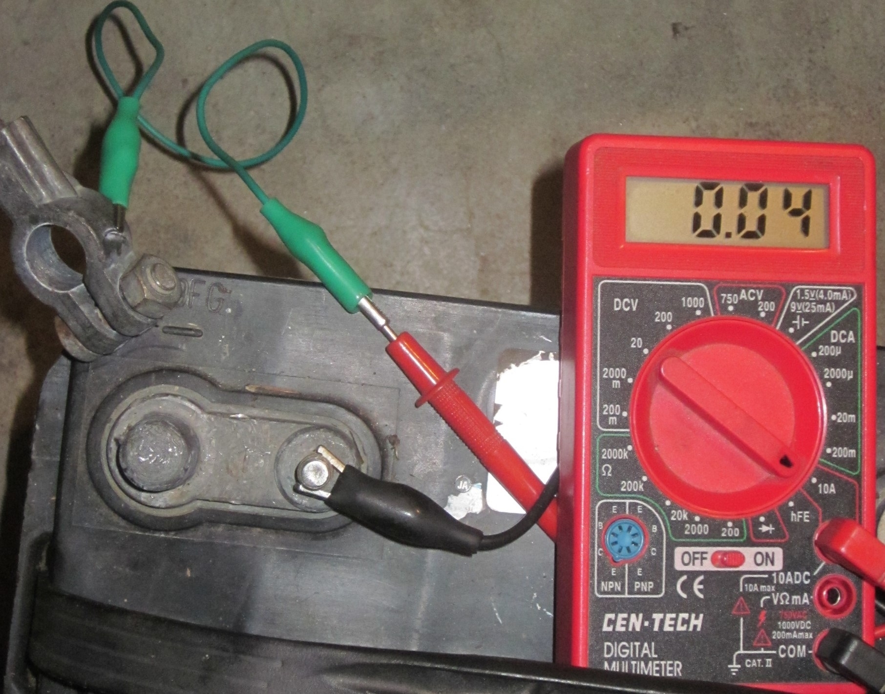
Finally, in the fourth photo, we're measuring this battery's voltage. It takes four hands to hold two probes and run a camera. I only have two, so here I'm using a pair of clamps to hold the probes on the battery's posts. In the fifth photo, it's the same battery and meter, but it's a different negative probe. The probe was broken, and replaced with an "alligator clip". Now only three hands are needed.

The meter is set to the "20 Volt DC" range. That means it can measure any voltage between 0.00 and 20.0 volts. Actually it can only read to 19.99 volts.

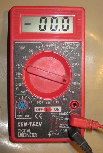
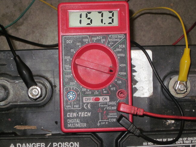
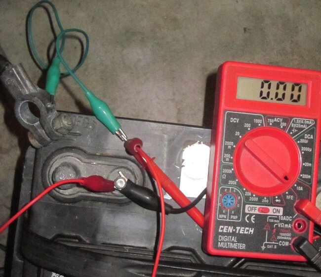
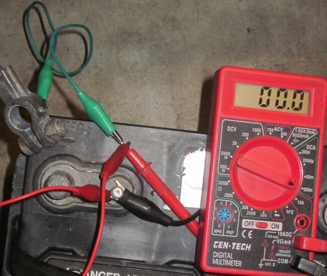
There's two common mistakes that will not damage the meter. The first is switching the probes on the battery's positive and negative posts. The display will include a minus sign indicating a negative voltage. Switch the probes to solve that, however, we're usually just interested in the value, not the polarity, so the minus sign can be ignored. The second mistake is using the wrong scale. In the sixth photo, the meter is set to the "2000 millivolts" range, meaning the 2 volt range. It can only measure up to 1.999 volts, but with an extra decimal place of accuracy. The battery has a much higher voltage than can be measured on this scale, so it's showing a "1". Every digital meter has some means of indicating an "over range" condition. This one uses a "1". Simply rotate the range switch to the next higher range.

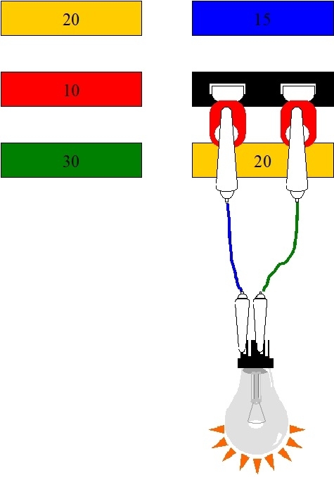
Now to add some confusion to this story, there's two ways to take voltage readings. By far the most common is to take a series of readings AT points in the circuit. Voltage is electrical pressure, and it is always taken in relation to some other point. Most of the time that is "ground", and for cars, that includes the battery's negative post and cable, the frame, body sheet metal, and engine that it's connected to. To say that a different way, the black, negative probe can be touched to the battery's negative post or cable, the engine, or any paint and rust-free point on the body.

Everything electrical can be compared to water in a pipe. A pressure gauge can be installed at any point in the pipe and its reading will be in relation to atmospheric pressure. Atmospheric pressure is common to any point you want to measure water pressure, just like ground is the common point for any place you want to measure the voltage. With water pressure or with electrical pressure, (voltage), we keep taking readings along the circuit until something changes. A loss of water pressure, or a loss or drop in a voltage reading indicates we just passed the defect.

The other way voltage is measured is between two points. The negative probe is not on ground.

Suppose there is a partial blockage in the water pipe. There would be full pressure before that blockage, and reduced pressure after it, but only when water is trying to flow through it. We could measure the pressure before the blockage, in relation to atmospheric pressure, then take a second reading after the blockage, also in relation to atmospheric pressure. Subtract one reading from the other to find the amount of pressure loss across the blockage. There's three places to introduce an error.

A simpler way is to take one reading, but instead of in relation to atmospheric pressure, the gauge would be between the points before and after the blockage. One direct reading would show the amount of pressure drop.

The same thing works in electrical circuits. Excessive resistance could develop, such as corrosion between a pair of mating connector terminals. Normal practice is to measure the voltage before that connector, in relation to ground, then again after the connector, again, in relation to ground. Then we'd have to calculate the difference. The direct way is to place one meter probe on each side of that connector, then take just the one reading. Besides avoiding two sources of error, the meter can usually be set to the 2.00 volt scale for more accuracy. This will be especially helpful in high-current circuits such as for starter motors. The resistance that can develop in a connection can be way too small to measure, but the "voltage drop" across it is the result of that resistance, and that can be measured. This is a story for another time.
Was this
answer
helpful?
Yes
No
Friday, May 19th, 2023 AT 11:45 AM
Tiny
CARADIODOC
  • MECHANIC
  • 33,754 POSTS
Part 2 Measuring Current

Where voltage is electrical pressure, just like water pressure in a pipe, electrical current flow is similar to water flowing through the pipe. To measure current, the circuit has to be broken somewhere, then the amp meter inserted in that break. In this application the meter acts like a piece of wire. It offers no resistance, or restriction, to that current flow.

Photo seven shows the meter switched to the 10 amp range. The probes have been added in the eighth photo. The black probe is in the lowest jack, as always, but the red, positive probe is in the top jack. That jack is only used for the 10-amp range. When you need more accuracy and the current will be less than 200 milliamps, photo nine shows the meter set to the 200ma range.

In the tenth photo, current is flowing through a small LED bulb, then through the meter on the 10-amp scale. The value has been rounded off to 0.14 amps. That's 140 milliamps, so it can be measured on the 200ma scale. In the eleventh photo, the meter is on that 200ma scale. The red probe has been moved to the center jack.

Part 3 Measuring Battery Drain

Side note. One battery cable must be disconnected to test for an excessive current drain. When doing this test, when replacing the battery, or when performing any service that requires disconnecting the battery, always disconnect the negative cable first. We do that because if the wrench should contact anything metal on the vehicle while it's on the cable clamp, nothing will happen. If the positive cable is removed first and the wrench makes contact with a metal part, there will be a dead short that could result in sparks, burns, the wrench becoming red-hot, and a serious explosion if the hydrogen gas given off by batteries is ignited. When reconnecting the battery, always connect the negative cable last.

Measuring for a drain on the battery is very straight-forward for most vehicles built before the mid '90s. For models newer than that, read through Part 4 before connecting the meter. Photo 12 shows the black negative battery cable connected to the battery's post. In photo 13, the cable has been removed, and the meter is connected. A vise-grip pliers works well for holding one probe to the post. A clip lead, (jumper wire) is used for the red probe so it doesn't have to be held onto.

Most meters have an internal fuse for all the ranges except the ten-amp range. To prevent blowing that fuse, start out on the ten-amp range, (Photo 8). If you find less than 0.20 amps, it's okay to switch to the next lower range. Move the red probe to the meter's center jack, and rotate the range switch to the 200ma range, (Photo 9).
Was this
answer
helpful?
Yes
No
Friday, May 19th, 2023 AT 11:54 AM
Tiny
CARADIODOC
  • MECHANIC
  • 33,754 POSTS
Part 4 Measuring Current in Sleep Mode

By the late '90s, a new wrinkle developed when measuring "IOD current". That's "ignition-off-draw" current. Some is normal to keep the memories alive in the multiple computers. Chrysler says with less than 35 milliamps, (0.035 amp), a good, fully-charged battery will be strong enough to crank an engine fast enough to start after sitting for three weeks. Today that is the industry standard unless specified otherwise by the manufacturer. The new clinker is some computers can take up to 20 minutes to go to "sleep mode". Until then, they can draw as much as three amps. We have to wait until they go to sleep mode before measuring the current drain. The additional problem is if anything is done to break the circuit, then reconnect it, those computers wake up again and will need another 20 minutes to go to sleep.

There's three ways to break the circuit. One is to simply disconnect either probe. The next is when the red probe is moved to a different jack on the meter. The third is much less-known. That is simply rotating the range switch. All meters use a "break-before-make switch design. As the dial is rotated, the internal connection to one range is broken, then, as the knob is turned further, it makes the connection to the next range. That tiny gap is all it takes to wake up the computers.

The extra step required to avoid waking up the computers only takes a few seconds; much less time than it takes to explain it. When you want to change the meter's range, use a small jumper wire to bypass it first. Pick the range you want, then remove the jumper wire.

Starting with the 14th photo, the meter and red probe are on the 10-amp range. Current is 1.46 amps. That's too high to measure on the next lower range. After the computers have timed out in the 15th photo, current has dropped to 0.04 amps. That can be measured on a lower range, but that requires removing the red probe to move it to the center jack, and rotating the switch. Both actions will break the circuit and wake up the computers.

The solution is shown in photo 16. The red jumper wire has been added between the two meter probes. Current flow takes the path of least resistance, so it goes through that jumper wire instead of the meter. That's why the meter is showing 0.00 amps. As long as that jumper remains in place, it's okay to move the probe and turn the range switch. In photo 17, those changes have been made, but current is still flowing through the red jumper wire, so the meter still shows 0.00 amps.

Finally, in photo 18, one end of the jumper wire has been disconnected. Current has to flow through the meter now, and it's showing 42.8 milliamps. This range can measure up to 200 milliamps, (0.200 amps), but it has more accuracy than the ten-amp range. If this current would drop even more, as in below 20 milliamps, the next lower range could be used. That would provide another decimal place to the reading for even more accuracy. To do that, reconnect the jumper wire again, rotate the range switch, then disconnect the jumper.
Was this
answer
helpful?
Yes
No
Friday, May 19th, 2023 AT 12:03 PM
Tiny
FONSECA.SARAH1
  • MEMBER
  • 5 POSTS
The fuse does blow. The DIC/RKE fuse on the passenger side fuse block 10Amp blows instantly if I connect the trunk courtesy lamp/occupant sensor connector. The owner's manual says DIC/RKE but then in the actual description HVAC is there as well. Oddly enough though when this specific fuse blows, I have no interior lights and the radio doesn't work. But the Driver Information Center still does, and I think the heat too I can't remember. So, I've just been going along without a trunk light because I like having the light come on when I open my door.

Brand new battery like, less than a month old. Every time I have connected to a scan tool it has the same reading.

Anyways I feel like maybe I just answered my own question. Is it the wires in the trunk probably? Idk why there is no headliner so all those wires near the amplifier are exposed. But I rarely use the trunk, so it didn't even cross my mind until just now.
Was this
answer
helpful?
Yes
No
Tuesday, May 23rd, 2023 AT 6:50 AM
Tiny
FONSECA.SARAH1
  • MEMBER
  • 5 POSTS
Ps. Now the instrument panel light doesn't come on. Just the PRNDL light. So, I definitely have some kind of electrical issue. If I wiggle the dimmer switch (because yes, I've tried turning it up and down? The light will flicker on and off here and there so I guess I just thought it must be something under the dash. Idk

I don't drive often. And the battery doesn't seem to have a drain. It sat over a week and when I plugged the scan tool in it was still at 12.8V. I have a China version tech 2. No codes.
Was this
answer
helpful?
Yes
No
Tuesday, May 23rd, 2023 AT 6:55 AM
Tiny
CARADIODOC
  • MECHANIC
  • 33,754 POSTS
Dandy. This is a horse of a different color. When you have a fuse that continues to blow, my trick is to replace that fuse with a light bulb. When the short is present and the circuit is turned on, the bulb will be full, normal brightness, and hot, so be careful to not lay it against anything that will melt or burn. When you do something to eliminate or isolate the short, the bulb will become dimmer or go out. That bulb will also limit current in that circuit to a safe level to protect the wiring.

The items needed are shown in the third drawing. I drew a common 3157 brake light bulb. That limits current to one amp. With such a small bulb, once the short is gone, the circuit will resume trying to work, but the bulb is going to prevent normal operation. If you want to, you can substitute a head light bulb for this procedure. Those will allow up to five to six amps of current flow. That is plenty to allow lights to light up enough to see them working, or for a motor to run slowly.

The easiest way to connect the bulb is with a pair of clip leads and a pair of generic, universal spade-type terminals. You can find a dozen clip leads for about three dollars at Harbor Freight Tools. These are available in different sizes. Stick with the smallest ones to insure the alligator clip will fit inside the terminal.

To buy the terminals, you'll end up buying a box of typically 50 or more. Instead, any electronic hobbyist will have many of these lying around. The spade end should be no fatter than the terminals on the fuse. It's common for the wire end to be too small in diameter for the alligator clip to fit in. The blue terminal has the insulating barrel removed by twisting it off. Now just stick the terminals in that way, and clip the alligator clips to them. The fourth drawing shows the terminals inserted in the fuse box terminals. In the fifth drawing, a clip lead has been connected to each terminal, and in the sixth drawing the light bulb has been added.

If the test bulb is dim or off, you'll need to do something to make the short occur. That can include opening and closing doors, tapping on the body with a rubber hammer, and wiggling wiring harnesses. When the bulb flashes full brightness, you're in the area of the short. Look for wiring harnesses that fell down onto hot exhaust or engine parts, and for a harness that is draped over the sharp edge of a metal bracket.

If the short is constant with the bulb always at full brightness, a better approach is to unplug various connectors and items until the short goes away. For some reason they don't want to show the fuse box layout to verify we're looking at the same fuse, but I did find it from your description, in the wiring diagrams. The seventh drawing just shows the fuse box location for anyone else researching this problem. The eight diagram is the part with the fuse you're working with. I added a red arrow pointing to it. The blue arrows are pointing to the systems fed by that fuse, and they do include the truck that you mentioned.

To help you get started with isolating different parts of the circuits, I saw the two connectors I have the orange arrows pointing to. If you can find them and unplug them, that will remove those parts of the circuit. If the short is on either of those circuits, unplugging them will make the test bulb get dim or go out. The last two drawings show where those two plugs are located. The notations suggest you're going to have just one of them, depending on the options on the car.

See how far you get now, and let me know what you find.
Was this
answer
helpful?
Yes
No
Tuesday, May 23rd, 2023 AT 8:40 PM

Please login or register to post a reply.

Sponsored links