Hi and thanks for using 2CarPros.
Most often, a hum is related to a bad wheel bearing. When you hear the noise, in a safe area turn left and right. If the sound changes, then suspect a bearing.
Now, which one. If the noise gets louder when you turn right, replace the left front, and opposite. What happens is the weight distribution changes so when you turn right and it gets louder, it's because more weight is applied to the left side.
If you determine one of the front wheel bearings is the problem, here are the directions for replacement.
__________________________
Front
Vehicle Steering and Suspension Wheels and Tires Wheel Bearing Service and Repair Procedures Front
FRONT
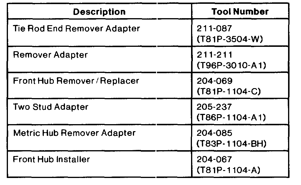
Special Tools
CAUTION: Do not begin this removal procedure unless the following parts are available:
- A new front axle wheel hub retainer (Step 1).
- A new inboard halfshaft joint stub shaft circlip.
Once removed, these parts must not be reused during assembly. Their torque holding ability or retention capability is diminished during removal.
Removal
1. Turn ignition switch to the OFF position and place the steering column in the unlock position.
2. Remove front axle wheel hub retainer.
3. Raise vehicle on hoist.
4. NOTE: Make sure steering column is in the unlocked position, and do not use a hammer to separate tie rod end from the front wheel knuckle. Use extreme care not to damage boot seal.
Remove cotter pin from tie rod end stud and remove slotted nut. Discard cotter pin and nut.
5. Using Tie Rod End Remover 211-001 or equivalent and Tie Rod End Remover Adapter 211-087, remove tie rod end from front wheel knuckle.
6. CAUTION: Use extreme care not to damage boot seal. Do not use power tools to remove the nut, or bearing and seal damage will result. Loosen the nut first, then remove nut from stud using the hex hold feature.
For SHO vehicles, remove vinyl cover from upper link stud.
Remove stabilizer bar link from front shock absorber.
7. Remove disc brake caliper and support with wire to obtain working space. Do not allow disc brake caliper to separate from the front disc brake caliper anchor plate to prevent contamination of the disc brake guide pin journals. Do not allow disc brake caliper to hang from front brake hose. Remove front disc brake rotor. Remove front disc brake rotor from wheel hub by pulling it off the lug bolt. If front disc brake rotor is difficult to remove from front wheel knuckle, strike front disc brake rotor sharply between lug bolt with a rubber or plastic hammer.
If front disc brake rotor will not pull off, apply Rust Penetrant and Inhibitor D7AZ-19A501-AA or equivalent meeting Ford specification ESR-M99C56-A to inboard and outboard rotor/hub mating surfaces. Install 3-Jaw Puller 205-D027 or equivalent and remove front disc brake rotor by pulling on front disc brake rotor outside diameter and pushing on hub center. If excessive force is required for removal, check front disc brake rotor for lateral runout prior to installation.
8. Remove anti-lock brake sensor mounting bolt and front brake anti-lock sensor.
9. Remove and discard lower ball joint nut. Using Remover Adapter 211-211 (T96P-3010-A1), separate lower ball joint from front suspension lower arm.
10. Using Rotunda Spring Compressor 014-00781 or equivalent, compress front coil spring until lower ball joint clears front suspension lower arm.
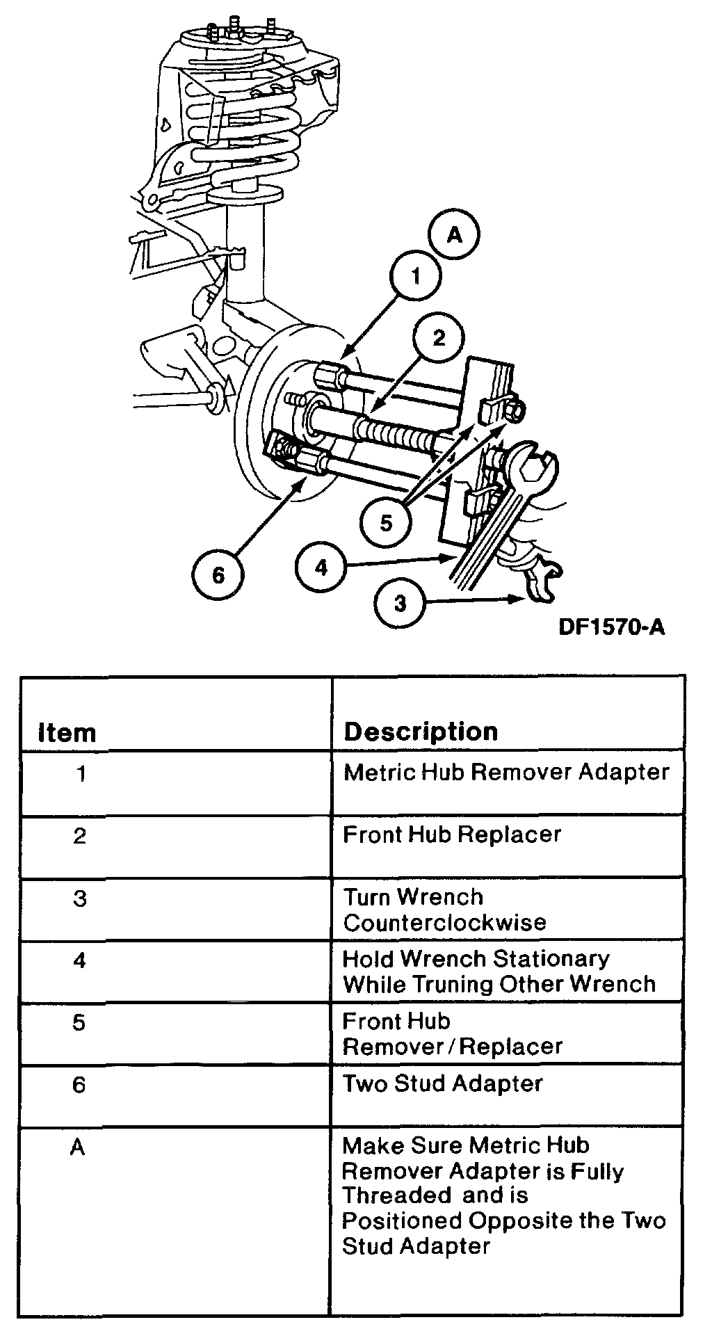
11. Using Front Hub Remover/Replacer 204-069, Two Stud Adapter 205-237, Metric Hub Remover Adapter 204-085 and Front Hub Installer 204-067, press front wheel driveshaft joint from wheel hub. Wire front wheel driveshaft joint to body to maintain a level position.
12. Remove and discard three hub and bearing retainer bolts from front wheel knuckle.
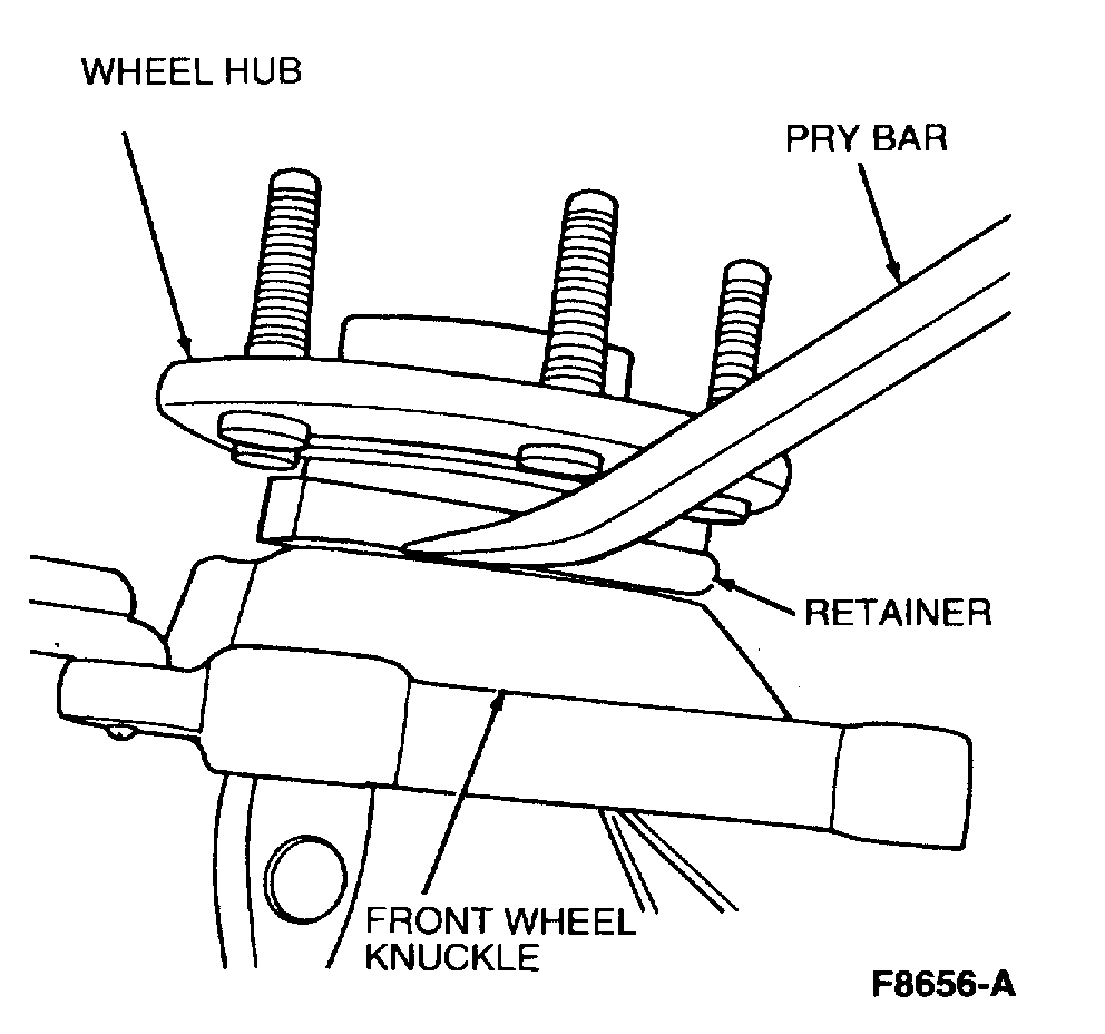
13. NOTE: Wheel hub is not pressed into front wheel knuckle. Do not use slide hammer to remove a stuck wheel hub. Do not strike back of inner bearing race. Use of these methods will damage bearing internal parts.
NOTE: If bearing carrier is corroded to front wheel knuckle, apply Rust Penetrant and Inhibitor D7AZ-19A501-AA or equivalent meeting Ford specification ESR-M99C56-A to the inboard and outboard wheel hub/knuckle mating surface and allow to soak.
Remove wheel hub from front wheel knuckle.
Installation
1. NOTE: If wheel hub is damaged or if any end play is detectable, replace wheel hub. End play is not adjustable. If wheel hub is disassembled, the assembly must be replaced. Remove all foreign material from knuckle bearing bore for correct seating of new wheel hub.
2. Lightly lubricate mating surfaces of bearing corner and front wheel knuckle.
3. CAUTION: Knuckle bore must be clean enough to allow wheel hub to be completely seated by hand. Do not press or draw wheel hub into place.
Position wheel hub in front wheel knuckle. Install three new hub and bearing retaining bolts. Tighten to 83 - 107 Nm (61 - 78 ft. lbs.).
4. Push front wheel driveshaft joint into wheel hub. Hand start front wheel hub retainer.
5. Slowly release Rotunda Spring Compressor 014-00781 or equivalent while guiding lower ball joint into front suspension lower arm.
6. Install new lower ball joint nut. Tighten to 68 - 92 Nm (50 - 67 ft. lbs.).
7. Install tie rod end into front wheel knuckle. Install new slotted nut and tighten to 47 - 63 Nm (35 - 46 ft. lbs.). If necessary advance nut to install a new cotter pin.
8. CAUTION: Use extreme care not to damage boot seal. Do not use power tools to tighten nut or bearing and seal damage will result. Install nut using hex hold feature to prevent the stud from rotating.
Install stabilizer bar link to front shock absorber. Install stabilizer bar link nut. Tighten to 77 - 103 Nm (57 - 75 ft. lbs.). For SHO vehicles, install stud cover.
9. NOTE: Remove rust from the rotor and hub mating surfaces with a medium abrasive pad.
Install front disc brake rotor and disc brake caliper. Tighten caliper anchor bracket bolts to 88 - 118 Nm (65 - 87 ft. lbs.).
10. Install front axle wheel hub retainer. Tighten to 230 - 275 Nm (170 - 203 ft. lbs.).
11. Install wheel and tire. Tighten lug nuts to 115 - 142 Nm (85 - 104 ft. lbs.).
12. Lower vehicle.
13. Pump brake pedal prior to moving vehicle to position brake linings.
_____
Let me know what you find or if you have other questions.
Take care,
Joe
Images (Click to enlarge)
Jan 1, 2019 at 9:24 PM