After replacing the CV axle, the lower control arm and sway bar, the steering pulls to the left?

Tiny
JC-842
  • MEMBER
  • 1998 NISSAN ALTIMA
  • 2.4L
  • 4 CYL
  • 2WD
  • AUTOMATIC
  • 104,000 MILES
Hello All,

I just replaced my CV axle on my car listed above GXE passenger side. I replaced the lower control arm and the axel along with sway bar end link one side only. My problem is the car pulls pretty badly to the left. If you turn loose of the wheel, it's not safe even for a second. It drove much better before the repair. The other issue is the passenger side rim gets pretty warm and the driver's side doesn't. I forgot to mention I replaced the Hub and bearings on that axel as well. I also noticed that my steering wheel is no longer centered, it's off to the right a little. Last thing is when I hit a bump or pothole it sounds like the suspension on that side is bottoming out. Before the repair it didn't do that. Overall, the car drove better before I done anything to it. Im thinking I may have screwed something up but what? I can deal with everything else but pulling left. I might and also when I removed the passenger caliper and rotor, I did not break open any bleeders, so I've not bled the brakes. The pads and rotors look very good. Please any. And all input appreciated. Thanks, JC
Saturday, May 27th, 2023 AT 1:42 PM

22 Replies

Tiny
CARADIODOC
  • MECHANIC
  • 33,738 POSTS
The biggest thing is the car has to be aligned. No two control arms are ever the same, and this is especially true for this design. The placement of the lower ball joint affects "camber" and "caster" for that wheel. Caster has to do with the angle formed by an imaginary line drawn through the upper and lower ball joints, or the lower ball joint and upper strut mount, as viewed from the side of the car. That's similar to how the fork of a bicycle angles rearward at the top.

Camber is the inward or outward tilt of the wheel at the top, as viewed from in front or in back of the car This angle has the biggest effect on pulling to one side. Besides being in specs for best tire wear, it is just as important that it be the same on both sides so the two pulls offset each other. A tire wants to pull in the direction it's leaning.

On rear-wheel-drive cars, caster also affects pulling, but about half as much as camber. With most front-wheel-drive cars, caster has no noticeable effect on pulling.

The hot brake may play into this too, but we should address that later in a separate question. We want to keep each question to one topic to make it easier to categorize them for others to find when researching a similar problem.

I've been finding most alignment specialists do not give their customers a printout when they're done. I always kept a copy for myself, and I put one on the passenger front seat for the car owner, with the things I adjusted highlighted. Ask if you can get a printout of your alignment. If there's still a problem, upload a photo of it for me to look at, or you can just tell me the numbers of interest.

Also mention that you just replaced the lower control arm and the bolt should be checked. Specifically the bolt that goes through the rubber bushing. Most people will tighten that bolt when the car is raised up and the suspension is hanging down. Once the car is lowered onto the tires, that bushing will be clamped in a permanent twist. That greatly shortens its life. Bolts in bushings of that style must only be tightened when the vehicle is sitting at normal ride height. That can be pretty hard to do without a hoist. When the alignment specialist knows about it, he will simply loosen that bolt, bounce the car a few times to settle the suspension, then retighten it. That takes the twist out of it.

Let me know how this turns out after the alignment.
Was this
answer
helpful?
Yes
No
+1
Sunday, May 28th, 2023 AT 4:57 PM
Tiny
JC-842
  • MEMBER
  • 181 POSTS
Thanks Cardio, you're right I did exactly that I tightened everything up in the air that's why I'm getting that hard bottom out at bumps. I did raise. The back up today and loosened the big nut and let the car back down on the tires bounced it up and down. I'll drive it to the front-end guy tomorrow. The car did not pull or ride like a Harley Davidson with no shocks before this repair. I'll keep you posted. Thanks. JC
Was this
answer
helpful?
Yes
No
Sunday, May 28th, 2023 AT 5:42 PM
Tiny
JC-842
  • MEMBER
  • 181 POSTS
Here's the printout from the alignment. Please let me know if you receive it. Thanks. JC
Was this
answer
helpful?
Yes
No
Tuesday, May 30th, 2023 AT 2:18 PM
Tiny
CARADIODOC
  • MECHANIC
  • 33,738 POSTS
The first thing I look at is how the computer is set up. I had all of my values show up with two places after the decimal point for more accuracy. The trade-off is it takes more time to set each adjustment with that much more precision. Your camber readings are only reading to one decimal place, but the right front is so far off, that isn't a concern now.

Over the years I've found most front-wheel-drive vehicles need 0.06 degrees more positive camber on the left wheel to offset "road crown". That's the tilt of the road surface so rain runs off. Most vehicles will drift to the right if that 0.06 degrees isn't adjusted in to compensate for it. When only reading to the tenth of a degree, you can have too little offset or too much, and both could get rounded off to a wrong difference.

In this case, you have minus 2.0 degrees on the right and minus 0.2 degrees on the left. That's a difference of 1.8 degrees which will cause a huge pull to the left. Remember, the tires want to pull in the direction they're leaning. The left wheel is tipped in a little on top, but it's within the allowable range of tolerance. It will cause a slight pull to the right. The right wheel is the problem. At 2.0 degrees, you should be able to stand in front of the car, look back at that wheel, and easily see that it's tipped in on top. That one will cause that really hard pull to the left.

The photo below shows what your front strut assembly looks like. It's hard to see, but my red arrow is pointing to one of the two lower mounting holes that is oval-shaped to allow camber to be adjusted. Chrysler and GM use the lower hole. On GM vehicles, that lower hole has to be ground out to allow an adjustment to be made. Some mechanics won't take the time to do that. Once reassembled, those two bolts are loosened, the wheel is pushed or pulled to position, often many times before we call it "good enough", then the bolts are tightened. On Chryslers, the lower hole is elongated from the factory, and special "cam bolts" with offset heads are used. The adjustment can be set very precisely by rotating, then tightening that bolt.

At a minimum, camber can be adjusted on your car, but if it still has the original struts, that upper hole might have to be ground out. It's already elongated on this aftermarket replacement strut in the photo. Next, those offset cam bolts are available as an aid to the technician, but at extra cost if they didn't come with them from the factory. Either way, I could never justify sending a customer out with the right front wheel like that.

I see that he did fix left rear "toe". That's the direction the wheels are steering. I had my computers set up to read all toe values in inches. Here it's in degrees. One inch of toe-in is the same as two degrees, so starting out with minus 0.34 degrees on the left rear, that equates to 0.16 inches. That wheel is steering away from the center of the car, meaning to the left.

The right wheel is also steering to the left. The positive number means it's turned toward the center of the car. When you add the two rear toe readings, you get the minus 0.19 degrees shown for "total toe". That is the only one that matters as far as tire wear for that angle. Total toe always affects both tires equally on that axle. That's going to show up as a choppy pattern on both tires, more-so on their inner edges. After the adjustment, you have 0.27 degrees toe-in / 0.13 inches. That's very close to 1/8" which is a little higher than I'd like, but it's well within specs for your model. The idea of starting with a little toe-in is road forces are going to tug the wheels back while driving. The goal is for them to have 0.00" toe at that time.

Before the alignment both rear wheels were steering to the left which causes "dog-tracking". They gave that an unusual name, "steer ahead". What that means is the computer looks at the two rear toe readings, then as the final step in the alignment, it tells us to set the steering wheel perfectly straight, then it shows us where to set the two front toe values to make them perfectly parallel to the rear wheels. That ensures we'll end up with a straight steering wheel, regardless of what we have for the rear wheels steering to either side. That's also why we always perform 4-wheel alignments, even on vehicles with solid rear axles. That compensates for any dog-tracking.

There's nothing to discuss about the two front toe "before" readings because we know those changed a lot with the new parts. They had to be better before. You have three things to look at in regard to the alignment. The first two are the straight steering wheel, and pulling to one side. You see those all the time, and you know right away when either of them changes. The third one is tire wear patterns. Those take some time to show up, so what you see now is how they were wearing before you replaced the parts. About half of the time after an alignment, bad wear patterns will clean up in a few thousand miles. Often the wear is so bad, even when the alignment is corrected, that wear causes the blocks of tread to keep on wearing the same way. To say that a different way, don't panic if you have bad wear patterns now and it doesn't clear up.

The right front tire is going to wear very quickly on the inner edge. To put this in perspective, a wheel that's perfectly straight up and down has 0.00 degrees camber. If you imagine a wheel laying on its side, that would be 90.0 degrees. A common camber spec is close to 0.50 degrees, give or take a little. That moves the vehicles weight to right over the larger inner wheel bearing on older cars, and it affects a number of things related to handling. Some older GM rear-wheel-drive cars from the '70s and '80s called for as much as 3/4 degree camber. That was quite a bit, but it provided best tire wear. Ford has always had design problems with their steering and suspension systems. By far the worst was with their early Escorts. They came from the factory with 2 7/16 degree camber on the front and seriously negative camber on the rear. We could straighten up the rear wheels with aftermarket repair kits, but there was no physical way possible to fix that horrible front camber. Tires on every one of them wore out in 15,000 miles. The dealer would tell you it's because they weren't rotated. Fact is on the front they wore the outer edges, and on the back they wore the inner edges, so you were still lucky to get 15,000 miles on a set of tires. They did that because it made them ride much smoother than their competitors' little cars, so they sold a pile of them. A lot of people got killed in those cars too because of the design of their tie rod ends.

My reason for including this story is that 2 7/16 degrees on the front was extremely easy to see by anyone driving in the next lane. They looked like a new-born horse with its legs going in four different directions. Of course you never learned about the miserable tire wear until after you made the first few payments. By then it was too late. The minus 2.0 degrees you have on the right front is almost that bad. I would question why that wasn't corrected. The possible answers I can think of include a rusted bolt that can't be loosened, camber is already adjusted out as far as it can go, or they offer some type of bargain alignment where they only adjust toe. Camber can be tedious and frustrating to get it right, but to see that right front wheel and ignore can't be justified.

The last possibility has to do with chassis ride height. Every manufacturer has published specifications and drawings to show where the measurements must be taken. On older vehicles with upper and lower control arms, they form part of very rigid geometric angles, and those angles go through very specific changes as the car bounces up and down as it goes down the road. All of that careful design goes out the window when ride height isn't correct. That includes raised trucks and lowered cars. Sagged front coil springs can change the angles so much that camber may not have enough range to allow it to be set to specs.

Another often overlooked cause is one weak or broken coil spring that lets one corner of the car droop. If, for example, your left front spring is very weak, it will just let that wheel move straight up into the wheel opening, but it will cause the hood, body, and right suspension all tilt to the left on top, and that can be more than enough to see that minus 2.0 degrees on the right front wheel. You can start by measuring from the ground to a matching point on each corner of the car to see if they're the same. If the left side is lower, say an inch or more, it might be time for new springs. Beyond that, to know if the measurements are correct, you can visit any alignment shop and ask them to show you. They all have small books that show every year and model, exactly where to take the measurements, and what they should be. I can find that for you too at a later time, after I put a new battery in my wireless mouse.

I have a similar alignment computer made by Hunter, and I have the option to make the same style of printout. This one is best for explaining to car owners what the angles are. Just as important to me, besides the actual values shown, are the ranges of the specs. Those are shown in tiny numbers on each upper corner of the red and green bars. (Green means that value is in specs). There's a different printable page with a lot more secondary angles listed, and the range of tolerances is shown more predominantly. If you get the option, get a copy of that more detailed printout. The numbers are harder to understand, but that's why you have me. I have some drawings I put together to explain some of those things.
Was this
answer
helpful?
Yes
No
+1
Tuesday, May 30th, 2023 AT 7:15 PM
Tiny
JC-842
  • MEMBER
  • 181 POSTS
Thanks for that bit of information. To be honest those numbers are for you pros The information concerning the hole drilling and modifying that strut is very interesting. I think this guy gave me the ole El Cheapo Alignment that's why he didn't put the added effort to fix this issue. I paid $129.00 for 1 year warranty. It was $200.00 for the lifetime warranty. I'm not capable of modifying the strut so my question is. Will replacing the strut/ Struts do any good? A pair runs $160.00 but am I wasting my money? I'm heading upwards of 500.00 at this point. By the way. The steering wheel is now facing 12:00. If you want me to post this as another question let me know. Thanks Cardio. I need your advice on what to do next. If new strut won't fix this leaning wheel
Should I break out the drill myself? Thank you. JC
Was this
answer
helpful?
Yes
No
Wednesday, May 31st, 2023 AT 2:39 AM
Tiny
CARADIODOC
  • MECHANIC
  • 33,738 POSTS
This job is actually less expensive than you might think, and it's very common.

First of all, find out if that one-year warranty, which is already better than you normally get, covers only mistakes made by the tech, or if it will include a realignment after doing the strut work. If you come in with new struts, or even other parts, they could say the resulting need for another alignment isn't their fault, so you have to pay again. Usually the concern is this type of adjustment method can slip when you hit big pot holes. That's the type of thing they typically want to take care of for you.

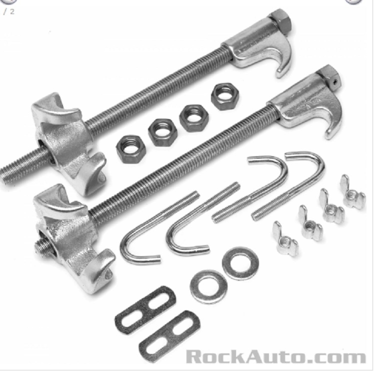
As for the struts, there's three ways to approach this. One way is to replace both front struts. That includes a significant safety concern with flying coil springs. I've seen two shoot out of the compressor. One took out an 8-foot overhead light fixture. The one that happened to me shot all the way across the shop, out the door, and through the parking lot. It made so much noise, the office manager who was sitting behind two closed doors ran out to see what had happened. Now we all use wall-mounted compressors, but do-it-yourselfers don't have access to those unless you have a friend who is a mechanic. The safety issue is with the portable compressors, especially those referred to as "clamshell" compressors.

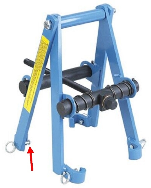
I can walk you through the job. You can most likely borrow a strut compressor from an auto parts store that rents or borrows tools. In my city, they make you buy the tool, then you get a full refund when you take it back. If you choose to keep a tool, you still take it back, then they give or order you a brand new one.

Once you remove the assembly, the spring only needs to be compressed less than an inch to remove the force on the upper mount. That upper mount has a rubber insert in it that can deteriorate, but you can't see that until after it is taken apart. If you need to order new ones, the car has to sit until they arrive, or you have to put it all back together, then start all over days later. I've had to do that more than once with customer cars. Same is true if there is a rubber "isolator" between the bottom of the spring and the metal plate it sits on. Chrysler used those to reduce the transmission of road noise, but here again, you can't really tell if they're worn until everything is taken apart. The new struts can be installed without those parts, but it lowers the front end by about 1/2". My parts department never stocked them because they showed no sales history for them. I pointed out there was no sales history because for years the previous tech was leaving out the worn ones rather than leaving that car torn apart on his hoist for days. Once they began keeping a pair in stock, I was using them on about one in ten strut jobs. Made for lots of customer satisfaction at very low cost. Be aware most car brands don't use those isolators, so this isn't an issue.

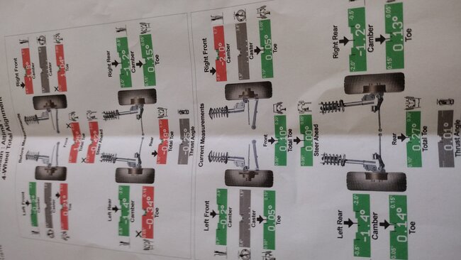
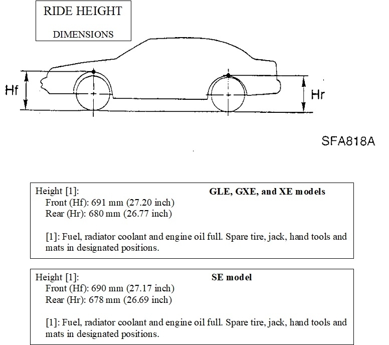
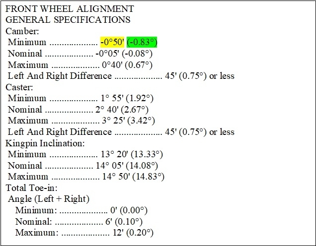
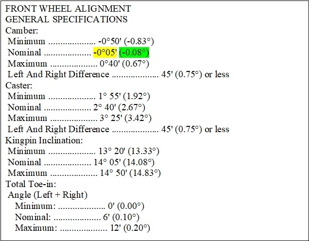
Before you go that route, measure the front ride height. The drawing shows to take them at the top of the wheel openings. This method does not account for non-standard tire sizes, so you have to make allowances for that. If you find one side is lower than the other, or if both sides are significantly lower than specs, the better value is to install a pair of "quick struts". Those are the struts, coil springs, upper mounts, dust boots, and those isolators if they are used, all in one package already assembled and ready to install. This restores ride height to specs, and you don't have to worry about the condition of the upper mounts or the safety concern of a spring popping out of the compressor. When you pay me to do this job, you save much more in labor time than the small higher cost over just the bare struts. I compare installing new bare struts with old, used springs and mounts to buying new shoes, but using old, ragged shoelaces to hold them to your feet.

Even with either new bare struts or quick strut assemblies, you can't be sure one of the mounting holes will come elongated. As I mentioned, those on Chrysler and Chrysler replacement struts are always oval-shaped, and original GM ones are always not. The holes in aftermarket replacement GM struts usually are, but if not, you have to grind them out. That job only needs to be done once to make them adjustable.

I think you're in for unnecessary misery if you try to drill the holes out. I could be wrong, as I never tried it that way, but the easier way is with a die grinder and metal-cutting bit. You can find them in electric models, but all I've ever used are air-powered. You can find them at Harbor Freight Tools, Walmart, or any hardware store. Be sure to wear safety glasses, and I recommend wearing disposable rubber gloves. I never wore the gloves, and always ended up with a few tiny metal slivers in my hands.

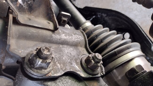
On Chryslers and GMs, the lower of the two holes gets elongated. I've had some import models where the adjustment can't be made that way due to the spindle bumping into the bottom of the strut body. I suspect that's why they show grinding the upper hole for your car. The way to see what's taking place is to raise the front end off the ground, support it with jack stands under the frame, not the lower control arms, remove the wheel and tire, then remove the upper bolt, and finally, loosen the lower bolt. If things are rusted tight, you may need to loosen that lower nut a good full turn, then hit it with a hammer to push the head back a little to release the clamping force. Since the suspension is hanging freely, there won't be a lot of pressure on that lower bolt.

Now grab the bottom of the strut and pull it out toward you. Doing so makes the strut tilt in on top more than before, but it makes the spindle tip out on top, which is what we're after. As an educated guess, I'd say you want the top of the brake rotor to move outward roughly 1/4" Don't waste your time trying to measure that. It's just an estimate to get you in the ballpark. Once you pull it out that much, snug the lower bolt. If it wants to pop back in or out on its own, lightly snug the bolt first, leaving it just loose enough that you can pry it out a little, then tighten the bolt more to keep it there.

At this point you're going to find the upper holes are no longer lined up with the hole through the spindle and you can't get the bolt in. This is where you have to grind the holes on both sides of the strut until the bolt will go in. With a new, sharp cutting bit, that can be done in as little as a couple of minutes, or it can take longer, depending on how far you have to cut. You only need to cut the holes as much as is needed to get the adjustment you need. That's impossible to know by eye, so a good recommendation is to grind the holes 3/16" larger. That should be more than enough to get 2.0 degrees more camber.

As an alternative, if you look on the Rock Auto site, under "Suspension" for your model, they show two different styles of special bolts at the top of the list of parts. I'm not familiar with using either one, so hopefully they come with instructions. I still prefer grinding the holes.

Oh. Yeah; don't get excited if the cutting tool suddenly starts flying around in the hole. Hold it tightly and vary the speed to help prevent that. It's one of the few miserable parts of the procedure.

You can use a little grease on the bolt threads if you want to, but don't put anything on the spindle where it mates with the strut, especially no anti-seize compound. A coworker thought he was doing me a favor when he replaced some struts, but that left them with absolutely no clamping force. The adjustments kept slipping every time I set the car back down on the hoist. Eventually I got so frustrated, I tightened and tightened the first bolt so much that I pulled it apart with a hand ratchet. That bolt was over 5/8" in diameter, and I snapped it with hand tools. That's when I had to take everything apart and found that anti-seize compound. Better to just leave everything dry.

The last thing, once everything is reassembled using the same struts, is to observe that up to now, the two front toe readings are good, and the steering wheel is straight. That won't be the case once the wheel is fixed. This next comment isn't too important, but if you look at how far the lower ball joint is off the ground, then look at how far the stud for the outer tie rod is off the ground, most likely you'll see they aren't the same. If they are, this last comment has less value, but on most cars, the tie rod end is a good two to six inches higher. The reason this observation has value is when you tip the wheel out, the lower ball joint stays in place, but the steering arm on the spindle moves out, along with the top of the spindle / bottom of the strut. The attaching point of the tie rod end moved out, but the tie rod didn't. If the steering linkage is in back of the half shaft, as most are, this causes that wheel to turn to the right when you tip it out. How much it turns can be pretty significant, enough in fact to cause tire squealing as you drive back to the alignment shop. Because we know you're starting with a straight steering wheel, here's an easy trick to get that right front toe back close to where it should be.

Because this procedure made the right front wheel turn to the right, you have to turn the steering wheel to the left to kind of get the car to go straight. Before you put everything back together to prove that to yourself, adjust the tie rod's linkage longer. The jamb nut is normal thread. The nut is typically an 18 to 21mm, and if you can get straight on it, you may be able to loosen it with one hand on the wrench. Once it's loose, rotate the inner tie rod end to back it out of the outer one. There's usually a six-sided area made to fit an open-end wrench, but we just use a large pair of pliers. As you rotate that, you'll see the brake rotor turning to the left. A good guess is to lengthen that link by about 1/8" as a starting point. That should be enough to make the car drivable.

Now for the fun part. Once everything is reassembled, go out and drive the car and see where the steering wheel is. If it's still to the left, that linkage needs to be extended a little more. I would often take a wrench with me on test drives, then park on the side of the road to make this adjustment to get it close while waiting my turn on the alignment rack. When you get it to where the steering wheel is nearly straight, you'll know toe is back where it was right after the alignment.

To add unnecessary confusion, another way to look at this, is when the steering wheel is off-center to the left, the wheels are supposed to be too to match that, but right now, they aren't. You have to adjust toe to put the wheels where they match the steering wheel, and that means turning something to the left. Since we know the left wheel was correct and it hasn't been touched, it can only be the right wheel that needs to be adjusted. This only works when one strut is replaced or modified. If you replace both struts, this still works if you do one at a time. Adjust toe on that wheel to get the straight steering wheel back, then go to work on the second side and do it the same way. This still only gets you close. An alignment is still needed. Toe can go in or out of specs with as little as 1/8 turn on the inner tie rod end, but you'll never see that change in the steering wheel. It will show up later in the tire wear patterns.

Don't leave the jamb nut loose, but you don't have to over-tighten it either. With being loose, the inner and outer tie rod ends will hammer against each other and wear away the threads. They'll get loosened and retightened during the realignment, so your goal here is to just get everything close.

The only thing that can lead to disappointment is if you find out you didn't grind the holes big enough to get the full 2.0 degrees needed. By recommending 3/16", I think that should be enough, but there's no harm in going a little bigger to be on the safe side.

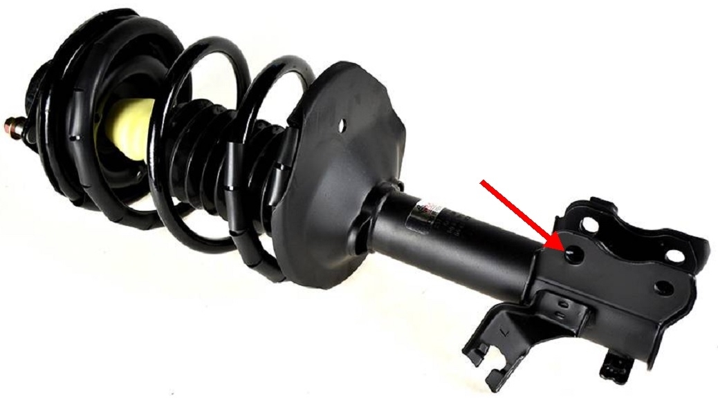
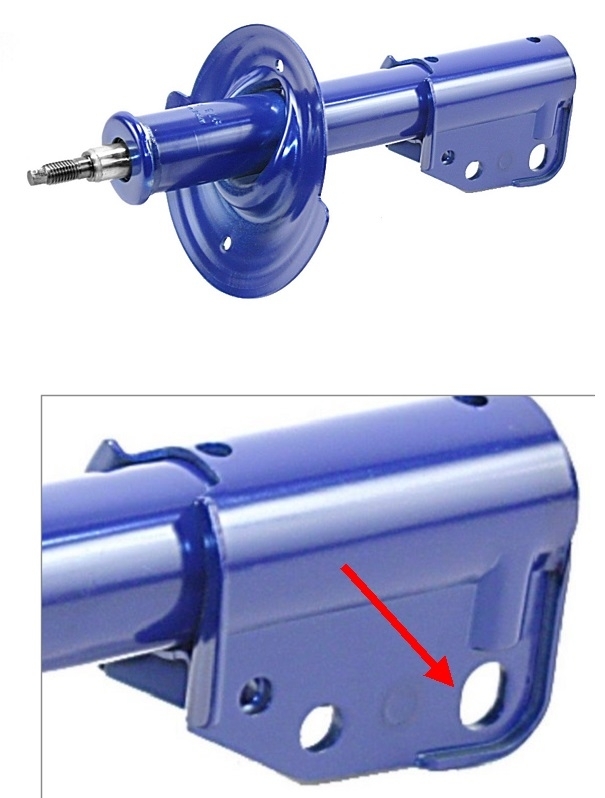
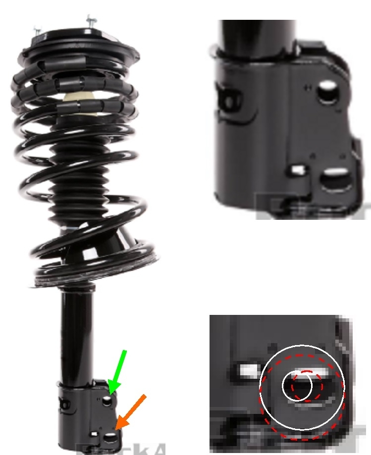
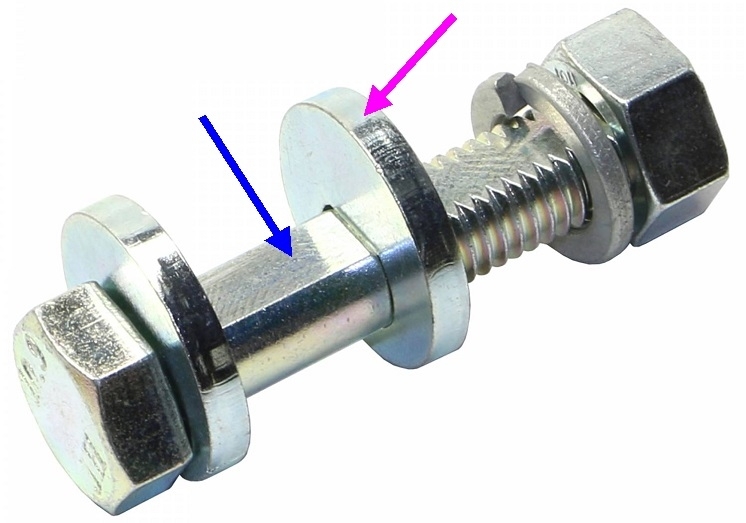
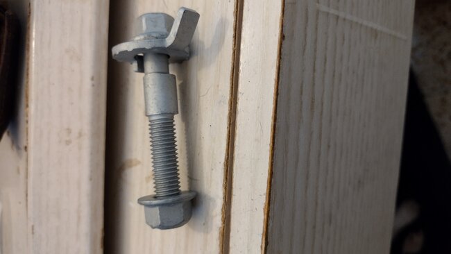
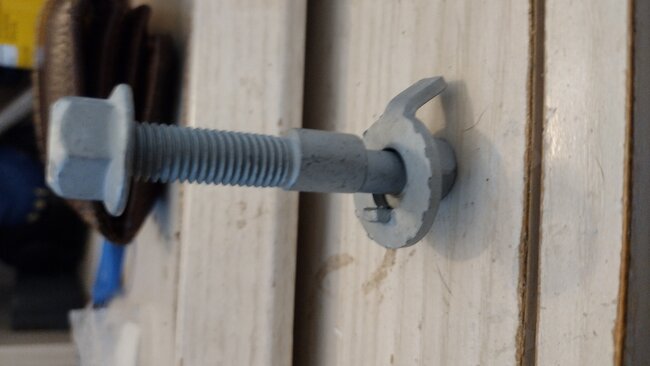
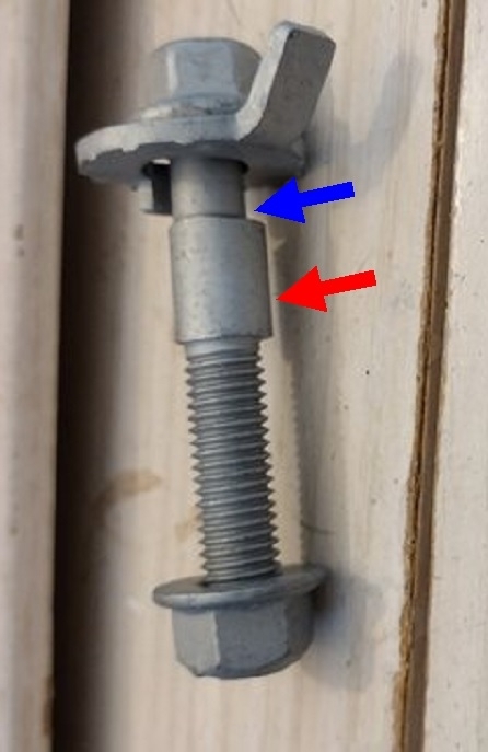
The second photo shows a front strut from a Caravan The third photo shows an aftermarket replacement for a Chevy Cavalier. On both of these, the lower holes is elongated, and if you look right above it, you'll see a raised area that looks like a bump. Also, notice the lip on the bottom corner. Both are easier to see in the Chevy photo. That lip and bump form a pocket for an eccentric bolt to fit in. That's the bolt I mentioned with the offset head. As the bolt is rotated, that head is forced to sit in that pocket, so the shaft of the bolt moves back and forth. That pushes or pulls on the hole in the spindle to force it to move. Better yet, since it can't rotate or move once it is tightened, it really holds it in place well when driving over bumpy roads. Most Chrysler models come with those cam bolts. They have to be added on GM alignments, at extra cost, but only the first time they're needed. A lot of shops don't stock those bolts, so they just rely on the original ones to hold everything in place. That can be acceptable for your car too.

The only thing I didn't discuss yet is removing the large nut at the top of the strut's shaft.
Don't do that before the spring is compressed. Each spring holds up over 1,000 pounds of car, so there's that much pressure on it as it is removed from the car. To remove the nut that way would send the upper mount airborne. It most likely would not take out an airplane, but it will do serious damage to heads. This step is avoided when installing quick struts.

On most struts, as shown on these two, but hard to see, there's a hex on top to hold the shaft from spinning while the nut is backed off with another wrench. That's fine when doing this once, but it takes way too much time for a professional. The way I get them off is to use a 1/2" air impact wrench, but I pulse the trigger repeatedly. To hold it steady will just spin the shaft endlessly and make it dizzy. By pulsing it, the shock backs the nut off a little each time I run them on the same way, but with new struts it's a good idea to do that rather slowly. The shaft spins a little each time, and spinning too much too fast can overheat and melt the rubber o-ring seal at the top of the strut body. Those are lock nuts, so they won't just spin on by hand. You'll need the impact wrench or two hand wrenches.

Once that nut is tight, the last step is to loosen the spring compressor. As you do that, observe the bottom end of the spring must be rotated to meet the raised section of the metal mounting plate. That's called "indexing" it. Any time you're reinstalling used struts, wipe off any dirt on that plate. That, and small pebbles that get caught in there can cause a crunching noise. Also note the top end of the spring indexes with a mating formed area under the upper mounting plate. That upper plate is in two parts with a bearing in between. That's to allow the strut to rotate with the steering system while holding up all that weight. It's not uncommon to find the three bolts on top don't line up with the three holes in the inner fender. Normal procedure is to lift the assembly up and insert the three bolts first, loosely install the nuts to keep it there, then rotate the strut by hand to line up the bottom with the spindle. You may have to grunt with both hands, but some struts turn rather easily.

Many models also have brake hose brackets ad anti-lock wheel speed sensor wires attached to the struts. Don't forget to reinstall them.
Was this
answer
helpful?
Yes
No
+1
Wednesday, May 31st, 2023 AT 8:52 PM
Tiny
JC-842
  • MEMBER
  • 181 POSTS
Wow. That's a lot of information. I'll measure the front distance as shown in the photo I don't believe those struts are bad I measured both sides at each corner of the front end and came up with pretty much the same on both sides. I measured from the pavement to the top of the wheel well. And no particular difference in height. I also took a straight edge actually two-foot level and flat against the tire from top to bottom there's a one-inch difference in the two sides. The passenger side needs to come out at the top of the wheel one inch to match the driver's side. I think I'd prefer to try the special camber bolts if I can find them. And after hearing your story about the Strut exploding, I'll buy the fully assembled struts. To be on the safe side. If I can find the camber bolt's I may try using them with the original strut on the passenger side. Before buying a dye grinder and trying to elongate the strut hole. But I also want to let you know the warranty on my alignment is for as many times as needed for one year. They assured me that there was no problem. The reason the Tech. Didn't go out of his way to fix the issue with the strut was because I bought what's considered the economy. Alignment. The lifetime warranty was double the price and I didn't know then what I know now. I didn't realize how involved the alignment could be. I'm going to remove the wheels again and take a good look at my struts so far, I've seen no oil leaking there's no excessive movement in the struts there's no bounce in the front end. And I think if I'd needed new struts the car would not have handled as well as it did before the axel and control arm replacement. I'm very sorry for taking so much of your time, you've been great and explaining everything in precise detail. If I can avoid modifying the original strut, I may not be capable of that job I'm in my 70s and it's hard for me to getting up and down under this car. Not to mention the stress. I wish I could hop in the car and come to you and let you deal with this headache. Thanks Cardio, you are Great. JC
Was this
answer
helpful?
Yes
No
Wednesday, May 31st, 2023 AT 10:03 PM
Tiny
CARADIODOC
  • MECHANIC
  • 33,738 POSTS
In case I wasn't clear, the strut doesn't have to be removed to grind out the hole. Only the top bolt has to be removed temporarily, and the bottom one loosened.

If you go with the special bolt, let me know which style you get and how it works. There's a good chance you'll find one at a local auto parts store. I have a suspicion you'll have to remove both bolts to get the top one installed. With just the top one removed, I don't think the spindle will tip out far enough. Maybe it can be installed right through the holes in the strut. As I said, I never used that style.

I didn't mean to scare about replacing struts. When it comes to that time, I have a number of suggestions. The first photo below shows the "clamshell" type of compressor. This is the type used when the two incidents occurred with springs popping out. If you look at my red arrow, this is the first one I've seen with the special locking pins to hold the arms to the spring. I didn't have those. They eliminate the safety concern.

The style you're more likely to borrow from an auto parts store is shown in the second photo. Here again, they have added a safety feature in the four J-bolts to hold the hooks to the spring. One big advantage to this style is they can be installed on the spring while the strut is still bolted to the car. If you use a floor jack to raise up the lower control arm an inch or two, you'll start to compress the spring / collapse the strut. Then you can tighten the nuts by hand. When the jack is lowered, the spring will already be compressed enough to remove all pressure on the upper nut.

With either of these designs, I recommend tightening the nuts by hand with a wrench. To save time, most professionals use an air impact wrench, but too often that seems to result in grinding away the threads on the tool's long bolt.

The next suggestion is to remove the strut assemblies yourself, then take them, along with the new struts and / or springs, to a shop, and let them transfer the parts. If they know you're coming at a certain time, this will take them just a few minutes. Also consider asking at an auto parts store, especially the place you bought the parts from. They may offer that service or have a shop they recommend.

For my last comment of value, consider looking for a local community college with an Automotive program. We had over a dozen people who would sit on a broken car for months if necessary to bring us their projects because they knew the value those real-world jobs had for our kids. We charged ten dollars per hour for what the job was supposed to take, not what we actually spent on it which included discussions and demonstrations. We also got parts at real good discounts, then marked them up 10 percent to form a "breakage" fund in case we damaged something. Our students were very responsible and well-supervised.

The low cost is the huge draw for a lot pf people, but the trade-off is it could take days or weeks to get your car back, depending on the type of work it was in for. Also, we taught eight areas, each for eight weeks, and each only once per year. You have to wait until what you need fits what is being taught, otherwise we're in competition with the local shops that hire our graduates. You can have the entire job done, from removing the struts to the alignment, or they may be willing to just elongate the one hole. They have to consider whether they're backed up with job requests, and how much learning potential the job presents. If they've already had a dozen strut and alignment jobs, enough for every student to replace two or three, they may be looking for a variety of other learning experiences, and decline to take in more strut work. On the other hand, it's just as likely they haven't had enough strut work and will gladly take on your needs. The only way to know is to stop in and ask.
Was this
answer
helpful?
Yes
No
+1
Thursday, June 1st, 2023 AT 12:05 PM
Tiny
JC-842
  • MEMBER
  • 181 POSTS
I. Got your message and I will definitely keep you posted whichever way I decide to go. I bought the bolt's on eBay. 13.00 for 4 bolts. One bolt pull's 1.75 +/- With the option of using both if needed. The passenger side needs to come out one inch or close to it. If the bolt doesn't do the job I'll go with grinder. And when you say oval is that oval as in up and down or sideways? Maybe that's a crazy question but if you could give me an illustration of how the hole should look before and after that way I'll have peace of mind knowing I'm doing the thing right. I'd hate to make the hole where the bolt doesn't fit because the hole was not done the right way. I'm still trying to figure out how to get a picture off of eBay to send you. They don't provide any instructions on installing the bolt's. The bolt is threaded halfway then it has a hump or shoulder then it has a washer like thing with a tab on it. I'm not sure how it's going to work or if it will work But maybe the alignment shop will be able to demonstrate. It's going to be next week before the bolt's come. If your curious go to eBay and type in 1998 Nissan Altima GXE camber bolt's and you can see what I tried to describe. By the way they come in 12 mm and also 14 mm. Mine are the 12mm.. Thanks CARADIODOC. JC
Was this
answer
helpful?
Yes
No
Thursday, June 1st, 2023 AT 1:27 PM
Tiny
CARADIODOC
  • MECHANIC
  • 33,738 POSTS
I've never tried to describe this through typing. It works better face-to-face during a demonstration, but we'll see how it goes.

The front strut in this first photo is for my old '88 Grand Caravan, but the same part was used for over ten years on all their minivans and most of the front-wheel-drive cars. It's the best photo I could find. The bottom is enlarged in the upper right photo to show the elongated lower hole. Right now both holes in your struts look like the upper hole in these photos. To make yours adjustable, all that is necessary, at a minimum, is to grind the hole oval-shaped like this lower one, but on your car it would be the upper one. You actually might get the same results by grinding the lower hole too, but you'd have to experiment with that. There may be some reason they want that done on top.

You can see the lip to the right of the lower hole. Also notice the raised area to the left of the lower hole. Those form the pocket for the cam bolt to sit in.

I hope I can make this understandable. The second photo shows a replacement cam bolt for this strut. The pink arrow is pointing to one of the two offset eccentric washers. On the original bolts, the one next to the head is machined as part of the bolt. It can't be removed, but it works the same way. The blue arrow is pointing to a flat area on the bolt. The holes in the washers have matching holes to key them to the bolt. That forces them to rotate along with the bolt as you turn it with a wrench or ratchet and socket.

Now for the fun part. In the bottom right, I expanded it even more, and added the red and white circles to show to location of the washer. As the bolt is turned, the washer has room to allow it to move up and down in that pocket. But as they rotate, the lip and raised area force the center hole to move left and right. The white circles show the washer is centered left to right in the pocket, and the shaft of the bolt is to the left as far as possible. Remember, the hole in the spindle is still round, so where the shaft of the bolt goes, so does the spindle.

The red circles show the bolt has been rotated a quarter turn. Left to right the washer is still centered in the pocket, but being off-center, it has moved down. More importantly, the hole has moved outward, (to the right in this photo). The bolt's shaft has moved there and taken the spindle with it. The washers have forced the bolt's shaft to move along with the hole in the spindle. When you don't have this cam bolt, as in when we grind the holes elongated on GM vehicles, the movement of the spindle in relation to the strut is accomplished by you pulling or pushing on the strut. Once you get it to where you want it, you tighten both bolts. More confusion on that in a moment.

There's two big advantages of this cam bolt design. The first is once you get camber to where you want it. The washers being trapped in the pockets holds the adjustment there while you gather up the tools to tighten the bolts. When you're reusing original regular bolts on GM vehicles, or on yours, there's nothing to hold it in adjustment while you tighten them, and I guarantee they're going to move from the weight of the car. I promise, more on that in a moment.

Where this is less important for you is no matter how far you get camber increased, it can only become better than what you have now, and you can get that with the wheel off and you tugging on the strut while you tighten the bolts.

Your goal is to increase camber by 2.0 degrees, or even a little more. My goal during the alignment is to get camber as close as possible to the middle of the range of specs, AND to get left camber to end up 0.06 degrees higher than the right side to offset road crown.
You're shooting for degrees. I'm shooting for hundredths of a degree.

Now for the part I mentioned, but you won't be tested on this later, or even have to remember it. When the car is aligned, it has to be sitting perfectly level on the drive-on hoist, with things like tire pressures and sizes all correct. If the driver is especially heavy, we might add some weight to the driver's seat, but the specs we're going for take into account the vehicle is empty, including the trunk. Because I did this for ten years at a very nice family-owned Chrysler dealership, and I was their only alignment specialist, I got real good at making the camber adjustments. We also had a lot of trade-ins of other brands, and I worked for an independent shop previously, so I was familiar with adjusting camber with no cam bolts. Either way, the first step is to reach over the tire and feel around for the two large nuts. They can be on the front or the back of the strut. Step one is to fit the socket on a nut, with a long extension, then a really long 1/2" ratchet. Both nuts get loosened only about 1/2 turn. Now you move the socket to the other side and find the lower bolt head. Use the ratchet to rotate the bolt. As you do that, you'll see the wheel move in and out on top. There's a little play in those washers. If you rotate the bolt to pull the wheel in on top, then tighten them that way, that little play could come back and bite you if the driver hits a big pot hole. The spindle could slip a little until the washer bottoms out in the pocket. That can be significant enough to change camber over half a degree which is more than enough to introduce a pull, and to turn that wheel toward the center of the car, resulting in an offset steering wheel too. To prevent that, I always adjusted camber too low for a starting point, then rotated the bolt and washers to pull camber higher, then I tightened the nuts. That way the washers were helping to hold the adjustment from slipping The only way the adjustment could slip is if the car went airborne and gravity was pulling the wheel out on top, but there just isn't enough weight on the suspension system for that to occur. That extra holding power is the second advantage of those cam bolts.

The bolts you ordered for your car work the same way by pushing the spindle's hole in or out, but in this case the pocket is the upper hole in the strut that's still round. The effect and the holding power are the same, but you can't watch what's happening because you can see the bolt's shaft. You can see the results as the wheel tips in and out. This same design was used on older Toyotas, and according to a friend at the local Toyota shop, they usually get rusted tight and have to be pounded apart, cleaned up, then reassembled with a little grease.

If you choose not to install cam bolts or special bolts, you end up with the same thing as with GM vehicles. In that case, I find it easier to raise the car off the hoist, loosen the two nuts the same as before, put my foot at the bottom of the tire, pull the top of the tire out by hand, snug the nuts, set the car back down on the hoist after going through the calibration of the alignment projectors, then I'm starting the real alignment with too much camber. Now I reach in back and loosen just the lower nut and leave the upper one not quite tight, but tight enough to hold that spindle from slipping. Now I nudge, poke, tap, cry, or swear at the tire until the car's weight causes the spindle to slip just a little at a time until I slowly sneak up on the perfect setting. If I get it, that's when I reach behind with the socket and tighten the nus.

The next frustration is when you're changing camber, you're actually raising or lowering that wheel a little, but we see that as the corner of the car goes up or down a little. That's why gravity helps us lower camber. If we need to raise it just a little, we loosen the nuts again just to the point they're almost about to slip, then I put my foot on the bottom of the tire, and pull out on the top like a monkey. If I'm lucky, the adjustment will hold long enough to get the nuts tight. This is where we can raise the car again to pull camber higher, or tug or push on the wheel a dozen times before we call it "good enough". The other clinker is when you increase camber on the left, for example, that raises the left corner of the car, and since the right suspension is attached to the car, that wheel also tips out a little. The two sides do interact a little, which adds to how much we have to run back to the other side and redo that adjustment.

There comes a point where we have to give up and be satisfied with what we have, especially when we're working on a model that's known to be very forgiving on that precision. I found a lot of GM vehicles will still go straight with camber readings that would suggest otherwise.

To add a part to this story that I'll never admit out loud, when we have a finished alignment that we know is more than acceptable, and a the final test-drive proves there's no pull and the steering wheel is centered, but we know the customer is overly-picky, we can make the numbers on the alignment computer change to what he will be happy with by letting a little air out of a tire, opening a door just a few inches, or even just leaning gently against the car. That can change the camber readings by as much as one or two tenths of a degree, but to put this in perspective, those numbers go way out the window when you pour the owner into the car. We know we have a good alignment, and fudging the computer screen just when we hit the "Print" button, keeps the customer happy. Of course you have to do those things when the customer isn't watching, but in my case, when they snuck back to see how it was coming, my managers never chased them out of the shop because I kept them happier by explaining what I was doing for them. Once they saw how touchy the readings were to little things like butterflies landing on the fender, they were more likely to leave happy.

Now you know way more than the average competent do-it-yourselfer. If you run into trouble with the new bolt, try to post a photo of it, or give the the eBay listing number so I can see it. Together we should be able to figure it out.
Was this
answer
helpful?
Yes
No
+1
Thursday, June 1st, 2023 AT 8:47 PM
Tiny
JC-842
  • MEMBER
  • 181 POSTS
You are fantastic, not that I understand all you've explained. To say the least it's a lot to absorb all at once. But what I admire is that you care about what you do enough to try and explain in such detail the ins and outs of what seems to me to be a very tedious job for detailed and precise numbers. I really appreciate that you're willing to take time to try and help me with such a job. I will send you the info concerning the bolts so you can see what they look like. They appear to be completely different than the one you showed in the illustration photo the add says if one bolt does not do the job you can use two for more accuracy I guess. It says to put the bolt's Head in from opposite directions if you have to use them both. Thanks again. I'll try and send the link. JC
Was this
answer
helpful?
Yes
No
Friday, June 2nd, 2023 AT 5:22 AM
Tiny
JC-842
  • MEMBER
  • 181 POSTS
Cardio I'm sending you an update I went to the parts store and bought a set of bolts instead of waiting a week. Sending you the pic of what they look like.
Was this
answer
helpful?
Yes
No
Friday, June 2nd, 2023 AT 11:04 AM
Tiny
JC-842
  • MEMBER
  • 181 POSTS
Cardio I'm sending you an update I went to the parts store and bought a set of bolts instead of waiting a week. Sending you the pic of what they look like.
Was this
answer
helpful?
Yes
No
Friday, June 2nd, 2023 AT 11:05 AM
Tiny
JC-842
  • MEMBER
  • 181 POSTS
Hey, I think these Cam bolts are to small but parts say this is the right ones but I'm not too sure about that. JC
Was this
answer
helpful?
Yes
No
Friday, June 2nd, 2023 AT 11:15 AM
Tiny
JC-842
  • MEMBER
  • 181 POSTS
Old bolt's.
Was this
answer
helpful?
Yes
No
Friday, June 2nd, 2023 AT 11:31 AM
Tiny
JC-842
  • MEMBER
  • 181 POSTS
Cardio I'm having the worst luck. You just about have to go with part in hand. They say it's 14MM
Was this
answer
helpful?
Yes
No
Friday, June 2nd, 2023 AT 11:34 AM
Tiny
CARADIODOC
  • MECHANIC
  • 33,738 POSTS
Okay, the threaded part of the bolt needs to be considerably smaller in diameter than the original bolt, otherwise it won't be able to move the spindle. It looks like the widest part of the cam, (red arrow) should be the same size as the original bolt.

One side of the strut is going to ride at the blue arrow. The other side will ride somewhere on the threaded area of the bolt. Thinking of that pocket formed on each side of the Chrysler strut, and the eccentric washers that sit in them, your original round holes in the strut become those pockets. If you want to get technical, where the eccentric washers on the Chrysler bolt pushes the strut in or out, on yours, the eccentric is inside the spindle and pushes it in and out. The result is the same, it tips the wheel in or out on top. They're saying if one bolt doesn't give you enough range, you can use a second one in the other hole.

To elaborate on my description of those eccentric washers, as you rotate the bolt, those washers can move up or down within the pockets, but as you continue to rotate the bolt, they push in or out on the strut to cause the change. Similarly, as you rotate your bolt, at two quarter turns, the inner eccentric will also drop down or move up and cause no change, but the next quarter turns, it will push the spindle in or out. Pop one of those bolts in and you'll see what happens as you rotate it.

If nothing moves as you rotate the bolt, you may need the larger of the two sizes listed. Don't forget that to allow this change to occur, the top bolt has to be loosened a little to eliminate its clamping force.
Was this
answer
helpful?
Yes
No
Friday, June 2nd, 2023 AT 12:05 PM
Tiny
JC-842
  • MEMBER
  • 181 POSTS
Okay, so the bolt goes into the bottom hole and not top hole? And I'm still not getting what that piece. Over the bolt is. It looks like something I've seen on tractor attachments that you turn to take up the slack in the attachment. In the photo it's in between the hump of the bolt. And the head Is that where it stays? I noticed it has little barb's on one side. Is that some sort of stop to lock the bolt when it's tightened down? You would think alignment shops would have these bolts at their disposal. Thanks for making me aware of bolt situation. I was going to return them tomorrow. So I guess I'll tackle this again in the morning. Enjoy your weekend and hopefully I can update you on Monday. And by the way I bought the little magnetic level/ degree reading tool. Looked like it could be useful in telling you how much adjustment to apply. Take care. JC
Was this
answer
helpful?
Yes
No
Friday, June 2nd, 2023 AT 3:55 PM
Tiny
CARADIODOC
  • MECHANIC
  • 33,738 POSTS
Those Magnetic angle finders are a quick trick we don't really share because they are not precise enough for anything, but in this case all we're interested in is gaining 2.0 degrees. That can tell you you've moved camber the right way, and when you've moved it close to the correct amount. The secret is to attach it to the brake rotor, which is parallel to the wheel, and to install at least two lug nuts to hold the rotor solidly in position.

I've used that tool too when replacing struts when it's going to be necessary to drive the vehicle to the alignment shop. As long as nothing else changes between removing one strut and installing the new one, I set the angle finder to 0 degrees, switch the struts, adjust camber until it shows 0 degrees again, then tighten the bolts and move on to the second strut. You'll still end up with an off-center steering wheel, but camber on each wheel will be close enough to make the car drivable.

I don't have an answer about the tab on the washer. I looked at that multiple times, but never figured it out. Without playing with one of those myself, I don't know what it is supposed to do. I did forget to mention earlier that this type of adjuster is simply an aid in setting camber very precisely where you want it, but it's the tightening of the nut and its clamping force that is what is relied on to prevent it from shifting or slipping later while driving. Let me know if the torque spec for that nut is listed on the packaging or in any directions it came with. Normally I'd suggest "common sense" for the torque spec, but I do that from experience, with a long-handled ratchet. With those huge cam bolts on Chryslers, I'm too puny to over-tighten them or strip the threads. That may be possible with bolts of a smaller diameter. The good news is the final tightening is going to be done by the alignment specialist, so it's up to him to know how tight is tight. I'm pretty sure this won't be the first time he's seen this.
Was this
answer
helpful?
Yes
No
+1
Friday, June 2nd, 2023 AT 8:00 PM
Tiny
JC-842
  • MEMBER
  • 181 POSTS
Do you think one bolt will be enough? Also, the bolt's spec is 1.75 degrees what is that in relation to the 2.0 which is the goal here (right)? And is this considered plus adjustment? Or minus? The top of the wheel has to come out to a 2.0 reading. I want to make sure I get this right. And I will take a photo and send you it does come with basic instructions. So, here's what I understand of how this thing works the cam bolt has two tabs one on each side the tab on the back side of the washer goes inside the bolt hole when tightened the outside tab is supposed to face the hump on the bolt and when tight has to face towards the hump. And the barb's on the backside of the washer grabs the metal when the bolt is completely tightened. And also, it's supposed to face or be aligned with the arrow on the head of the bolt. Which you probably can't see due to the bolt sitting on the head in the pics I sent you. What do you think about it? Will one bolt be enough to get to the reading I need? Be looking for more photos tomorrow, the third I'm not sure if I'll hear from you because of the weekend. But that's fine you have been a huge hep. JC
Was this
answer
helpful?
Yes
No
Friday, June 2nd, 2023 AT 10:47 PM

Please login or register to post a reply.

Sponsored links