Hi and thanks for using 2carpros.com. If you see a leak from the valve cover, they should be replaced. Here are general directions for replacement:
https://www.2carpros.com/articles/replace-valve-cover-gasket
Here is a general video which shows one being replaced:
https://youtu.be/RjnW9C7RFdc
These are the directions specific to your vehicle from alldata.
REMOVAL
Remove crankcase ventilation tube from valve cover and remove from engine.
Remove retaining nuts for engine control sensor wiring and remove engine control sensor wiring from valve cover retainer stud bolts and position out of way.
Remove ignition wires from spark plugs and valve cover.
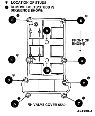
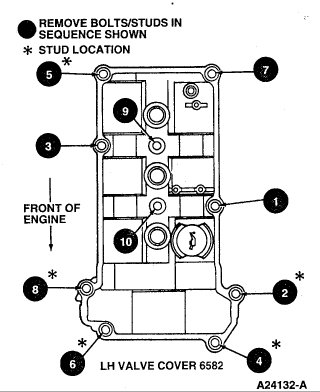
Loosen valve cover retaining bolts and stud bolts following the removal sequence shown.
Carefully remove valve cover from cylinder head. Remove integral valve cover gasket from valve cover.
INSTALLATION
CAUTION: Cleaning Aluminum Surfaces
Do not use abrasive grinding discs to remove gasket material; use only plastic manual scrapers. Do not scratch or gouge aluminum sealing surfaces.
Clean valve cover sealing surfaces using a shop towel and Metal Surface Cleaner F4AZ-19A536-RA or equivalent meeting Ford specification WSE-M5B392-A.
NOTE: Tighten all fasteners within six minutes of applying sealer or sealer will begin to cure and may not seal properly.
Install new valve cover gasket onto valve cover.
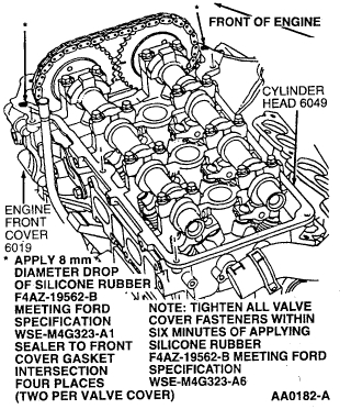
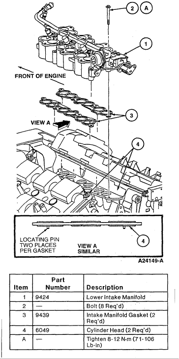
Apply 8 mm (0.31 inch) diameter bead of Black Silicone Rubber F4AZ-19562-B or equivalent sealant meeting Ford specification WSF-M4G323-A1 at two places on the valve cover sealing surfaces where the engine front cover and cylinder head contact.
Tighten valve cover bolts and stud bolts in sequence shown to 8-12 Nm (71-106 inch lbs.) within six minutes of applying sealer.
Follow removal procedure in reverse order to complete assembly.
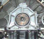
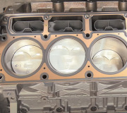
I've attached pictures of the tightening sequence for you as well as what you will find once removed.
Once you have things apart, make sure to check the intake gasket for leaks as well. If you find a leak, here are the directions from alldata to remove and replace the components. I've also attached pictures for guidance.
WARNING:
FUEL UNDER PRESSURE
Fuel in the fuel system remains under HIGH PRESSURE for long periods of time, even when the engine is not RUNNING. To avoid injury or fire, release the fuel pressure from the fuel system before disconnecting any fuel line.
FIRE HAZARD
Do not smoke or carry lighted tobacco or an open flame of any type when working on or near any fuel related components. Highly flammable mixtures are always present and may be ignited, resulting in possible personal injury
REMOVAL
Relieve fuel system pressure. Refer to Powertrain Management.
Disconnect battery ground cable.
Remove upper intake manifold.
Disconnect fuel supply and return lines from fuel injection supply manifold. Refer to Powertrain Management.
Disconnect engine control sensor wiring from fuel injectors and wiring retainers. Position engine control sensor wiring out of the way.
Disconnect vacuum supply line from fuel pressure regulator.
CAUTION: Do not loosen or bend intake manifold runner control actuator cable retainer bracket. Bracket alignment is critical and potential damage to the intake manifold runner control actuator (IMRC) may occur.
NOTE: Use care when removing actuator cable from the IMRC Lever.
Disconnect the intake manifold runner actuator control cable from the lower intake manifold (IMRC) lever and bracket.
Disconnect the ignition wires from the LH cylinder head (cylinder numbers 4, 5 and 6). Position ignition wires out of the way.
If required, remove fuel injection supply manifold and fuel injectors from lower intake manifold (IMRC).
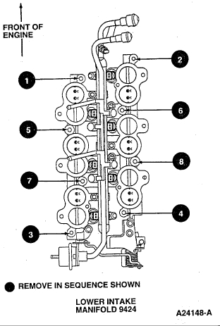
Remove lower intake manifold to cylinder head retaining bolts in sequence shown.
CAUTION: Do not loosen or damage intake manifold runner control actuator cable retainer bracket.
Remove lower intake manifold (IMRC) from cylinder heads.
Remove intake manifold gaskets from cylinder heads and discard intake manifold gaskets.
Images (Click to make bigger)
Monday, May 7th, 2018 AT 7:45 PM