Fuses are not blown so what is next to check?

Tiny
CADEPHILLIPS
  • MEMBER
  • 19 POSTS
Hopefully it will not take too long to get that wire and connector replaced. It had not even dawned on me that that was corrosion, I thought that it was the short, and that is why it was burned and broken in two. I will also try to get the rest of the back of that fuse block cleaned up and remove the spider nests. Who knows that might reveal something else. I'm also going to need to brush up on where these relays/switches are that I will need to check. But I guess before I do any of that I will get that wire fixed and replace the two 30 fuses with the correct 15 amps. Then I'll be able to start on checking all those spots you labeled with the colored arrows. With time change coming up tonight I should be able to have more daylight to work on it anyway and maybe take some better pictures that may help.
Was this
answer
helpful?
Yes
No
Saturday, March 13th, 2021 AT 3:30 PM
Tiny
CARADIODOC
  • MECHANIC
  • 33,738 POSTS
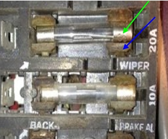
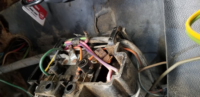
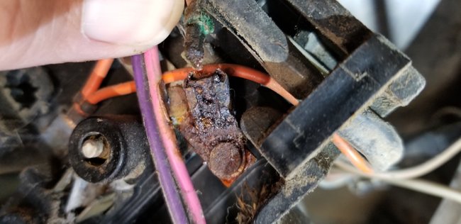
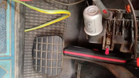
I wouldn't do any repairs yet, or even replace the fuses yet. There's a dozen good places to find the defect, and one of them could even be where the 12-volt-feed fuse box terminal has the fuse snapped into it. Continuing on with my previous procedure, you would touch the meter's or test light's probe to the fuse box terminal, then to the end of the fuse plugged into it. Those two points are shown with the arrows in the first photo. If you find 12 volts on the fuse box terminal, (blue arrow), but 5.4 volts on the fuse, (green arrow), that connection has to be where the high resistance is. Look at the rust on the terminal just above the green arrow. That is a dandy place to suspect a high-resistance connection.

If you were to pop the correct fuse in first without doing any testing, the scratching action is going to scrape off enough of any light film of corrosion that the high resistance is gone. The circuit will work now and you'll never know why it didn't work before, and you'll always be worried it's going to act up again.

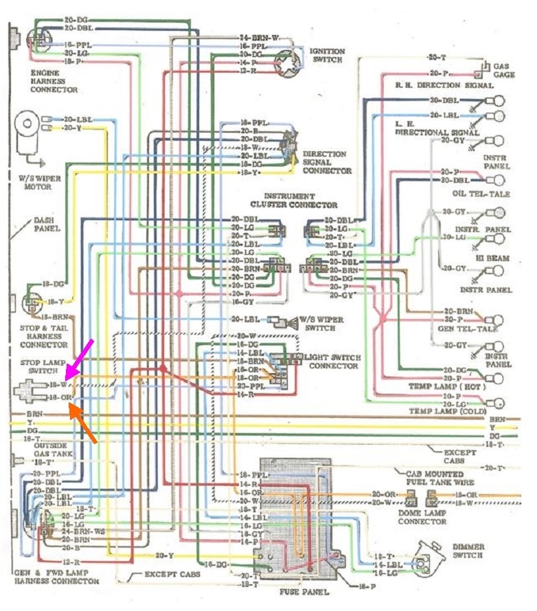
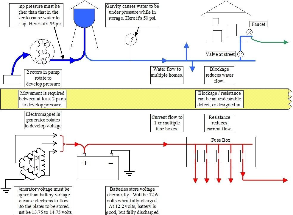
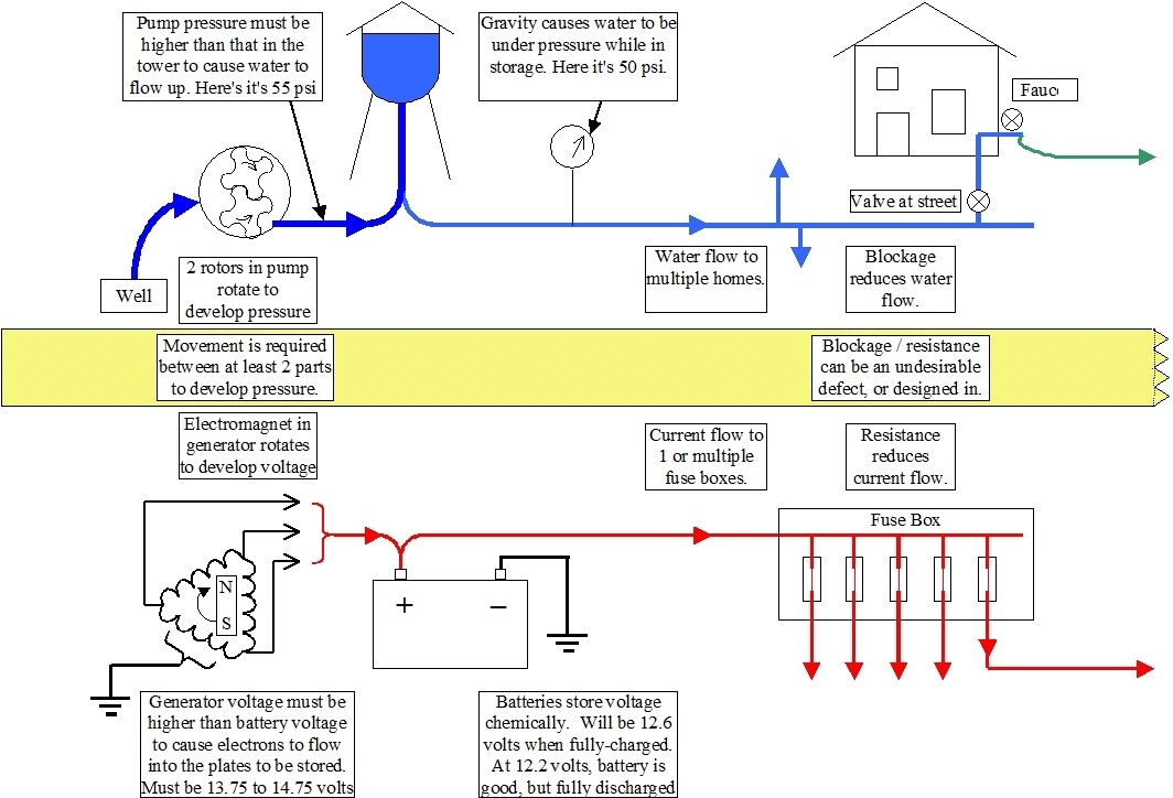
Electrical specialists including myself often complain about Chrysler's wiring diagrams that bounce around between multiple pages in the service manual, and each page has just a tiny portion of the circuit on it. Even back in the '90s, there could be over 100 pages of diagrams to cover just one or two car models. But here is the exact opposite. The entire electrical system for a '72 Dodge Challenger fits neatly onto two pages and is easy to follow. GM's engineers thought it would be easier to put everything on one page, and here's what they ended up with in the second diagram. It is completely impossible to know where each circuit runs because they don't show which switch wires are connected when turned on, or which terminals in the fuse box have a fuse between them. This is just too impossible to follow, however, coupled with my wondrous memory, we can still figure out where to go.

My memory of wire colors in the '70s still holds true for a '66 model. The brake light switch is shown at the far left of this diagram, and the orange wire is the 12-volt feed. If you follow that wire to the right and down, you'll see it comes from the fuse box, but I also noticed it runs to the head light switch first. That tells me that circuit feeds something more than just the brake lights. That has to be the tail lights and / or the head lights. If we knew which other lights that feeds, and if those lights work correctly, we would know everything, including everything inside the fuse box has to be okay. On the other hand, if the brake lights are dead, and the circuit at the head light switch is also dead, we would know the defect has to be before the head light switch.

As a side note, if that orange wire at the head light switch is feeding the head lights along with the brake lights, a 15-amp fuse is not big enough for that circuit. One high-beam head light draws close to six amps. Two would draw a total of 12 amps. There needs to be some safety margin built in to prevent nuisance blown fuses. They normally don't want to exceed 80 percent of a fuse's rating under normal circuit operation. Add in any tail lights that might be on that same fuse, plus the intermittent brake or signal lights, and even a 20-amp might be too small. Once we get this solved, we can worry about figuring out which are the correct fuse sizes.

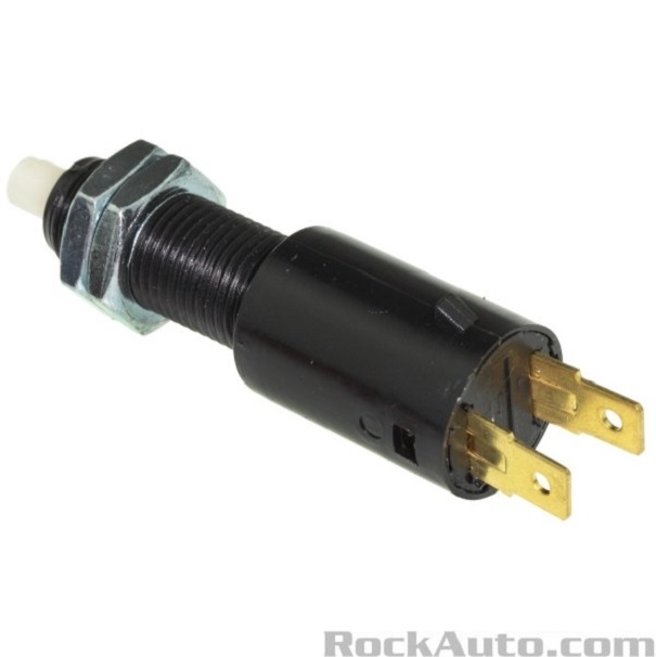
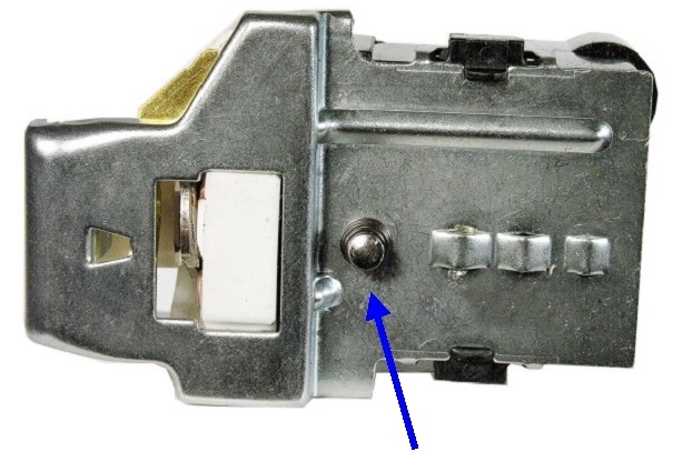
The first step is to measure the voltages in the fuse box, but I'm going to jump ahead since you asked about the switches. The third photo shows what your brake light switch looks like. The arm of the brake pedal presses on the white button at the top left to turn the switch off when that pedal is released. Either terminal can have the orange wire plugged into it, then the white wire will plug into the other terminal. The switch mounts to a metal bracket that may be attached to the steering column or to the frame of the dash board. The terminals will be open and exposed on the back where the wires go in. Those are easy places to take voltage readings.

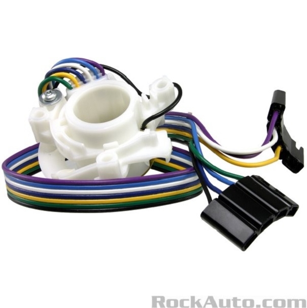
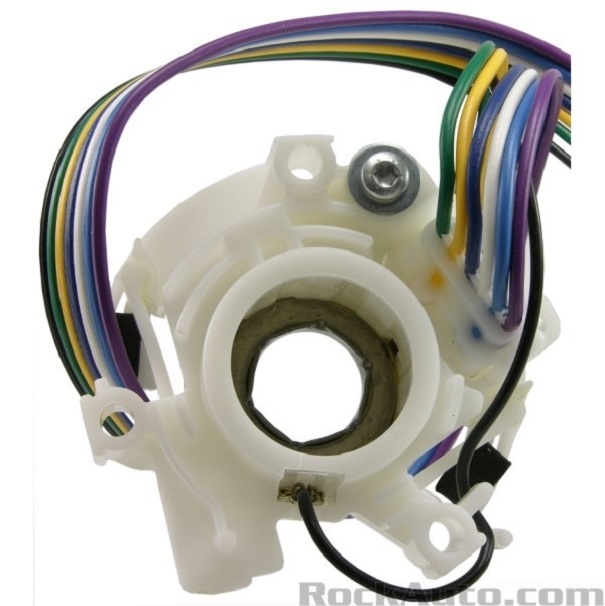
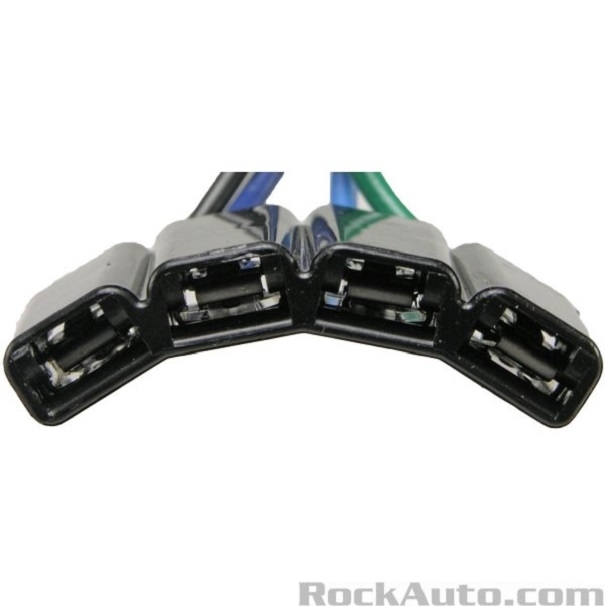
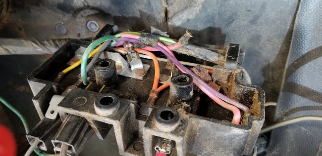
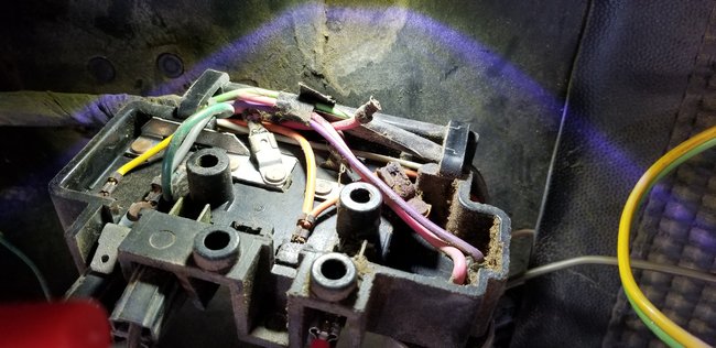
The white wire runs to the signal switch. It sits right under the steering wheel, but testing it gets to be real easy. The fourth and fifth photos show two views of this switch. The switch contacts are on two halves that are riveted together and are non-repairable. One half is stationary and mounts to the steering column. The other half rotates, or slides over the stationary half to make different connections for the turn signals. As such, the turn signal lever is bolted to that movable half. You can see in the fifth photo the wires run into the assembly, and there's no place to take voltage readings. You have it much easier. The fourth photo shows the two connectors, and you'll see that long wire harness they're attached to. Those run through the steering column and come out under the dash board.

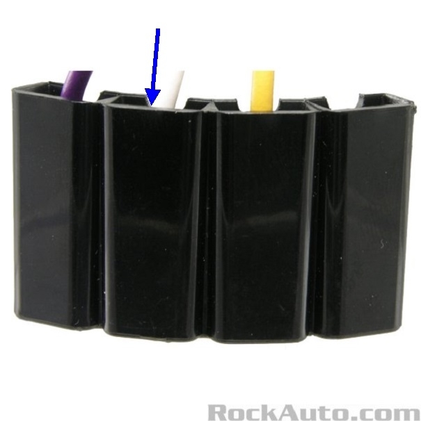
The sixth photo shows one of those connectors, and the seventh one shows one connector turned just enough that we can see where the wires run in to the terminals. That's where you can poke the probe to take the voltage readings.

When you apply the brakes, the brake light switch switches on the 12 volts that goes to the signal switch. With the signal switch released, current flows through it and out on two different circuits, one for the left brake light and one for the right brake light. If the defect is before the signal switch, both brake lights will be dead.

What many people forget or overlook is the brake light switch only supplies the 12volts for the brake light function. You still need 12 volts to the signal switch for the turn signals when the brake light switch is off. That means there has to be a second 12-volt source to the signal switch. That one comes through the flasher and it is likely to be on its own fuse. We know that because the brake light circuit can operate any time, but the ignition switch has to be turned on for the signals to work. The point of this part of the story is the two rear circuits might work properly when the signal switch is turned on, but not when the brake light switch is turned on. There is value in knowing that. If the signals work in the rear, that is proof those bulbs, and the wiring all the way back to the signal switch, including at least part of the signal switch and some of the connector terminals have to be okay, and there's no need to do any testing in those areas.
Was this
answer
helpful?
Yes
No
+1
Saturday, March 13th, 2021 AT 5:09 PM
Tiny
CADEPHILLIPS
  • MEMBER
  • 19 POSTS
That last part of your response is spot on and I will explain that hopefully in a bit. But 1st I think I may have not communicated well about the 5.4 V, So it may take a couple replies from me to get my point across I hope. The only time there was 5.4 volts was only in the bottom 2 fuses and only when I applied or pushed on the brake pedal. It was on both sides of the fuses and on both the terminal and the actual fuse. All the other fuses acted normally even if they didn't work. So I tested each spot on the bottom two fuses and terminals before I ever removed the fuse block. Each spot made the test light light up and read 12.7 on my Volt meter. Then as I pushed on the brake pedal it instantly went to 5.4 in each of those spots every time I did it on the bottom two only.
After I remove the fuse block obviously neither one of the bottom 2 slots have any voltage at all because of the broken wire in the picture I sent. Like you said it looks corroded I'm going to send a few better pictures I don't know maybe that is heat because it looks like 1 of those wires closest to that connection got a little melted or at least warm. So anyway none of those bottom spots can be tested since there is no longer a wire connected to them that's why I thought I needed to fix that connection, to continue testing. And here is the interesting thing if I put my voltmeter on the end of the wire that is now broken it measures 12.7 when I push on the brake it still measures 12.7, no change. Which if I'm thinking correctly would mean that when it was hooked up, the problem would have been further down-the-line somewhere. I will end this part with hopefully some better pictures showing the broken wire. Then I'll start again with some new information.
Was this
answer
helpful?
Yes
No
Sunday, March 14th, 2021 AT 5:14 PM
Tiny
CADEPHILLIPS
  • MEMBER
  • 19 POSTS
Okay, so something I have not mentioned that I did not think was relevant until that last point you made about the brake lights and signal lights. It takes a little explanation but here goes. I have Sylvania red LED bulbs plugged into those tail lights in the video I will send. In the video I have the brakes pushed in with a log and the signal light going at the same time. You can see that the signal light and brake light appear to work at the same time. However what looks to be the brake light is not near as bright as it would normally be. So I'm guessing that that dim light is caused by the 5.4 V. I plugged in some conventional light bulbs to see if it would do the same thing and no dice. Only the signal light would work.
So as you said there should not be any issue from the tail lights backup to the fuse block. Since it seems the signal light works and the brakes light works if it had the correct power. So that means the bad connection is somewhere else. Or could it mean that the broken connection could have been the problem? But if that was the case how could only 5.4 V get to the back? I figured if the connection was broken nothing would get to the back. Perhaps the broken connection was penned together or mashed together behind the fuse block and that is what only allowed 5.4 to get to the backlights. I sound like I'm grasping at straws now.
I don't have any pictures of this but if I remember correctly when I pulled the headlight switch the headlights do come on but with the LED lights in the back only one would light up. Which again makes me think it was only getting enough power to light up a single bulb.
Was this
answer
helpful?
Yes
No
Sunday, March 14th, 2021 AT 5:38 PM
Tiny
CARADIODOC
  • MECHANIC
  • 33,738 POSTS
You were right all the way down to the last few sentences, then the thought train got derailed. I know exactly what you meant earlier with the 5.4 volts, and that is the proof there was a high-resistance point in the circuit, but it had to be before that point where you were measuring.

Now you found a constant 12 volts on the end of that broken wire, which still agrees with my assessment. You no longer have a circuit that's turned on, so there can't be any current flow. Remember the garden hose that you're standing on? As long as it's no more than 99 percent blocked, and the nozzle is closed, you'll still have full voltage, ahh, I mean pressure, up to that nozzle.

By that wire breaking off, that is the equivalent of you blocking the garden hose 100 percent, so no pressure can get through. Now you're taking a pressure reading right next to your foot, on the faucet side, and finding full pressure, or in this case, 12 volts.

Based on your observation of what looks like an overheated wire, what likely happened is it started to corrode next to its terminal. All you need is one tiny strand still intact to find 12 volts on the fuse, . . . as long as no current is trying to flow through it, meaning the circuit is turned off. Once you try to make the circuit work, there's no way enough current can flow through that one or two strands, just like there's no way you can get much water out of the garden hose when the nozzle is open and you're standing on the hose.

Assuming I'm right, that wire has to be shined up, and you'll need to find a rust-free point anywhere on that metal strip, then solder the wire to that strip, and the circuits will work. If I'm wrong, there is still a high-resistance point that we have to find, and that wire may have just been brittle enough to break off once you moved the fuse box. The way I would approach this is to scratch a shiny spot on the metal strip, then lay down some solder first. Now put some solder on the end of the wire so it flows through all the strands. The last step is to hold the wire on the metal strip, then heat it until the solder melts into that on the strip. Check out this video too:

https://youtu.be/4TjSYfLTHfg

After rereading your last comment about the defect being further down the line, technically you're right, but with the garden hose, you took a pressure reading right next to your foot, as in an inch away, then you would be correct; the defect is further down the line, (an inch away, in this case). With the broken wire, the point of high resistance is further down the line from the end of that wire, as in 1/16" further away, right where that wire was connected. To say that a better way, you have half of the defect in your hand. The other half is where that wire was connected.
Was this
answer
helpful?
Yes
No
Sunday, March 14th, 2021 AT 5:59 PM
Tiny
CARADIODOC
  • MECHANIC
  • 33,738 POSTS
I posted my last reply while you were adding your last one, so we're a little out of sync.

You're starting to over-think this. We started with 50 psi at the faucet, your foot is blocking the hose 99 percent, and we still have 50 psi at the nozzle as long as it's closed. Same with the full 12 volts at the fuses.

Now you open the nozzle, and since the hose is one percent open, there is some current flow, but pressure drops to 5.4 psi after your foot, but only as long as water is trying to flow. You have 12 volts of pressure at every place after the defect, until current is trying to flow, then it drops to 5.4 volts everywhere after the defect. That's why you originally found 12 volts on the fuses until you turned on a switch, then it dropped to 5.4 volts.

You only will have 5.4 volts after the defect, and you'll still have 12 volts before the defect. All those test points I added arrows to were just to find where there was 12 volts and where there was 5.4 volts. That's how we locate the defect.

As for your LED lights, I sell a lot of them at the nation's second-largest old car show every year. A single LED turns on with as little as 1.2 to 1.6 volts. They typically put three in series so in total they need roughly five volts, then they add a "dropping" resistor to use up the additional 7 volts from the 12-volt system. Next, there's multiple groups of three like that which are connected in parallel, so they all get 12 volts, but some current flows through one group, and different current flows through each other group. This would equate to having two faucets on the outside of your house, each with its own hose. Current that flows through one hose doesn't flow through the other hose, but both faucets supply 50 psi.

The other important fact about LEDS is unlike an incandescent bulb that can be dimmed, an LED is only fully-on or fully-off. For all practical purposes, there is no in between and no dimming possible. More on this in a moment.

There's usually more circuitry inside a 12-volt LED bulb. Because of the fact they turn on at such a low voltage is why you see them start to work with only 5.4 volts. That extra circuitry kicks in and limits current flow before the voltage gets up to 12 volts. If you use an adjustable power supply, you would see you can run these up to at least 18 volts with no change in brightness. Basically all this means is you added another variable that complicated the issue.

To address the dimming issue, little 194 replacement LED bulbs will not work in your instrument cluster because those original lights are dimmed with a rheostat. That is simply a variable resistor. The more resistance you dial in, the more it restricts, or reduces, current flow. With less current, incandescent bulbs glow less brightly. If you put LED bulbs in there, they will be either full brightness or totally off, as you rotate the rheostat, with just a tiny sweet spot where they might flicker or dim a little. You need to use an electronic dimmer, similar to what is used in a house. LEDs are dimmed through "pulse-width modulation", which is identical to how fuel injectors are pulsed on and off. With the lights, the 12 volts is switched fully-on, then fully-off, typically around 400 times per second. They add a chemical to the lenses to give them some "persistence", same as they used to do with picture tubes. That retains the glow for just an instant so we don't see that pulsing as flickering.

If you pulse the 12 volts on ten percent of the time, then off 90 percent of the time, the LEDS will appear to be dim. If you pulse them on 80 percent and off 20 percent, our eyes will see that as fairly bright.

As far back as at least the '93 Dodge Intrepid, they used an electronic circuit to dim the dash lights in this same way, and they may have used LED lights at the same time. That type of dimmer will work with incandescent bulbs too, but first of all it isn't necessary, and second, those bulbs draw a lot more current, so the switching transistor has to be tough enough to handle that higher load. There's no advantage to switching over to this type of dimmer if it isn't needed. Heat, moisture, and vibration are the three biggest enemies of delicate electronic circuits, so by all means, lets plant as much of that unnecessary stuff in our cars. The old-style rheostat was nothing more than a long piece of wire coiled up in a ceramic housing. The wire was made of a material that had more resistance in it than copper, aluminum, or steel has. Failures of those are possible, but extremely uncommon.
Was this
answer
helpful?
Yes
No
Sunday, March 14th, 2021 AT 6:41 PM
Tiny
CADEPHILLIPS
  • MEMBER
  • 19 POSTS
I'm going to go back through all this discussion and making a list of everything I'm supposed to test. So far everything I have tested has been the same as originally mentioned.
The bottom 2 fuses test over 12 until you push on the brake and then they go to roughly 5.4. I was able to test what I believe to be the brake switch and it does the exact same thing shows 12 until you push the brake then goes to 5.4.
The upper fuses the top fuse and 3rd from the top only work when the key is turned on and they show 12 all the time after that. The 2nd slot however has yet to work at all while I've been testing.
So what else do I need to test? I know I'm leaving something out somewhere and I keep thinking it must be the headlight switch because if in fact the brake wire does go through that switch somehow, then to me that says a lot because everything that does not work correctly somehow is wired through that switch in some way shape or form. Brake light, tail light, interior light including panel lights. So if that's true how do I go about checking the switch and all the wires poking out of it?
Was this
answer
helpful?
Yes
No
Monday, March 15th, 2021 AT 7:33 PM
Tiny
CADEPHILLIPS
  • MEMBER
  • 19 POSTS
I will check again those bottom fuses and terminals separately when I get off work today. I guess I've been so focused on trying to find 5.4 I keep forgetting that those bottom 2 slots go to nothing when ever you pull the headlight switch. I'll check again today like I said. I am also now not hearing my electric fuel pump anymore when the key turns on so I'll need to see if it is burnt up or if some other wire as loose. Which means now I get to remove the bench seat out of the cab, but at least that will give me some room. And then it's only a matter of time until the wife puts the foot down and we drag it to a mechanic.
Well anyway if you do think that I can check the headlight switch, any idea on how to check it? Or more to the point how to remove it. I cannot find a set screw anywhere to remove that knob so that it will come off of the dash. I feel like I could pull on a hard enough to probably forcibly remove it, but I am sure that is not the way it should be done.
Was this
answer
helpful?
Yes
No
Tuesday, March 16th, 2021 AT 4:09 AM
Tiny
CADEPHILLIPS
  • MEMBER
  • 19 POSTS
Just wanted to try to add this video that shows what I wrote about that you go to almost 0 in milli volts when I pull the headlight switch for the parking brake and when I pull at 1 further for the headlights then it goes negative. I also show what happens when I apply the brake. And when you pull the headlight switch it overrode the 5.4 on the brake and drops it to nothing. So no matter what the headlight switch kills the bottom 2 slots that were fed by that broken wire. Not sure of this will be helpful, but who knows.
Was this
answer
helpful?
Yes
No
Tuesday, March 16th, 2021 AT 4:43 PM
Tiny
CARADIODOC
  • MECHANIC
  • 33,738 POSTS
You're getting hopelessly wrapped around the axle. Forget the head light switch and the brake light switch. The defect is in the fuse box.

You're standing on the garden hose, but you're insisting on looking for the problem after the nozzle.

For the head light switch, you have to reach up on top of it to press a little spring-loaded button, then you pull the shaft out with the knob. There's a nut to unscrew where the shaft went in, to remove that switch.
Was this
answer
helpful?
Yes
No
Tuesday, March 16th, 2021 AT 7:13 PM
Tiny
CADEPHILLIPS
  • MEMBER
  • 19 POSTS
I guess what I do not understand is why I have not yet found the defect if all I have been testing is the fuse Box. Every post, terminal, and fuse going in and coming out. So I still need to check for incoming 12 V and out going 5.4 V or at least low without having pushed on the brake pedal or pulled the head light switch or anything, just the fuse box alone. If there is anything else I need to search for please let me know, anything will be helpful at this point I'm really no further along except to know that there is still a problem and now I have a broken wire at the back of the fuse Box. I have it rigged together so that I can still get readings. I have never soldered before so I don't own any of that equipment. I'll probably have to get son in law to show me.
Was this
answer
helpful?
Yes
No
Wednesday, March 17th, 2021 AT 2:15 PM
Tiny
CARADIODOC
  • MECHANIC
  • 33,738 POSTS
Did you watch the video on soldering? Here's the link again so you don't have to search for it:

https://youtu.be/4TjSYfLTHfg

This video covers every possible step for the benefit of people who have never done it before, but in actual practice, it goes a lot faster. In one step he pointed out putting a little solder on the tip of the iron while the tip was on the wires. What wasn't clear is that solder was only to promote better heat transfer into the wires to make them hot enough to melt more solder.

Once the wires are hot enough, the next step is to touch the roll of solder to the other side of the wires. When it melts, molten solder is drawn toward the heat source, meaning the tip of the soldering iron. That is the only way to get solder to flow through all the strands. Once that flow is achieved, there's no value in dumping more solder onto the joint. Pull the iron away, and be careful to not move or wiggle the wires until the solder hardens. That will take just a few seconds, and you'll see it turn from shiny silver to a slightly dull gray.

That's for soldering two or more wires together. Your repair is different, and a different technique works well. As with all soldering jobs, the parts being joined must be clean and shiny. Solder will not adhere to rusty or corroded wires, or those that were previously overheated, such as at overheated switch connector terminals. Overheated wires will feel hard to bend and won't be as flexible as the rest of the wire. That usually means cutting off four inches of old wire and splicing in a new section if needed. That's a story for a different day.

You have a wire that broke off, and it was attached to a terminal that is riveted to one of those silver buss bars that are attached to the fuse holder clips. It is not practical to try to drill out the rivet to remove that terminal, then solder a new terminal to the wire and rivet it back on. It was done that way on the assembly line because that was the easiest way at that time. For the repair, we're going to attach that wire with solder instead of a rivet. The silver buss bar has to have a shiny spot anywhere on it that is convenient to reach the wire to. Next, when you strip the insulation off the wire, that copper has to be shiny too. Since enough moisture got up there to corrode the wire off the terminal, it is likely that corrosion wicked up the wire a little way too. You'll see that as a reddish rust-colored wire. It is usually too difficult to shine up each strand with sandpaper. Instead, keep cutting the wire and insulation back until you reach shiny copper.

Start by adding solder to the wire, but again touch it to the opposite side as where the tip is so the solder will flow through the strands toward the iron. It's okay to put enough solder on to leave a blob on the end. Now flow some solder onto the bar in the fuse box. This can be a little tricky and frustrating. It will work better if you have a large soldering gun. Weller made the most common one years ago. We used to use them in tv repair, but they're way too big for delicate electronics work today. The problem with the little soldering irons is their heating area is too small. The silver bar in the fuse box will suck the heat out of the iron's tip and lower its temperature too low to melt solder. If you hold the tip there long enough, the temperature will finally come up high enough, but by that time you'll start to melt the black plastic of the fuse box. In the worst case, that could melt around the fuse terminal clips causing them to be loose or to pull out. A larger soldering gun provides much more heat so you can get in, flow the solder, and get out fast enough for the parts to cool down before any plastic melts.

The point of putting solder on the bar first is it takes some time to build the heat and to flow the solder. If you try to heat the bar through the wire, it will take much longer and will usually result in a "cold" solder joint. That is one that does hold the pieces together, but the solder is left more crystalline and makes for an easy joint to crack apart. Once you have a nice pad of solder on the bar, in the next step you don't have to heat up that entire bar. You only have to heat the solder to its melting point. With its blob of solder on the end, place the wire on the solder on the bar, then press the tip of the iron on the wire. When the solder melts, gently press the wire into the solder on the bar and let them melt together. Remove the iron as soon as that happens, but you'll have to hold the wire for a few seconds. Careful; it can get hot. Just like you need shielding gas with a wire-feed welder, you need flux with solder to make it flow better. If you hold the iron on the molten solder too long, that flux burns away, leaving a weaker joint. The hardened solder should be smooth and shiny when you're done.

You must use rosin-core solder for any electrical work. Older acid-core solder used for plumbing and radiator repairs uses acid for the flux. That has to be cleaned off those repairs because that acid will eat into the joint over time, causing the joint to crack apart.

Once that wire is attached, we can continue with the diagnosis. I understand your confusion in the fuse box. I have a strong suspicion everything is going to work properly once you have that wire attached, but also, I'm working on a drawing that I hope will help explain better what I'm trying to have you do. If you look back at the photo I posted of the rear of the fuse box, with the four arrows, I think this will make more sense.
Was this
answer
helpful?
Yes
No
Wednesday, March 17th, 2021 AT 4:53 PM
Tiny
CADEPHILLIPS
  • MEMBER
  • 19 POSTS
Where would be the best place to find a good soldering gun and your recommended solder since Radio Shack is no more? But first I'm going to need to strip that wire and see if I can find any slack in it. It doesn't appear to be very long. I'll need to trace it back and see if I can find any slack or maybe just add a little extra wire.

Just as a side note I'm sure this would be enjoyable sitting at a desk rather than under a cramped small dark space for a person that is not small himself. I'm sure I'm going to need to use a brace or something to hold the fuse box still when I attempt all this anyway. I really did not want to take out that bench seat but I may have to just to get room.
Was this
answer
helpful?
Yes
No
Thursday, March 18th, 2021 AT 4:56 AM
Tiny
CARADIODOC
  • MECHANIC
  • 33,738 POSTS
Sometimes the seat can work in our favor by giving you something to prop yourself against.

You may be able to use stretched-out bungee straps to hold the fuse box from moving around. Dropping solder onto the metal strip and onto the wire isn't too difficult. It's when you heat the two together that it's important to hold them steady for a few seconds until the solder hardens Normally we want to have a solid mechanical connection first, then a strong electrical connection. That means twisting the wire around something so it is held tightly in place. That's the mechanical connection. The electrical connection is not supposed to be relied on to physically hold things together, but that will work just fine in your fuse box. I find the wire gets too hot to hold onto for those few seconds I have to hold them, so I look for away to hold it in place some other way. Often that can be done with alligator clips or clothes pins. Even a paper clip can be used to hold one wire to another one that acts as an anchor while you do the soldering.

In the 1970s, the most popular soldering gun for repairing tvs was the Weller model 8200. You can still find them on eBay. We got disgruntled when the cost of replacement tips shot up to over $3.00 for a pack of two, so we switched to using smaller soldering pencils. We had to do that anyway because that was about the time printed circuit boards were becoming more common. I think the 8200 is still a current model in a lot of hardware stores.

One of the things that used to be the hardest on the tips was accidentally or intentionally melting plastic with them. Acids in the plastic attack the copper and cause it to burn away faster. This is not a concern if you use the gun a few times per year. We were using them dozens of times per day back then.

You can find very inexpensive pencil soldering irons in hardware stores and places like Harbor Freight Tools. They work fine for wires, but will probably have a hard time heating up something as big as that metal strip. You can also find these as part of a "soldering station". Those include a temperature adjustment.

The better tips are coated in tin to make them last longer. I bought six soldering stations in the md '80s, and the one I use most often still has the original tip in it. You still have to clean and tin them as shown in the video, but they're less likely to burn away over time if you bump them into something plastic.
Was this
answer
helpful?
Yes
No
Thursday, March 18th, 2021 AT 7:17 PM
Tiny
CARADIODOC
  • MECHANIC
  • 33,738 POSTS
Okay, start with these and see if they make sense. I worked on these all night. This is something I've wanted to do for a long time.

It would appear I have a lot more work to do. I can't figure out why some text boxes don't transfer. The top left one is supposed to say,

"Pump pressure must be higher than that in the tower to cause water to flow up. Here's it's 55 psi",

and the one right below it should say, "Well".
Was this
answer
helpful?
Yes
No
Thursday, March 18th, 2021 AT 8:08 PM
Tiny
CARADIODOC
  • MECHANIC
  • 33,738 POSTS
Try these. I'm going to double-check the rest of the drawings before I post them.
Was this
answer
helpful?
Yes
No
Thursday, March 18th, 2021 AT 8:54 PM
Tiny
CARADIODOC
  • MECHANIC
  • 33,738 POSTS
Step 1. The defects are pointed out on the second half of the circuits.
Was this
answer
helpful?
Yes
No
Thursday, March 18th, 2021 AT 9:24 PM
Tiny
CARADIODOC
  • MECHANIC
  • 33,738 POSTS
Step 2. The areas circled will be expanded next. Those are the areas with the defects. I'm posting these separately to reduce confusion.
Was this
answer
helpful?
Yes
No
Thursday, March 18th, 2021 AT 9:26 PM
Tiny
CARADIODOC
  • MECHANIC
  • 33,738 POSTS
Step 3. The lower half is what could happen in your fuse box. In this example, the rivet where a wire is attached is corroded and there's a very high-resistance connection there. With the hose, you'll have full pressure up to the kink. With the electrical circuit, you'll have full 12 volts up to the bad spot. The callouts show all the places you could take a voltage reading. The red ones show 12 volts before the bad spot, and the blue ones show low voltage after the defect. The various electrical switches aren't part of this story. They come much further down the line, well after the defect, just like the nozzle is much further down from the kink.
Was this
answer
helpful?
Yes
No
Thursday, March 18th, 2021 AT 9:34 PM
Tiny
CADEPHILLIPS
  • MEMBER
  • 19 POSTS
Well, good news. I was able to clean up that corroded broken wire which did make it very short but still able fit a wire and connector on it and then connect it back to that bar. I did try to squeeze my frame under there to solder but I don't think Tyrion Lannister could have fit, pardon my got reference.
Well, now everything works again. Brake lights, tail lights and dash lights, all is well with the truck.
Was this
answer
helpful?
Yes
No
Monday, March 22nd, 2021 AT 4:27 PM

Please login or register to post a reply.

Sponsored links