It sounds like the fuel pump has failed. Since you are getting power to the relay, the next check would be to test for power at the fuel pump. If there is power, replace the pump. Additionally, if there is power at the pump, confirm there is a good ground.
____________________________________
If you find the pump is bad, here is a link you may find helpful:
https://www.2carpros.com/articles/how-to-replace-an-electric-fuel-pump
To replace the pump on your truck, you need to first remove the fuel tank. Here are the directions. The attached pics correlate with the directions.
__________________________________
2000 Dodge or Ram Truck RAM 1500 Truck 4WD V8-5.9L VIN Z LDC
Fuel Tank Removal and Installation
Vehicle Powertrain Management Fuel Delivery and Air Induction Fuel Tank Service and Repair Procedures Fuel Tank Removal and Installation
FUEL TANK REMOVAL AND INSTALLATION
WARNING: Gasoline powered engines: the fuel system is under a constant pressure even with the engine off. Before servicing the fuel tank, fuel system pressure must be released. Refer to the fuel system pressure release procedure before servicing the fuel tank.
Two different procedures may be used to drain fuel tank (lowering tank or using DRB scan tool). When equipped with a diesel engine, the DRB scan tool cannot be used (no electric fuel pump).
The quickest draining procedure involves lowering the fuel tank.
Gasoline Powered Engines: As an alternative procedure, the electric fuel pump may be activated allowing tank to be drained at fuel rail connection. Refer to DRB scan tool for fuel pump activation procedures. Before disconnecting fuel line at fuel rail, release fuel pressure. Refer to the Fuel System Pressure Release Procedure for procedures. Attach end of special test hose tool number 6541, 6539, 6631 or 6923 at fuel rail disconnection (tool number will depend on model and/or engine application). Position opposite end of this hose tool to an approved gasoline draining station. Activate fuel pump and drain tank until empty.
If electric fuel pump is not operating, tank must be lowered for fuel draining. Refer to following procedures.
REMOVAL
1. Remove fuel tank filler tube cap.
2. Perform Fuel System Pressure Release procedure as described.
3. Gasoline Engines: Disconnect negative battery cable at battery. Diesel Engines: Disconnect both negative battery cables at both batteries.
4. Raise vehicle on hoist.
5. Certain models are equipped with a separate grounding wire (strap) connecting the fuel fill tube assembly to the body. Disconnect wire by removing screw.
6. Open fuel fill door and remove screws mounting fuel filler tube assembly to body. Do not disconnect rubber fuel fill or vent hoses from tank at this time.
7. Place a transmission jack under center of fuel tank. Apply a slight amount of pressure to fuel tank with transmission jack.
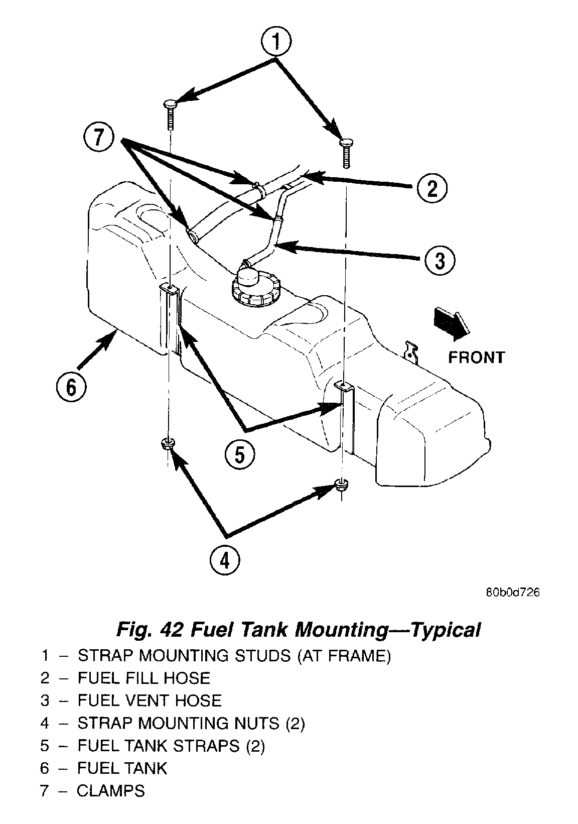
Fig. 42 Fuel Tank Mounting (Typical)
Pic 1
8. Remove fuel tank mounting strap nuts from mounting strap studs (Fig. 42). If equipped, remove fuel tank shield bolts.
9. Lower fuel tank only enough to allow access to top of tank. The 2 tank fittings (where rubber fuel fill and vent hose connections are made) must be positioned above tank level. Rotate tank slightly to allow these fittings to be above tank level.
WARNING: Wrap shop towels around hoses to catch any gasoline spillage.
10. While working over left rear tire/wheel, disconnect rubber fuel vent hose at fuel tank (Fig. 42) (vent hose is the smallest of 2 hoses). Position fuel siphoning/drain hose into this fitting at tank. Drain fuel into an approved portable holding tank or a properly labeled gasoline (or diesel fuel) safety container.
11. Disconnect rubber fuel fill hose at fuel tank (Fig. 42).
12. Gas Powered Engines:
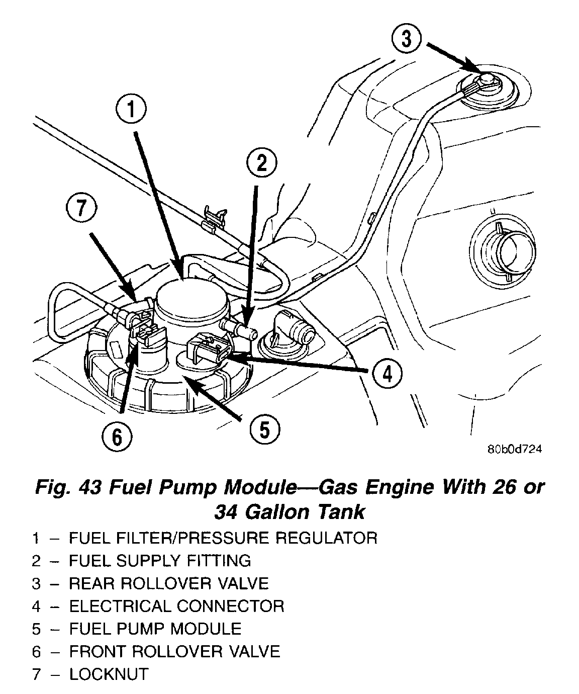
Fig. 43 Fuel Pump Module - Gas Engine With 26 Or 34 Gallon Tank
pic 2
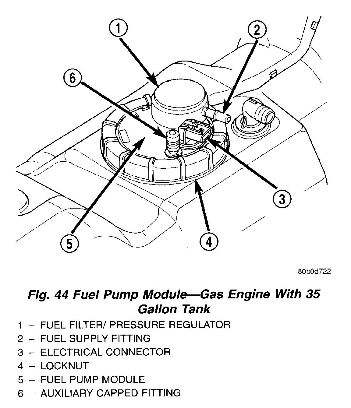
Fig. 44 Fuel Pump Module - Gas Engine With 35 Gallon Tank
pic 3
a. While working over left rear tire/wheel, disconnect wiring harness connector from electrical connector at top of fuel pump module (Fig. 43) or (Fig. 44).
b. If equipped with 26 or 34 gallon fuel tank, two EVAP lines are connected to rollover valves. Disconnect EVAP line from rollover valve at top of module (Fig. 43). Disconnect other EVAP line from rollover valve near rear of tank (Fig. 43).
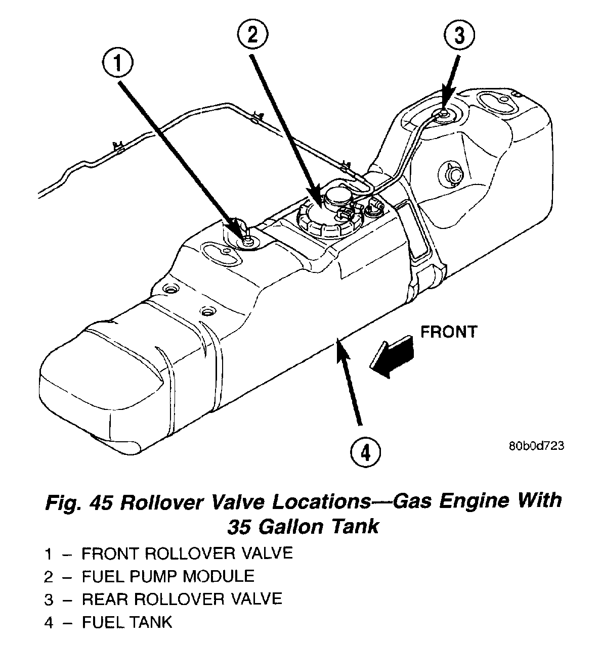
Fig. 45 Rollover Valve Locations - Gas Engine With 35 Gallon Tank
pic 4
c. If equipped with 35 gallon fuel tank, two EVAP lines are connected to rollover valves. Disconnect EVAP lines from rollover valves at top-front and top-rear of fuel tank (Fig. 45).
d. Disconnect fuel supply line at fuel filter/fuel pressure regulator supply fitting (Fig. 43) or (Fig. 44). Refer to Quick-Connect Fittings for procedures.
13. Diesel Powered Engines:
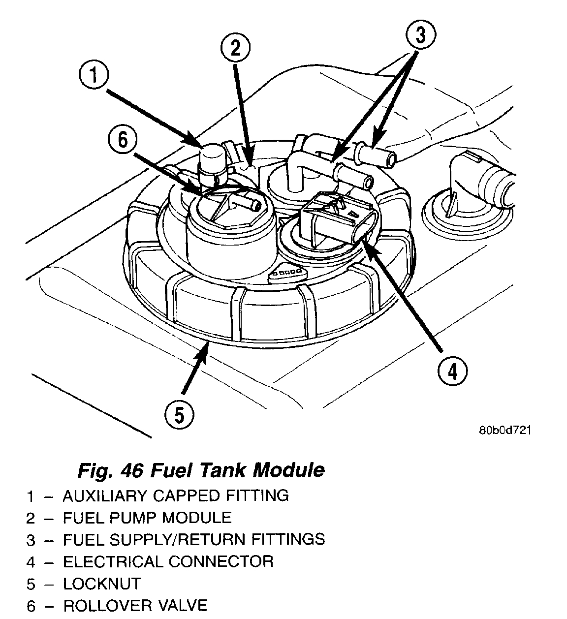
Fig. 46 Fuel Tank Module
pic 5
a. While working over left rear tire/wheel, disconnect wiring harness connector from electrical connector at top of fuel tank module (Fig. 46).
b. Disconnect fuel supply and fuel return lines at the fuel tank module fittings (Fig. 46). Refer to Quick-Connect Fittings for procedures.
14. Gasoline Engines: If fuel pump module removal is necessary, refer to Fuel Pump Module Removal/Installation. Diesel Engines: If fuel tank module removal is necessary, refer to Fuel Tank Module Removal/Installation.
INSTALLATION
1. Gasoline Engines: If fuel pump module is being installed, refer to Fuel Pump Module Removal/Installation. Diesel Engines: If fuel tank module is being installed, refer to Fuel Tank Module Removal/Installation.
2. Place fuel tank on top of transmission jack.
3. Install rubber fill and vent lines to tank. Tighten hose clamps to 2.3 Nm (20 in. lbs.) torque.
4. Raise tank into position while guiding fill and vent hoses to body. Raise tank only enough to allow access to top of tank.
5. Gas Powered Engines:
a. Connect electrical connector to fuel pump module.
b. Connect EVAP hoses at rollover valves.
c. Connect fuel supply line at fuel filter/fuel pressure regulator. Refer to Quick-Connect Fittings for procedures.
6. Diesel Powered Engines:
a. Connect electrical connector to fuel tank module.
b. Connect fuel supply and fuel return lines to fuel tank module fittings. Refer to Quick-Connect Fittings.
7. Connect two mounting straps and mounting strap nuts.
8. Tighten strap nuts to 41 Nm (30 ft. lbs.) torque. Do not over tighten retaining strap nuts.
9. Remove transmission jack.
10. Connect fuel filler tube assembly to body.
11. If equipped, connect grounding wire (strap) and screw.
12. Refill fuel tank and inspect all hoses and lines for leaks.
13. Connect negative battery cable(s) to battery(s).
________________________________________
Here are the directions for replacing the pump. The remaining pics correlate with the directions.
_______________________________________
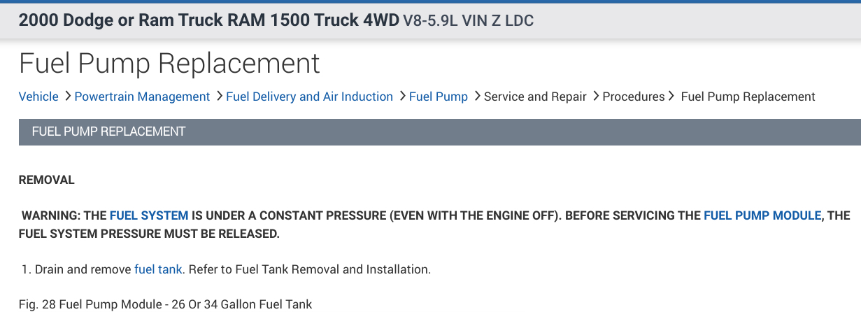
2000 Dodge or Ram Truck RAM 1500 Truck 4WD V8-5.9L VIN Z LDC
Fuel Pump Replacement
Vehicle Powertrain Management Fuel Delivery and Air Induction Fuel Pump Service and Repair Procedures Fuel Pump Replacement
FUEL PUMP REPLACEMENT
REMOVAL
WARNING: The fuel system is under a constant pressure (even with the engine off). Before servicing the fuel pump module, the fuel system pressure must be released.
1. Drain and remove fuel tank. Refer to Fuel Tank Removal and Installation.
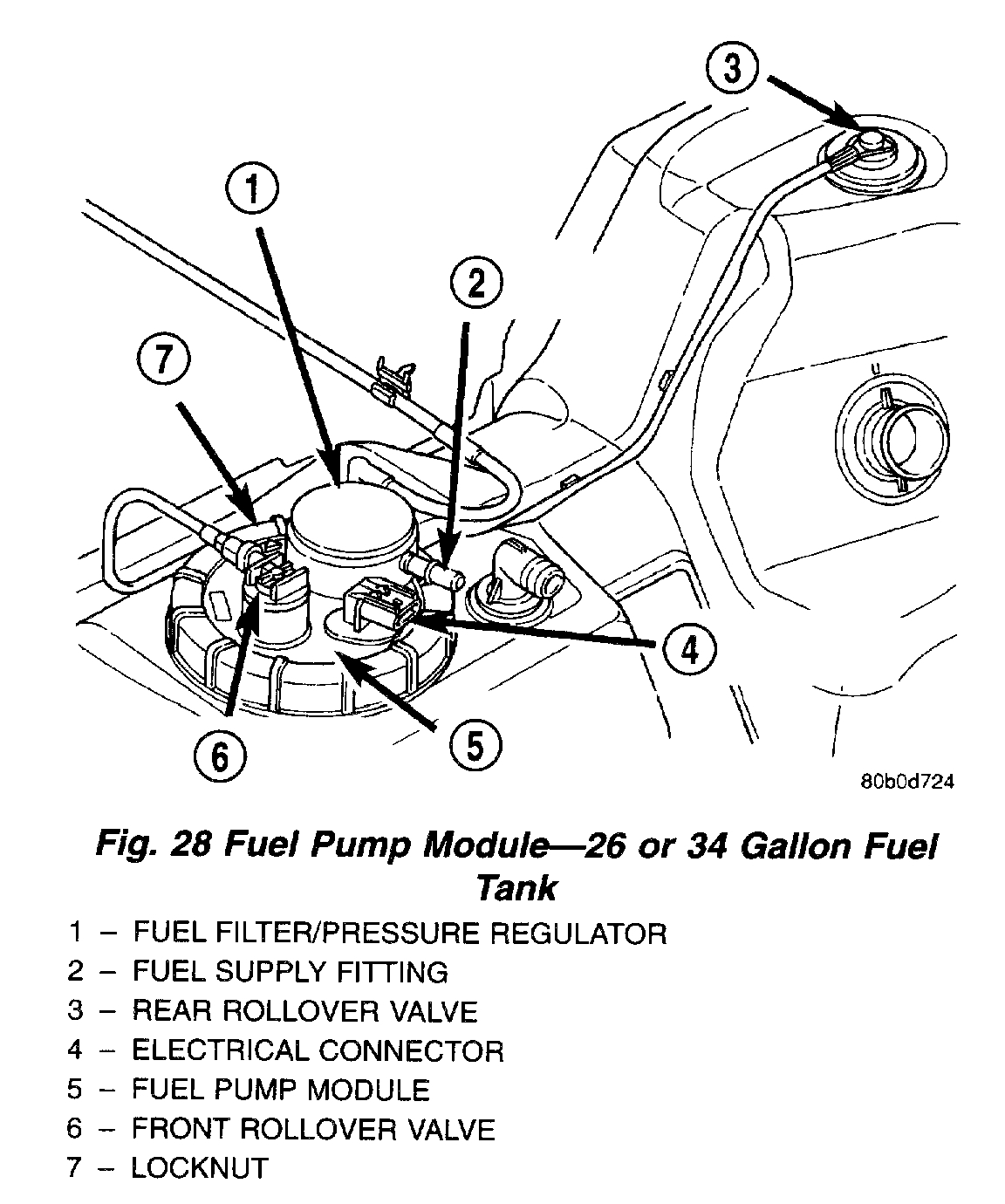
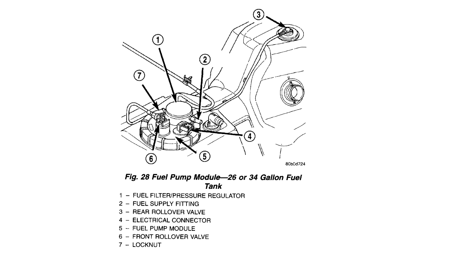
Fig. 28 Fuel Pump Module - 26 Or 34 Gallon Fuel Tank
pic 6
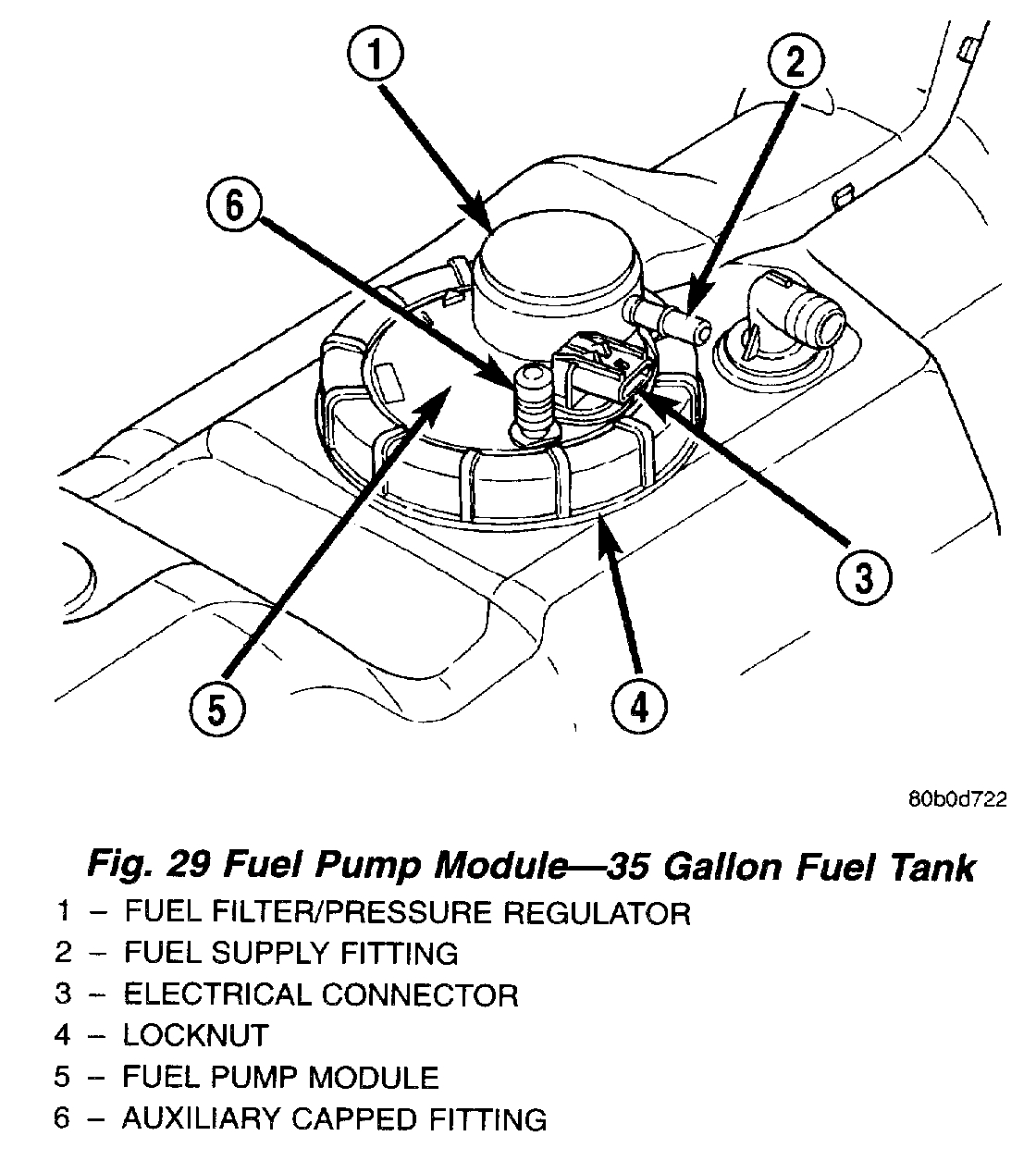
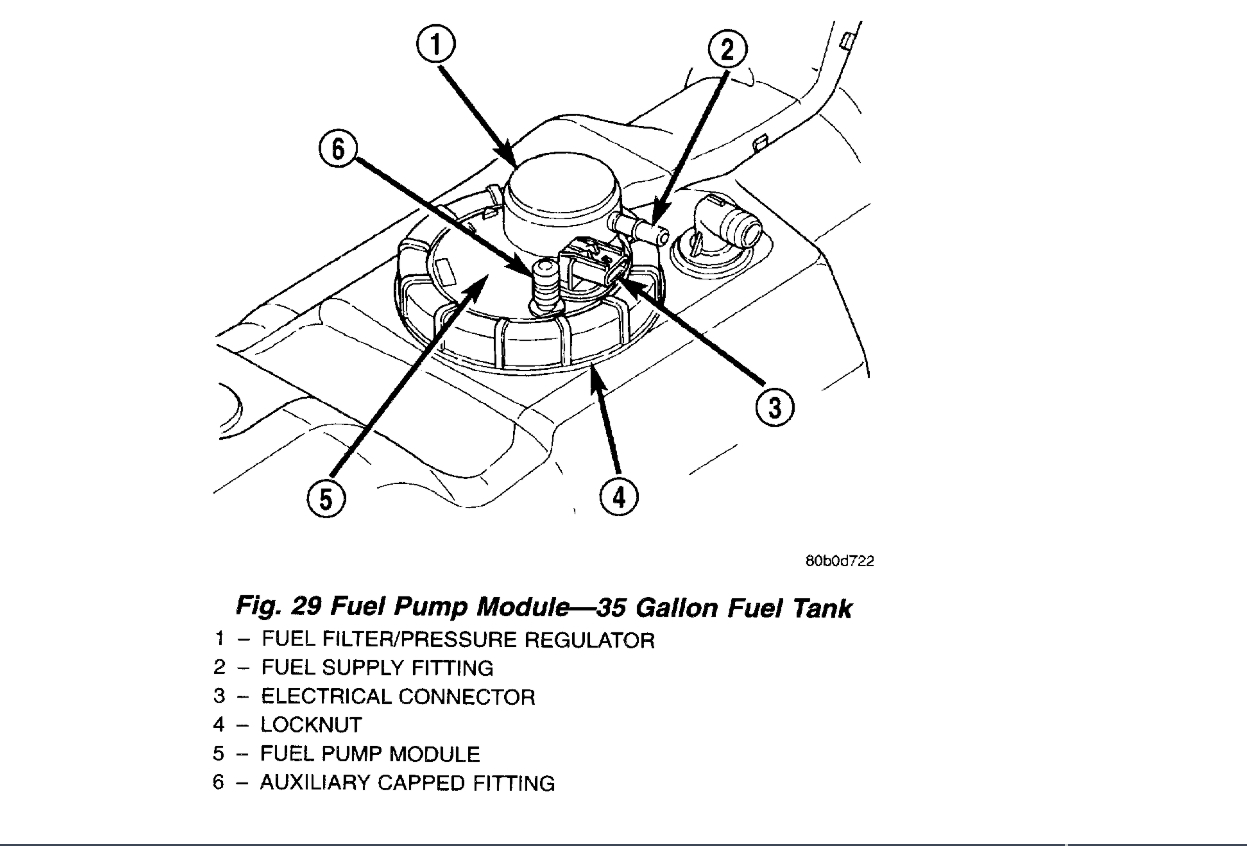
Fig. 29 Fuel Pump Module - 35 Gallon Fuel Tank
pic 7
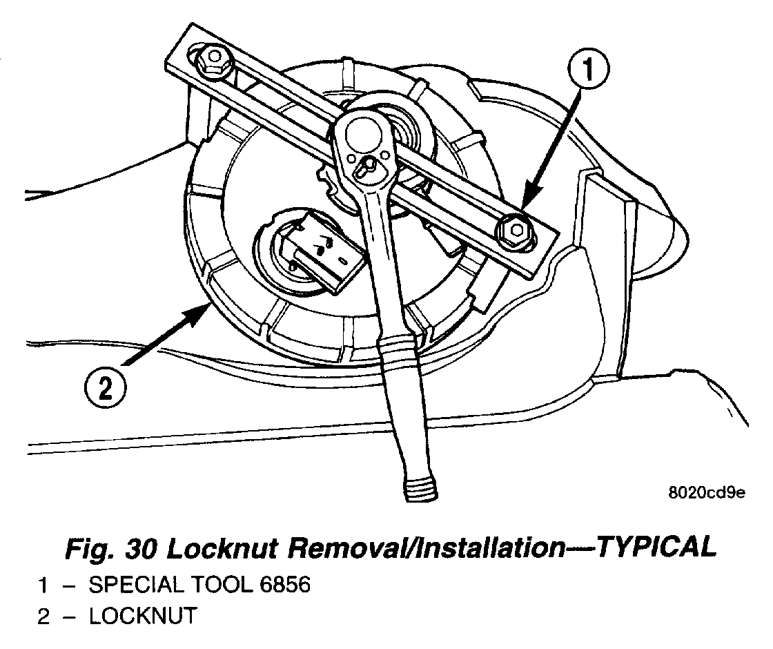
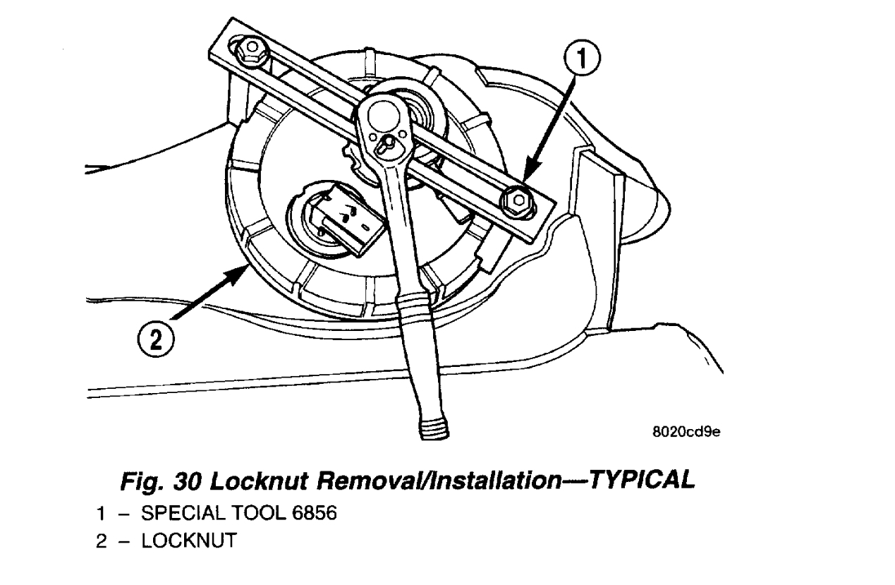
Fig. 30 Locknut Removal/Installation (Typical)
pic 8
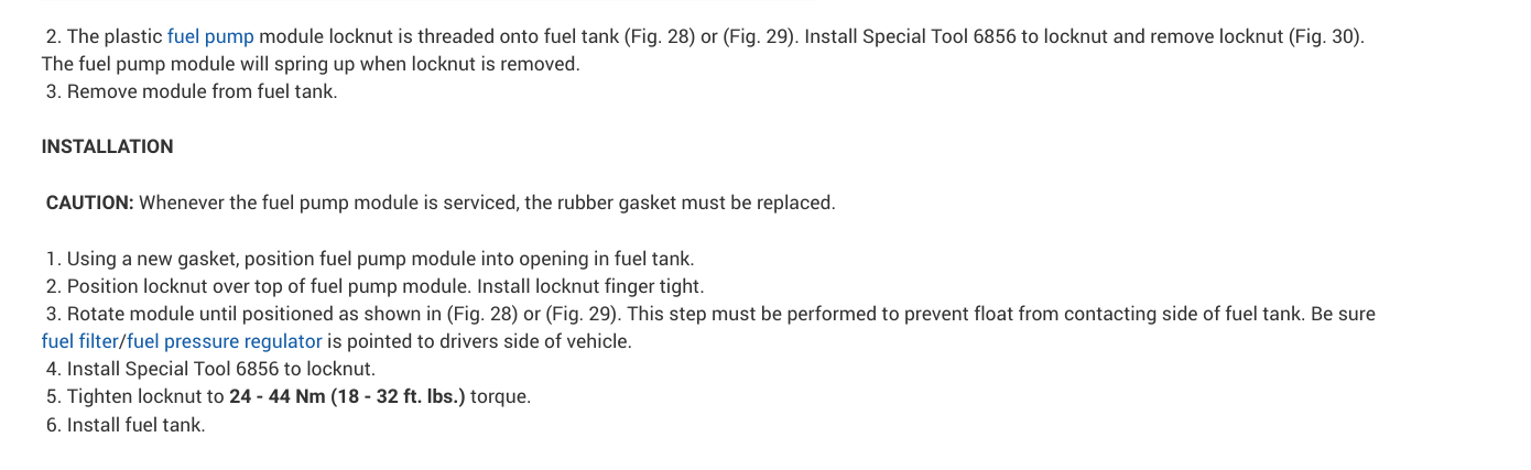
2. The plastic fuel pump module locknut is threaded onto fuel tank (Fig. 28) or (Fig. 29). Install Special Tool 6856 to locknut and remove locknut (Fig. 30). The fuel pump module will spring up when locknut is removed.
3. Remove module from fuel tank.
INSTALLATION
CAUTION: Whenever the fuel pump module is serviced, the rubber gasket must be replaced.
1. Using a new gasket, position fuel pump module into opening in fuel tank.
2. Position locknut over top of fuel pump module. Install locknut finger tight.
3. Rotate module until positioned as shown in (Fig. 28) or (Fig. 29). This step must be performed to prevent float from contacting side of fuel tank. Be sure fuel filter/fuel pressure regulator is pointed to drivers side of vehicle.
4. Install Special Tool 6856 to locknut.
5. Tighten locknut to 24 - 44 Nm (18 - 32 ft. lbs.) torque.
6. Install fuel tank.
______________________________
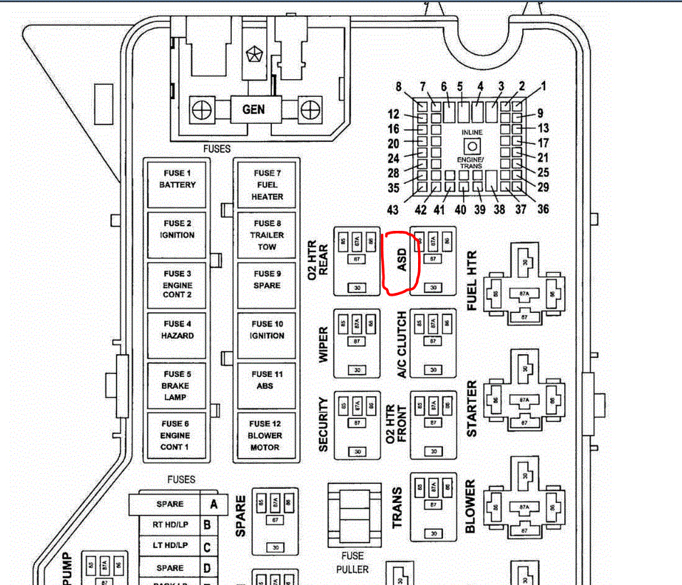
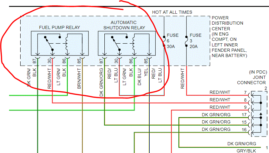
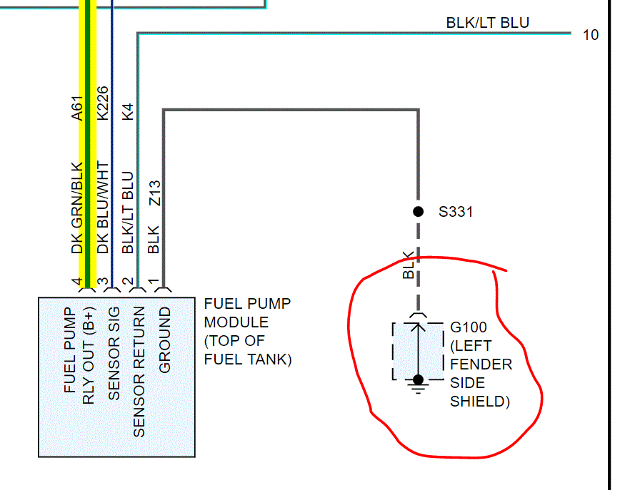
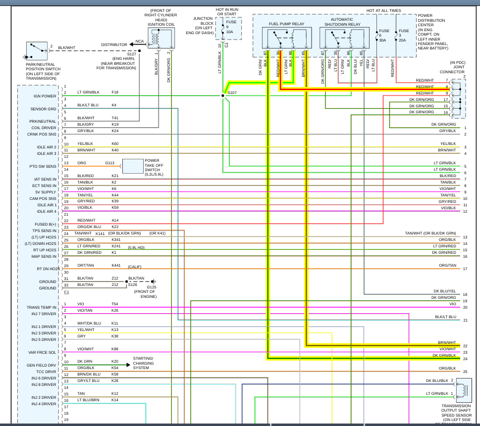
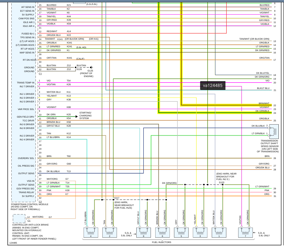
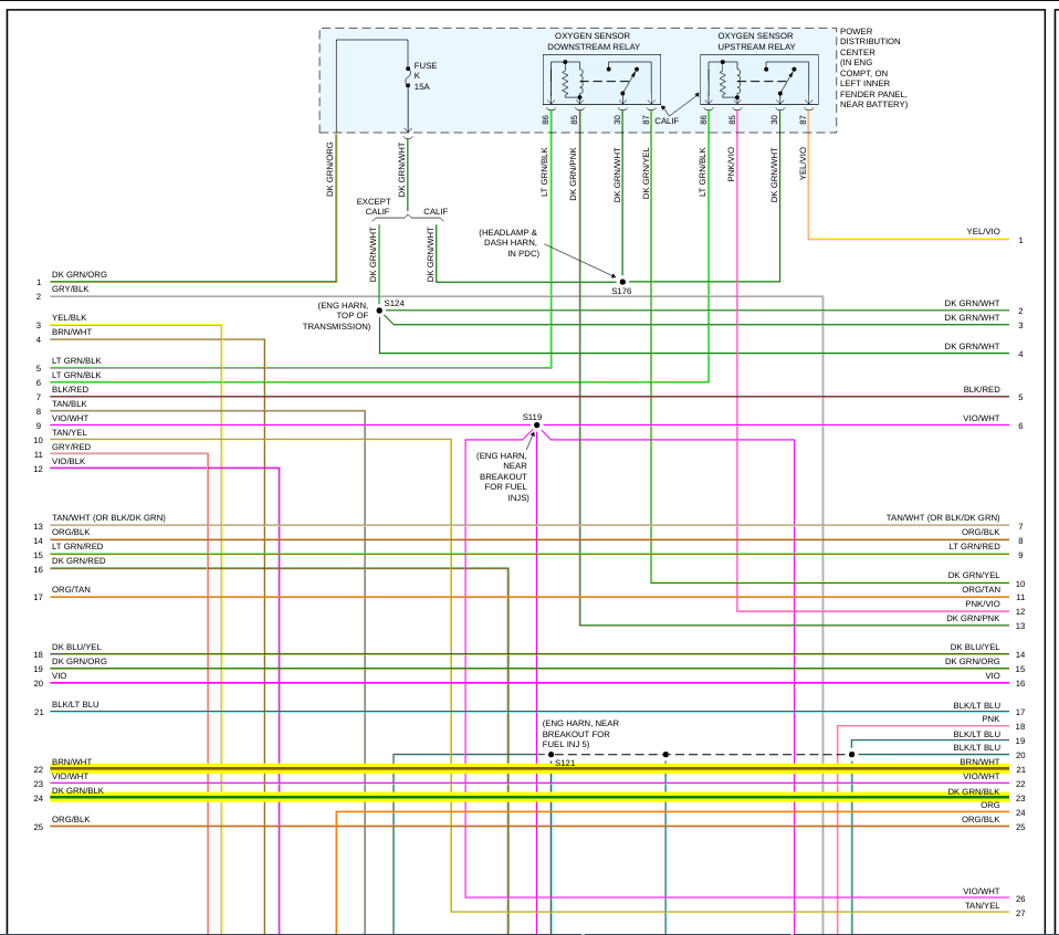
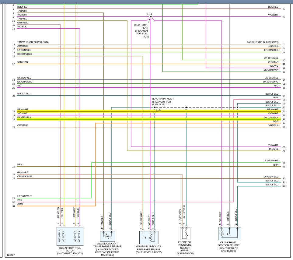
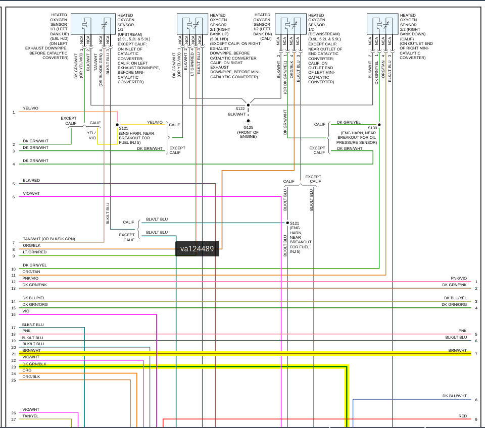
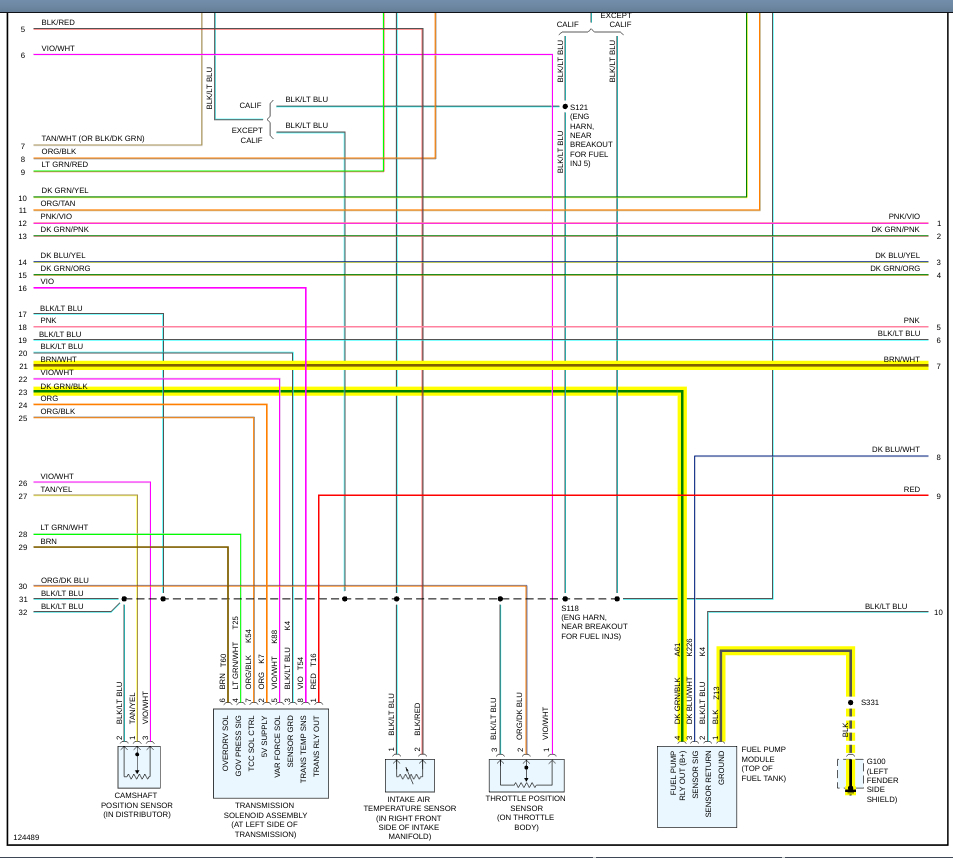
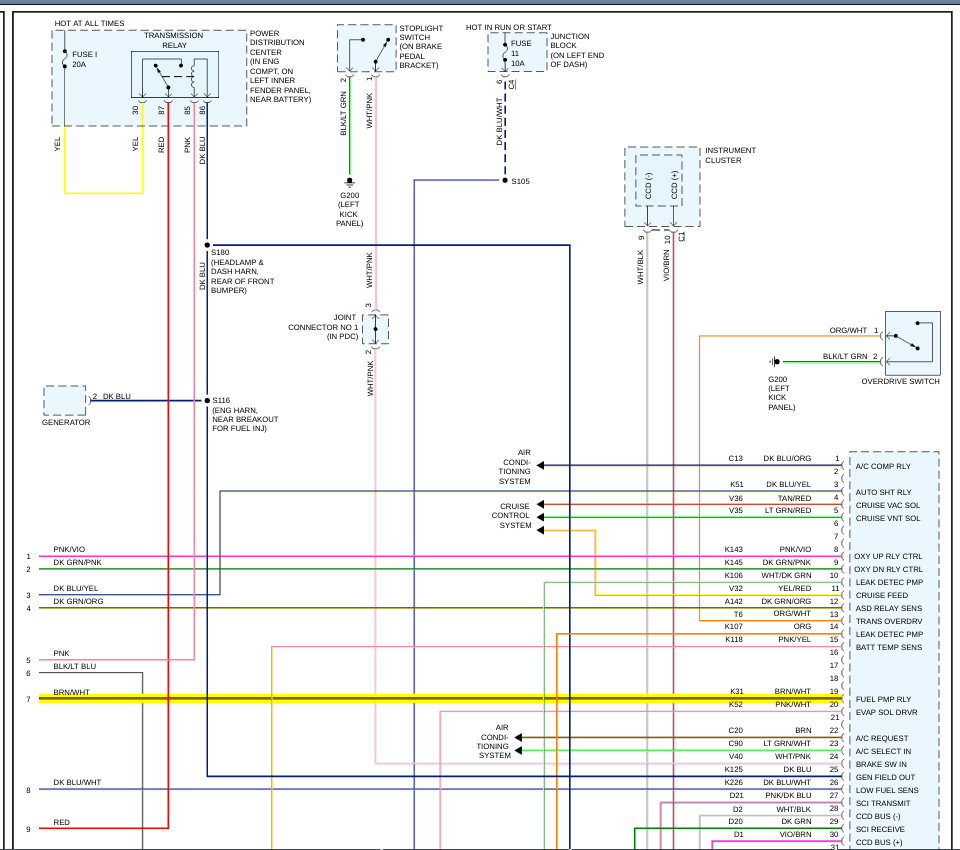
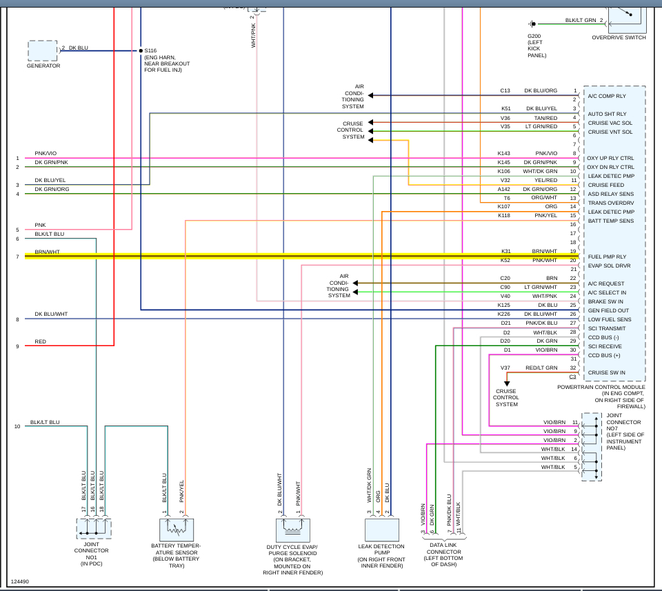
Keep in mind, this could also be a different issue. I would also check to see if there is spark to the plugs. This vehicle does have an ASD relay (auto shut down) See pic 9 and 10. I also attached a pic of the wiring at the pump. Make sure the ground is good as well and you should have power to the B+ wire when the key is first turned on to prime the system.
Let me know if this helps.
Joe
Images (Click to enlarge)
Jan 30, 2020 at 7:31 PM