Hi:
Because of the positioning, I don't think it will work. It's been awhile since I had one out, but if I recall, it's placed too far back on the tank. Plus, you would need to be perfectly aligned to it because there is no clearance. Also, if you have luck like I do, chances are you will cut through the wiring, fuel line, tank, or something.
_________________________________________
Here are the directions for removing the pump assembly and replacing just about every component on it. The attached pics correlate with the directions. The second set of directions are for removal and replacement of the fuel tank.
________________________________________
1998 Dodge Stratus V6-2.5L VIN H
Procedures
Vehicle Powertrain Management Fuel Delivery and Air Induction Fuel Tank Unit Service and Repair Procedures
PROCEDURES
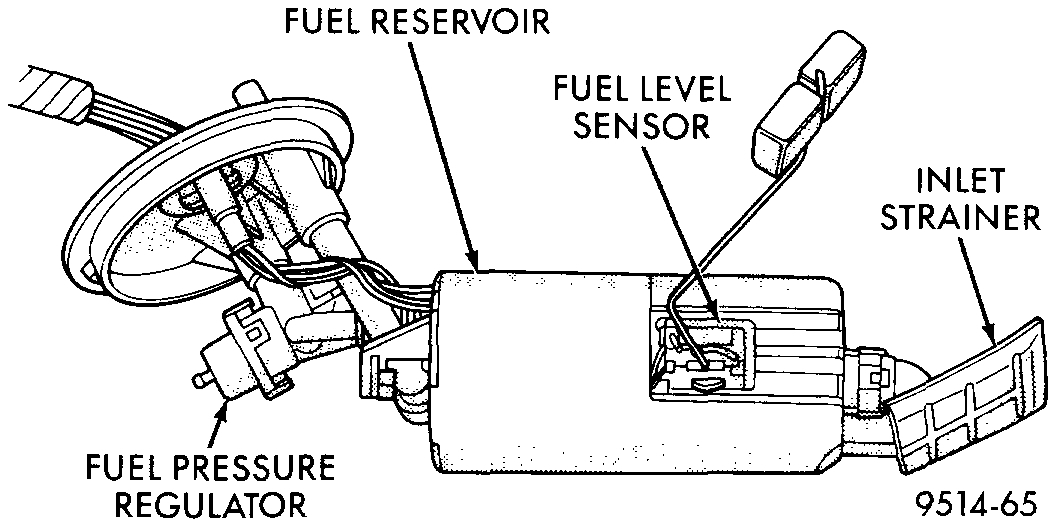
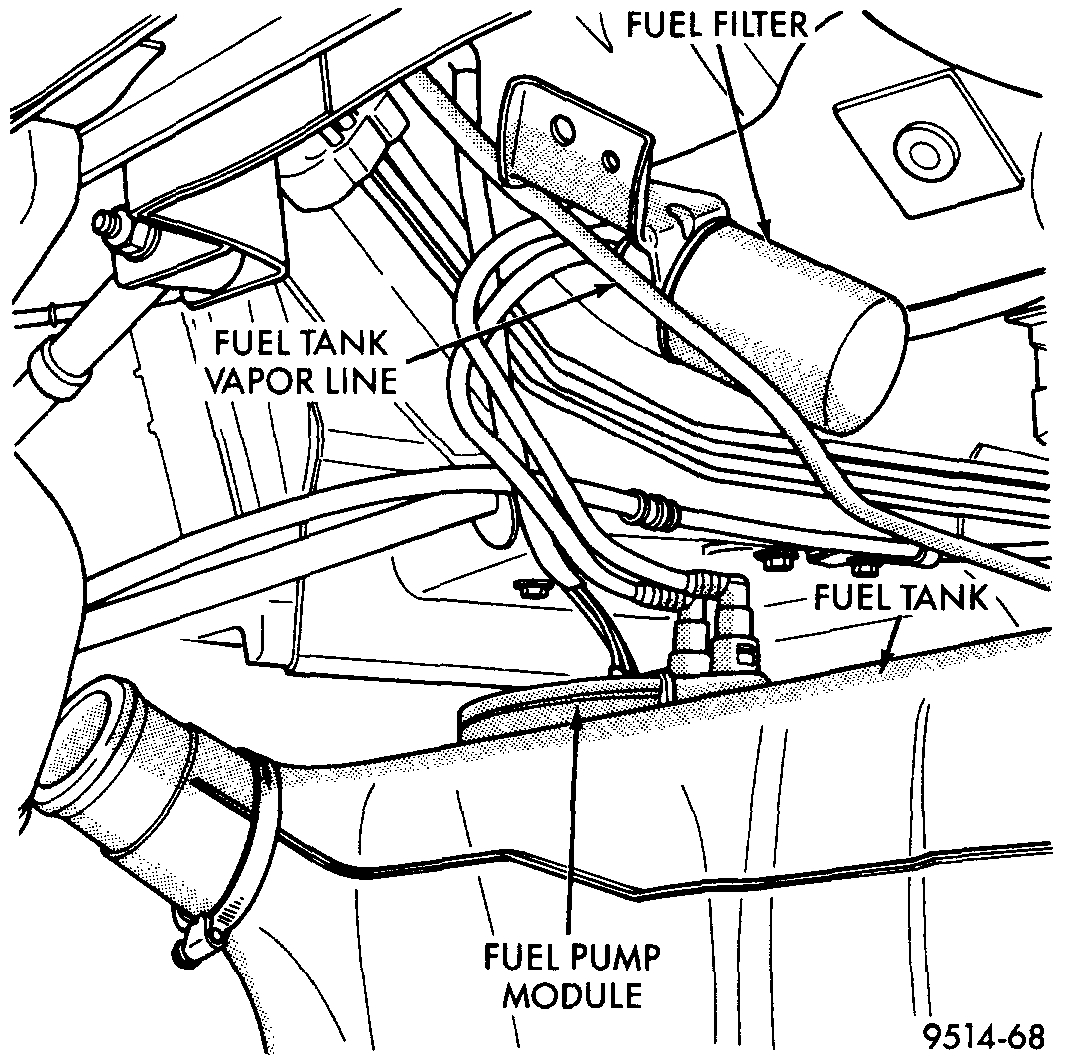
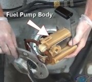
FUEL PUMP MODULE
The fuel pump module is installed in the top of the fuel tank Fig. 9. The fuel pump module contains the following:
- Electric fuel pump.
- Fuel pump reservoir
- Inlet strainer.
- Fuel pressure regulator.
- Fuel gauge sending unit
- Fuel supply and return line connections
The inlet strainer, fuel pressure regulator and level sensor are the only serviceable items. If the fuel pump requires service, replace the fuel pump module.
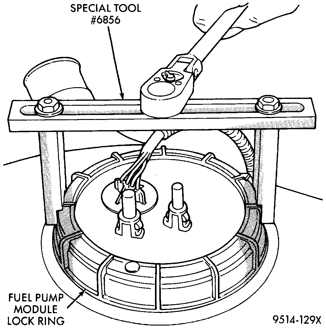
Fig. 10 Fuel Pump Module Locknut
Pic 1
ELECTRICAL PUMP REPLACEMENT
The electric fuel pump is not serviceable. If the fuel pump needs replacement, the complete fuel pump module must be replaced. Perform the Fuel Pressure Release procedure before servicing the fuel pump.
WARNING: Release fuel system pressure before servicing fuel system components. Service vehicles in well ventilated areas and avoid ignition sources. NEVER smoke while servicing the vehicle.
FUEL PUMP MODULE REMOVAL
1. Remove fuel filler cap and perform Fuel Pressure Release procedure.
2. Disconnect negative cable from auxiliary jumper terminal.
3. Remove fuel tank.
4. Disconnect fuel filter lines from fuel pump module.
5. Clean top of tank to remove loose dirt and debris.
6. Using Special Tool #6856 Fuel Pump Module Ring Spanner, remove locknut to release pump module Fig. 10.
WARNING: The fuel reservoir or the fuel pump module does not empty out when the tank is drained. The fuel in the reservoir may spill out when the module is removed.
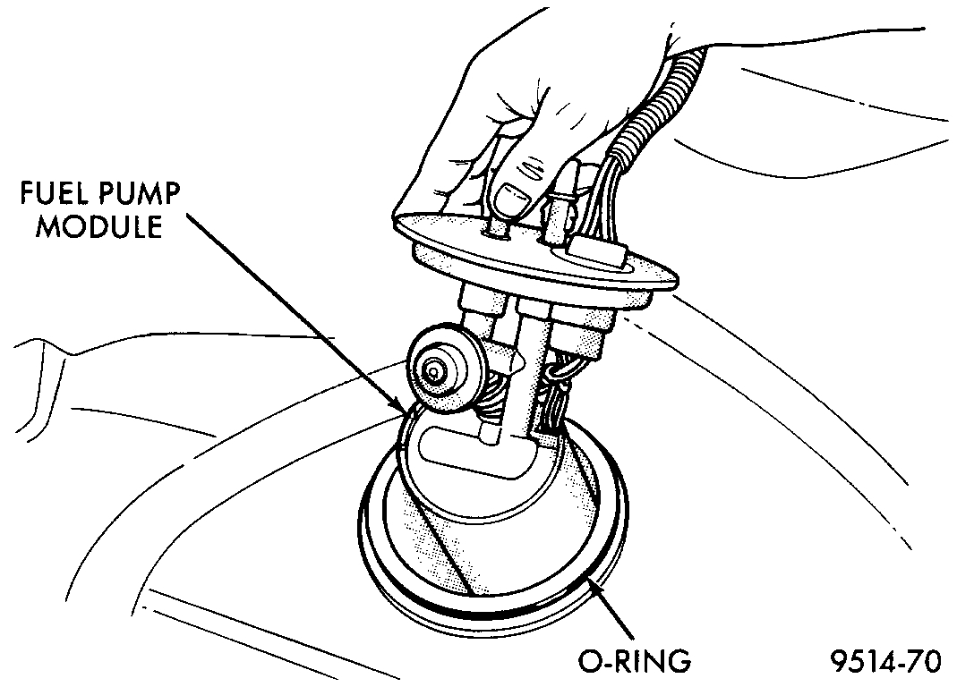
Fig. 11 Fuel Pump Module Removal
Pic 2
7. Remove fuel pump module and 0-ring from tank Fig. 11. Discard 0-ring.
FUEL PUMP MODULE INSTALLATION
1. Wipe seal area of tank clean. Place a new 0-ring on the ledge between the tank threads and the pump module opening.
2. Position fuel pump module in tank.
- Make sure the alignment tab on the underside of the pump module flange sits in the corresponding notch in the fuel tank.
CAUTION: Over tightening the pump lock ring may result in a leak.
3. While holding the pump module in position, install locknut. Tighten locknut to 61 Nm (45 ft lb) torque using special tool #6856.
4. Install fuel tank and fuel filter.
5. Fill fuel tank with clean fuel. Check for leaks.
6. Install negative cable to auxiliary jumper terminal.
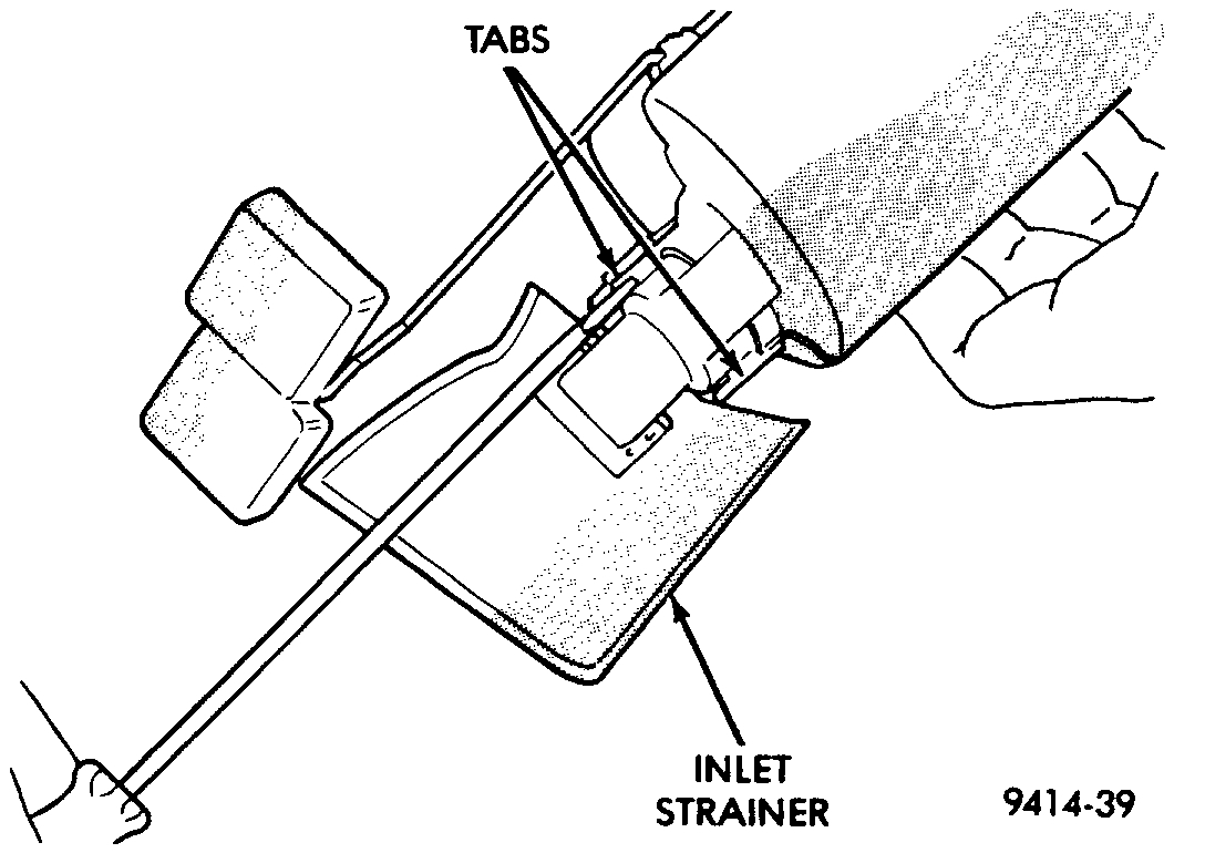
Fig. 12 Inlet Strainer Removal
Pic 3
FUEL PUMP INLET STRAINER SERVICE - REMOVAL
1. Remove fuel pump module.
2. Using a thin straight blade screwdriver, carefully pry back the locking tabs on fuel pump reservoir and remove the strainer Fig. 12.
3. Remove strainer 0-ring from the fuel pump reservoir body.
4. Remove any contaminants by washing the inside of the fuel tank.
INSTALLATION
1. Lubricate the strainer 0-ring with clean motor oil.
2. Insert strainer 0-ring into outlet of strainer so that it sits evenly on the step inside the outlet.
3. Push strainer onto the inlet of the fuel pump reservoir body. Make sure the locking tabs on the reservoir body lock over the locking tangs on the strainer.
4. Install fuel pump module.
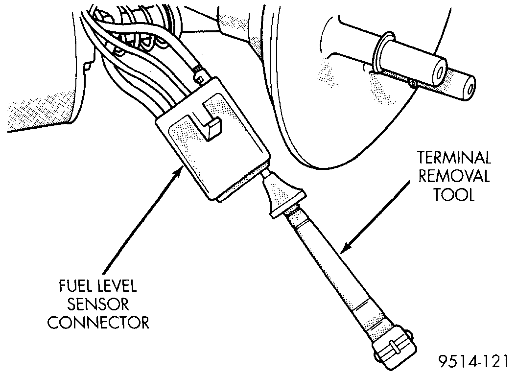
Fig. 14 Fuel Pump/Level Sensor Electrical Connector
Pic 4
FUEL LEVEL SENSOR
The fuel level sensor attaches to the side of the fuel pump module. Remove the fuel pump module to replace the fuel level sensor.
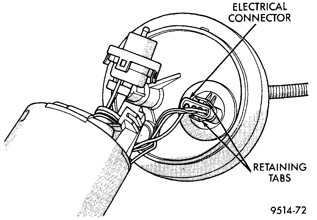
Fig. 14 Fuel Pump/Level Sensor Electrical Connector
pic 5
NOTE: Remove fuel pump module to gain access to this sensor.
REMOVAL
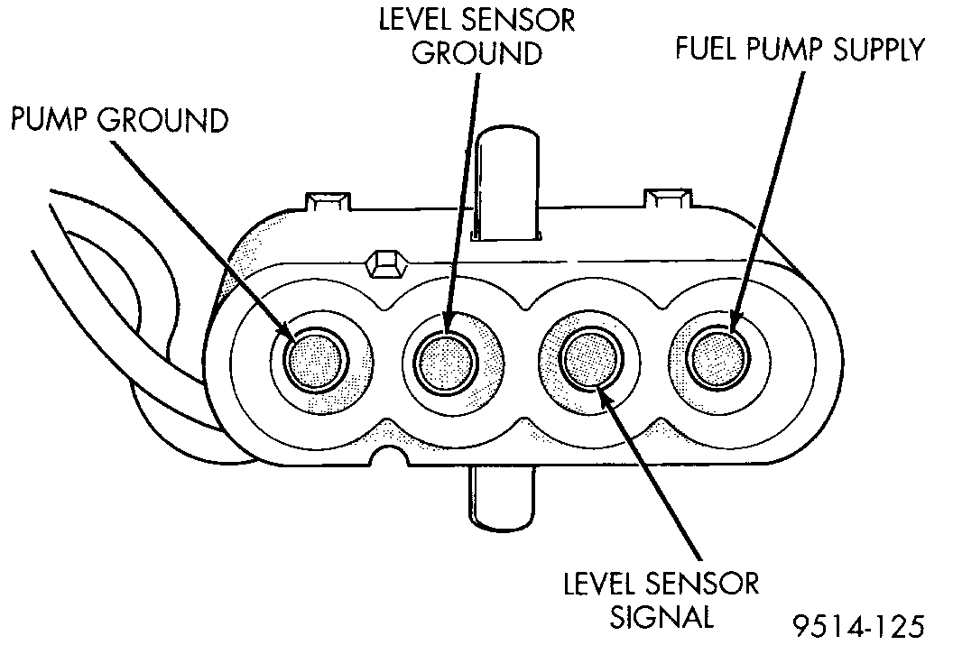
1. Depress retaining tab and remove fuel pump/level sensor connector from bottom of fuel pump module electrical connector Fig. 14.
Fig. 15 Terminal Removal Tool
Pic 6
2. Using Special Tool #C-4334 terminal remover or equivalent, remove terminals from level sensor connector Fig. 15.
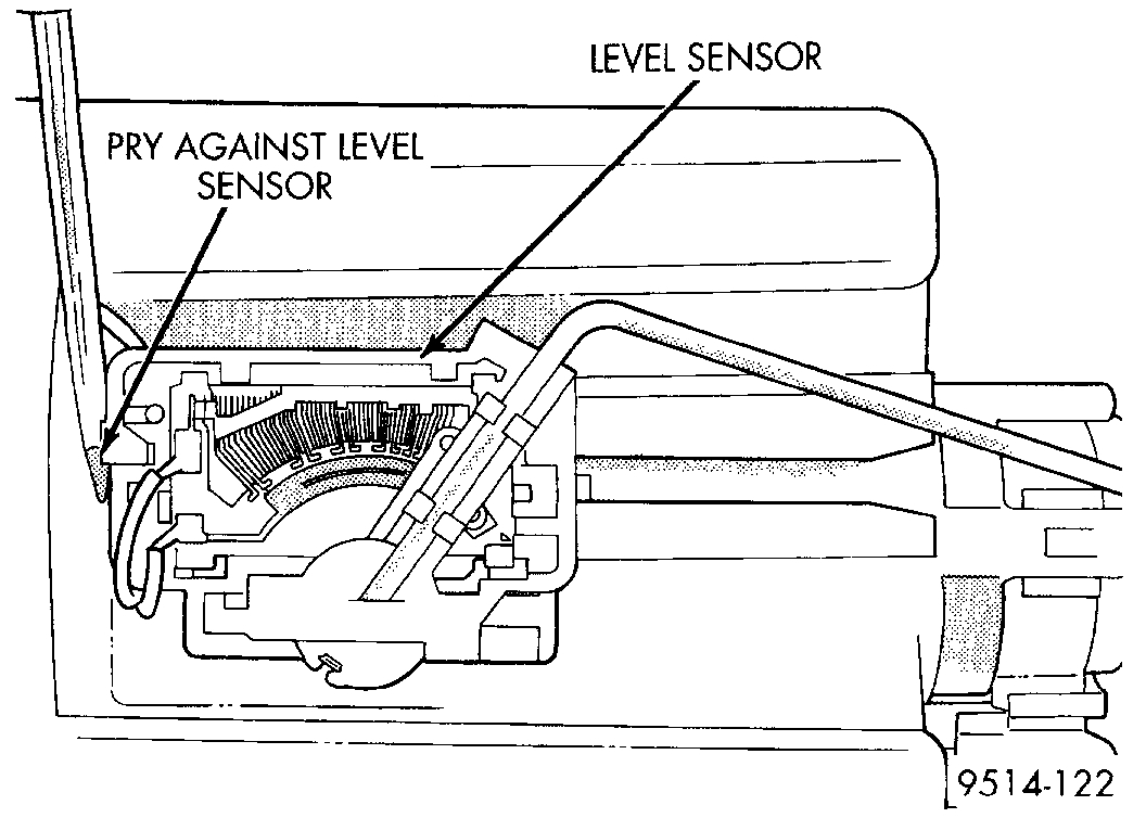
Fig. 16 Loosening Level Sensor
Pic 7
3. Insert a screwdriver between the fuel pump module and the top of the level sensor housing Fig. 16. Push level sensor down slightly.
4. Slide level sensor wires through opening fuel pump module.
5. Slide level sensor out of installation channel in module.
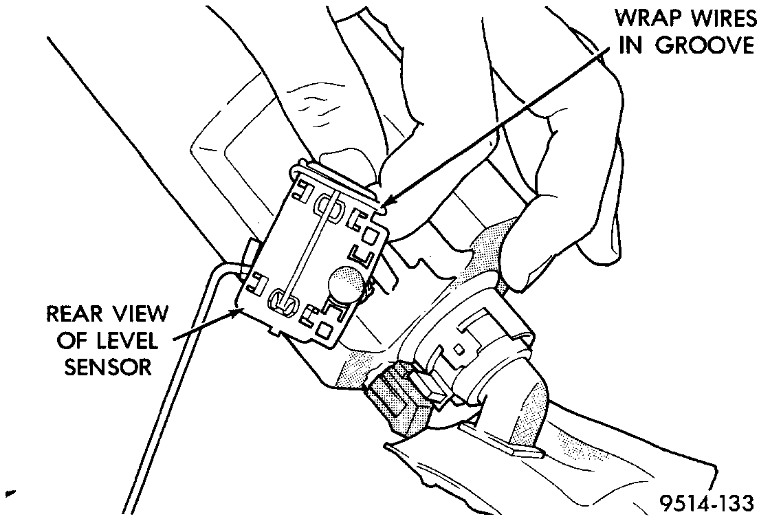
Fig. 17 Groove In Back Side Of Level Sensor
pic 8
INSTALLATION
1. Insert level sensor wires into bottom of opening in module.
2. Wrap wires into groove in back of level sensor Fig. 17.
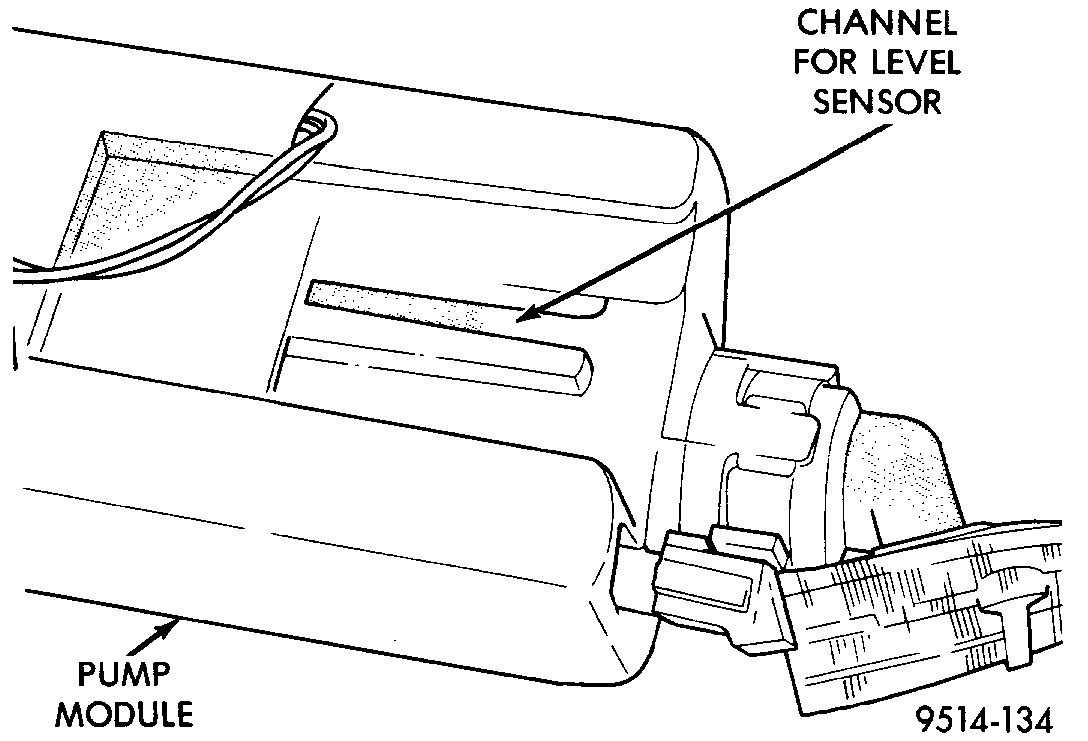
Fig. 18 Installation Channel
pic 9
3. While feeding wires into guide grooves, slide level sensor up into channel until it snaps into place Fig. 18. Ensure tab at bottom of sensor locks in place.
Fig. 19 Fuel Pump/Level Sensor Electrical Connector
pic 10
4. Install level sensor wires in connector.
- Push the wires up through the connector and then pull them down until they lock in place.
- Ensure signal and ground wires are installed in the correct position Fig. 19.
5. Install locking wedge on connector.
6. Push connector up into bottom of fuel pump module electrical connector.
7. Install fuel pump module.
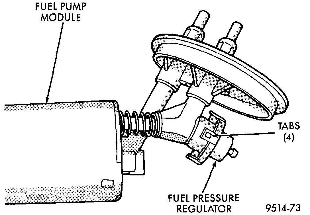
Fig. 20 Fuel Pressure Regulator
pic 11
pic 12
FUEL PRESSURE REGULATOR
The fuel system uses a nonadjustable pressure regulator that maintains fuel system pressure at approximately 338 kPa (49 psi). The fuel pressure regulator contains a diaphragm, calibrated spring and a fuel return valve. The spring pushes down on the diaphragm and closes off the fuel return port.
System fuel pressure reflects the amount of fuel pressure required to open the return port.
The fuel pressure regulator is part of the fuel pump module Fig. 20. Remove the fuel pump module from the fuel tank for access to the fuel pressure regulator.
NOTE: Remove the fuel pump module from the fuel tank for access to the fuel pressure regulator.
REMOVAL
1. Spread tangs on pressure regulator retainer Fig. 20.
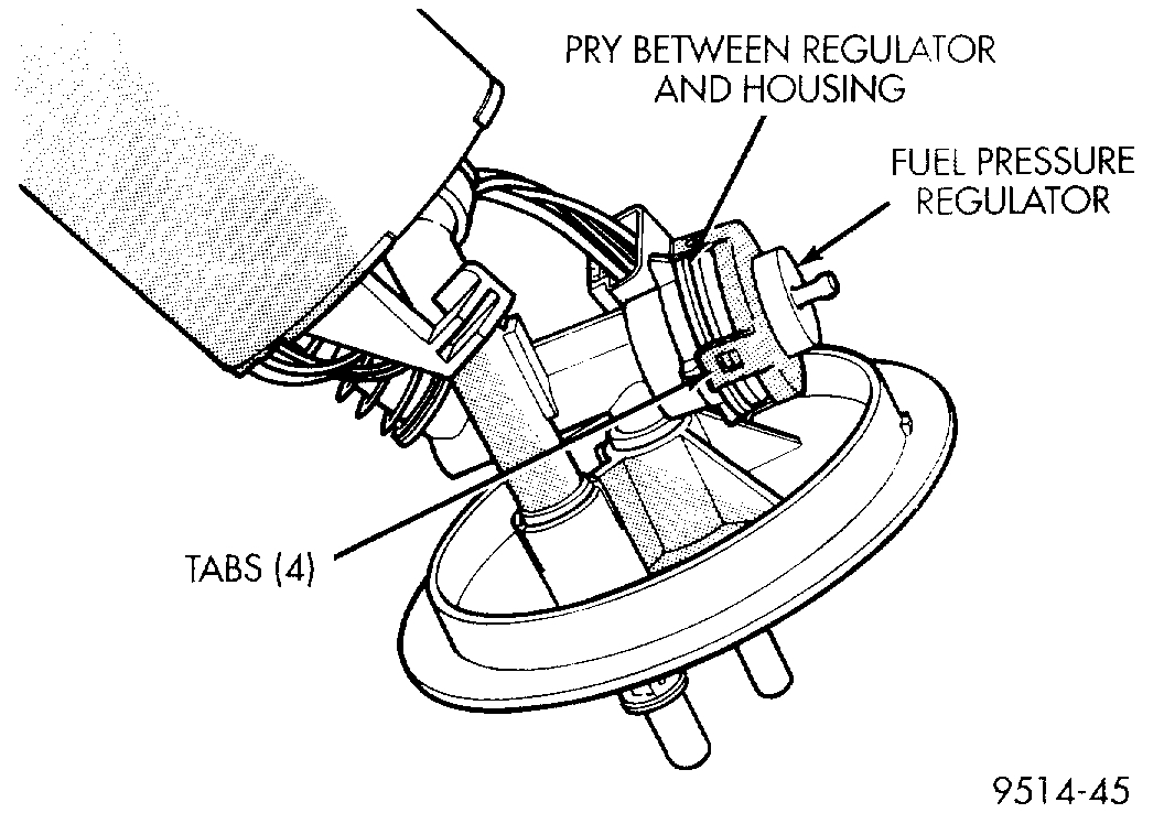
Fig. 21 Fuel Pressure Regulator Removal
pic 13
Pic 14
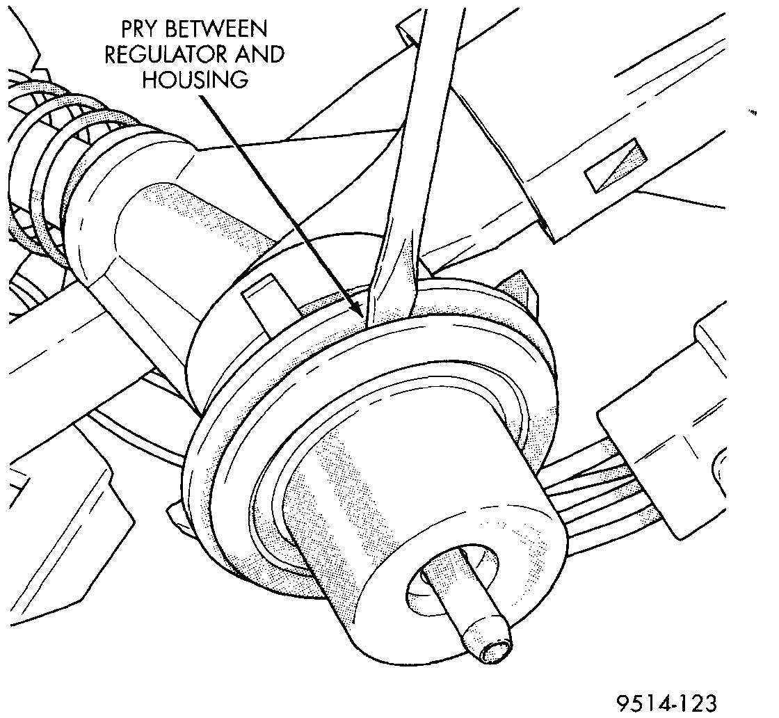
2. Pry fuel pressure regulator out of housing Fig. 21.
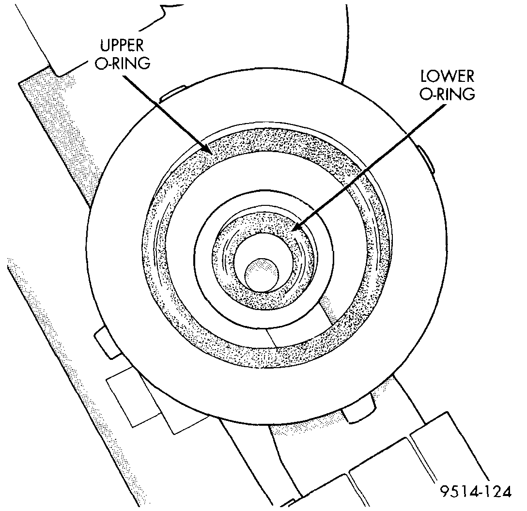
3. Ensure both upper and lower 0-rings are removed from regulator housing and discarded.
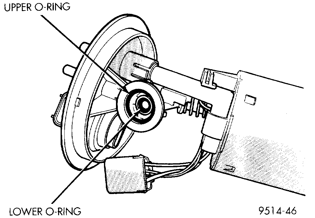
Fig. 22 Fuel Pressure Regulator O-Rings
pic 15
INSTALLATION
1. Lightly lubricate the 0-rings with engine oil and place them into opening in regulator housing Fig. 22.
2. Push regulator into opening in pump module.
3. Fold tangs on regulator retainer over tabs on housing.
__________________________________________
Here are the directions for removal and replacement of the fuel tank. The remaining pics correlate with the directions.
_________________________________________
1998 Dodge Stratus V6-2.5L VIN H
Fuel Tank Replacement
Vehicle Powertrain Management Fuel Delivery and Air Induction Fuel Tank Service and Repair Procedures Fuel Tank Replacement
FUEL TANK REPLACEMENT
Fig. 1 Fuel Tank Drain Plug
Pic 16
WARNING: Release fuel system pressure before servicing fuel system components. Service vehicles in well ventilated areas and avoid ignition sources. NEVER smoke while servicing the vehicle.
1. Release fuel system pressure.
2. Disconnect negative cable from auxiliary jumper terminal.
3. From inside trunk, disconnect pump wiring jumper from main body harness. The 4 pin connector is located under the trunk mat on the left side of trunk near the base of the shock tower. Locate body grommet for jumper near base of rear seat. Push grommet out and feed jumper completely through hole in body.
4. Remove fuel cap slowly to release tank pressure.
5. With vehicle on a hoist, drain fuel from tank. Support fuel tank with a support such as a transmission jack stand.
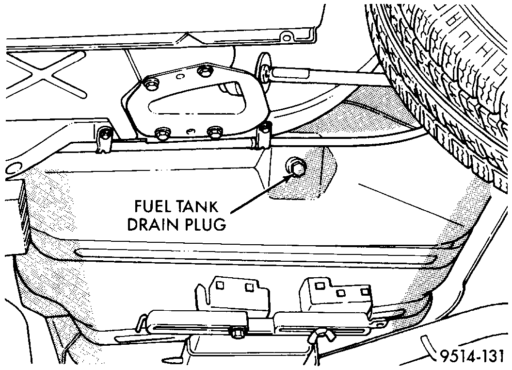
6. Position a fuel approved container, with a capacity of at least 16 gallons, under the drain plug located on the bottom left edge of the tank.
7. Remove drain plug and allow fuel to drain (Fig. 1).
WARNING: Drain plug must be installed at this time as there will be 1 to 2 gallons of fuel left in the tank.
8. When tank is no longer draining, install drain plug. Tighten plug to 32 in. Lbs.
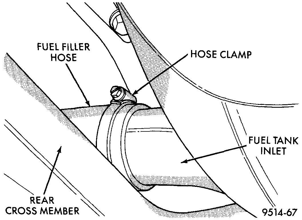
WARNING: There may be fuel in the fill tube. Remove hose carefully to reduce fuel splash.
Fig. 2 Fuel Filler Hose Clamp
pic 17
9. Disconnect fuel tank from rubber fill hose (Fig. 2).
Fig. 3 Fuel Tank Removal
Pic 18
WARNING: Wrap shop towels around hoses to catch any gasoline spillage.
10. Position transmission jack under fuel tank assembly.
11. Remove bolts and fuel tank straps. Passenger side first/
Fig 39 EVAP Components
Pic 19
12. Lower fuel tank and remove the purge line and vent line (Fig 39).
13. Disconnect fuel lines from fuel pump module. These are quick connect fittings (Fig. 3).
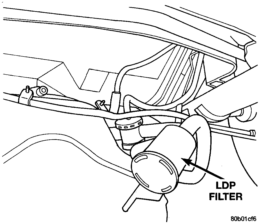
14. Remove hoses from EVAP canister.
15. Disconnect electrical connector for Leak Detection Pump (LDP).
16. Remove tank from vehicle. Slide tank forward during removal to allow fill neck to clear suspension cross-member.
INSTALLATION
1. Position fuel tank on transmission jack.
2. Raise tank into position.
3. Connect vapor line to rollover valve.
4. Install EVAP hoses and lines.
5. Connect LDP and fuel pump electrical connector.
6. Install pump module harness grommet into body.
7. Connect chassis fuel tube to fuel filter.
8. Connect fuel fill tube to tank inlet. Tighten hose clamp to 3.5 Nm (31 in. Lbs.) Torque.
9. Position fuel filter and fuel tank straps.
- Install the front bolts first and then the rear bolts.
- Tighten fuel tank strap bolts to 23 Nm (250 in. Lbs.) Torque.
- Remove transmission jack.
- Ensure straps are not twisted or bent.
10. Lower vehicle.
11. Connect fuel pump module connector -- inside of vehicle.
12. Fill fuel tank, install filler cap, and connect battery cable.
CAUTION: When using the ASD Fuel System Test, the ASD relay remains energized for either 7 minutes, until the test is stopped, or until the ignition switch is turned to the Off position.
13. Use the DRB Scan Tool-ASD Fuel System Test to pressurize the fuel system. Check for leaks.
Let me know if this helps.
Joe
Images (Click to make bigger)
Saturday, November 16th, 2019 AT 7:05 PM