Hello .. thanks for the donation .. much appreciated
Hope this helps .. let me know
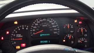
WARNING LIGHT INDICATORS
The Anti-Lock Brake System (ABS) uses an Amber ABS warning light to alert driver that ABS function has been disabled. Normal power assisted braking remains functional, but wheels can lock during a panic stop if Amber ABS warning light is on. There are 3 conditions which will illuminate ABS warning light:
ABS system malfunction.
Low brake fluid level detected by Anti-Lock Brake Control Module (ABCM). Red BRAKE warning light will also be illuminated.
Wiring problem in low brake fluid level detection circuit. Red BRAKE warning light will also be illuminated.
If ABCM detects that Amber ABS warning light cannot be illuminated, Red BRAKE warning light will be illuminated in its place and Diagnostic Trouble Code (DTC) C1220 will be stored in memory.
SPEEDOMETER/ODOMETER INOPERATIVE
Ensure instrument cluster and Vehicle Speed Sensor (VSS) connectors are properly connected. Repair connections as necessary and retest system. If all connections are okay, go to next step.
Road test vehicle and observe odometer and speedometer operation. If odometer operates and speedometer pointer does not move, replace speedometer and retest system. If symptoms are not as described, go to next step.
If speedometer pointer operates and odometer is inoperative, replace speedometer and retest system. If symptoms are not as described, go to next step.
Remove VSS. Inspect VSS drive and driven gears. If either gear is damaged, replace damaged gear and retest system. If VSS gears are okay, go to next step.
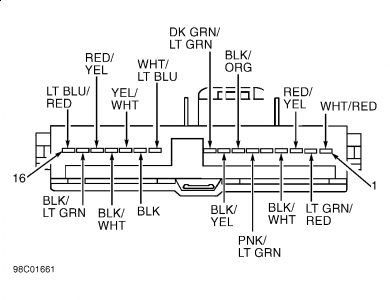
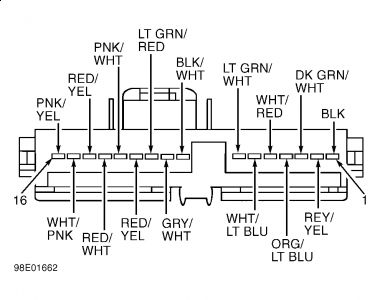
Remove instrument cluster. See INSTRUMENT CLUSTER under REMOVAL & INSTALLATION. Disconnect instrument cluster connector C240. See Fig. 5 and Fig. 6 . Turn ignition on. Measure voltage between ground and instrument cluster connector C240 terminal No. 2 (Red/Yellow wire). If battery voltage is present, go to next step. If battery voltage is not present, repair open in Red/Yellow wire between instrument cluster and instrument panel fuse panel. Retest system.
Turn ignition off. Measure resistance between ground and instrument cluster connector C240 terminal No. 8 (Black/White wire). If resistance is less than 5 ohms, go to next step. If resistance is more than 5 ohms, repair open in Black/White wire.
Disconnect instrument cluster connector C239. Measure voltage between ground and instrument cluster connector C239 terminal No. 15 (Black/Light Green wire). If battery voltage is present, go to next step. If battery voltage is not present, repair open in Black/Light Green wire between instrument cluster and instrument panel fuse panel. Retest system.
Disconnect VSS connector. Measure resistance of Dark Green/White wire between instrument cluster connector C240 terminal No. 14 and VSS connector. If resistance is less than 5 ohms, go to SPEEDOMETER/ODOMETER INACCURATE symptom test. If resistance is more than 5 ohms, repair open in Dark Green/White wire. Retest system.
Friday, March 6th, 2009 AT 6:38 AM