HEATER SYSTEM -1998 Ford
Removal & Installation
Disconnect negative battery cable. Drain cooling system. Remove instrument panel. See INSTRUMENT PANEL.
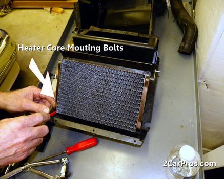
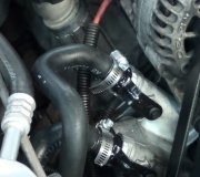
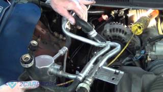
Disconnect heater hoses at heater core. Remove A/C plenum demister adapter.
Disconnect vacuum line.
Remove heater core bracket.
Remove 13 plenum assembly top screws and remove plenum top.
Remove temperature blend door assembly. Remove heater core from plenum.
To install, reverse removal procedure.
INSTRUMENT PANEL
1. Disable air bag system.
Move automatic transmission shift lever to "1" position (if equipped). Carefully pry to release 4 clips and remove steering column opening cover. Remove fuse door. Position hood latch and parking brake release handles aside.
2. Remove instrument panel floor duct panel. Remove lower instrument panel steering column cover. Remove left and right side door scuff plates. Remove left and right side cowl side trim panels. Disconnect brake on/off switch connector. Disconnect radio and Generic Electronic Module (GEM)/Central Timer Module (CTM) ground connections.
3. Disconnect 3 instrument panel main harness connectors. Remove firewall wiring harness from inside left side of engine compartment. Pull bulkhead electrical connector handle and disconnect harness. Disconnect both air bag diagnostic monitor connectors located behind right side of instrument panel. Disconnect inertia fuel shutoff switch connector located behind right side of instrument panel.
4. Disconnect right side ground connections. Disconnect electronic blend door motor connector and heater control panel vacuum line connector. Remove instrument panel steering column opening cover support. Disconnect all electrical connectors from steering column. Remove 4 steering column support nuts and lower steering column.
5. Disconnect radio antenna cable and remove radio. Remove instrument panel relay cover. Open glove box and release both door stops. Remove passenger side air bag module. Remove right side assist handle and windshield molding. Remove instrument panel bolt under left side of glove box.
6. Remove 2 instrument panel bolts behind passenger side air bag module opening. Remove 2 upper instrument panel bolts and bolt on relay bracket. Remove lower instrument panel bolt on left side of cigarette lighter.
7. Remove 2 lower instrument panel nuts located on either corner of instrument panel. Remove instrument panel bolt under center of steering column. Remove 2 instrument panel bolts on bottom left and right sides of instrument cluster opening.
8. Disconnect air bag sliding contact connectors and anti-theft sensor connector. Disconnect steering column connectors. Remove instrument panel from right side floor brace. Remove instrument panel.
9. To install, reverse removal procedure. Align and position instrument panel with clips in sheet metal. Tighten steering column mounting nuts to 10-13 ft. Lbs. (13.5-17.6 N.M).
Tuesday, January 13th, 2009 AT 8:54 PM