Sure here is the instructions and diagrams in the images below that shows you how to do the job, you will need a large C clamp to help do the repair.
DISASSEMBLY
1. Remove instrument panel cover and reinforcement from vehicle.
2. Unscrew and remove tilt wheel handle and shank.
3. Remove three screws and lower steering column shroud.
4. Remove steering column lock cylinder.
5. Remove upper steering column shroud.
6. Using door trim removal tool, remove clock spring electrical connectors from bend bracket.
7. Using door trim removal tool, disconnect two wire harness clips from steering column.
8. Remove key warning chime contact and antitheft contact from ignition lock cylinder pocket of lock cylinder housing.
9. Remove clock spring by pushing snap back at 6 o'clock position, then 3 o'clock position, then 12 o'clock position and remove from steering shaft.
10. Remove turn indicator cancel cam by pushing up with flat bladed screwdriver.
11. Remove ignition switch.
12. Remove upper bearing retainer snap ring and steering column upper bearing spring.
13. Remove steering column tube bearing sleeve and steering column upper bearing tolerance ring.
14. Remove gearshift lever.
15. Remove three screws attaching brake shift interlock solenoid and transmission shift selector position insert.
16. Remove brake shift interlock solenoid and transmission shift selector position insert together.
17. If necessary, remove push nut and separate brake shift interlock solenoid and transmission shift selector position insert.
18. Remove two screws and transmission control selector arm.
19. Remove gearshift tube bushing clamps, transmission column shift selector tube and assembled parts.
20. Pry on one end of steering column lock lever pin which is sticking out.
21. Pull steering column lock lever pin with vise grips and remove column shift lock pawl.
22. Remove plastic bearing retainer from lock cylinder bore.
23. Remove steering column lock housing bearing from lock cylinder bore
24. Remove steering column lock gear.
25. On models with tilt column, remove steering column lower bearing spring.
26. Remove suspension height sensor control ring and lower column bearing tolerance ring.
27. On models with fixed column, remove steering column bearing retainer and steering column tolerance ring.
28. Remove steering column lower bearing retainer and steering column bend bracket.
29. Remove two pivot bolts.
WARNING: Steering column position spring will release when bolts are removed.
30. Remove lock cylinder housing.
31. Remove steering shaft from steering column.
32. Remove upper and lower steering column lock actuators.
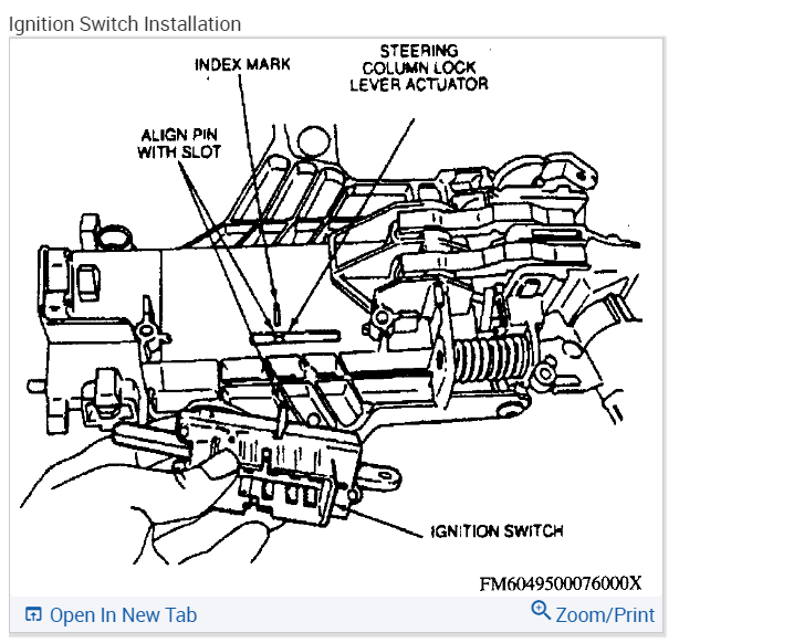
Ignition switch
147
Community 10 Create Quote
1996 Ford Truck Ranger 2WD V6-182 3.0L
Disassembly and Assembly
Vehicle Steering and Suspension Steering Column Service and Repair Procedures Steering Column Disassembly and Assembly
DISASSEMBLY AND ASSEMBLY
DISASSEMBLY
1. Remove instrument panel cover and reinforcement from vehicle.
2. Unscrew and remove the tilt wheel handle and shank.
3. Remove three screws and lower steering column shroud.
4. Remove steering column lock cylinder.
5. Remove upper steering column shroud.
6. Using door trim removal tool, remove clock spring electrical connectors from bend bracket.
7. Using door trim removal tool, disconnect two wire harness clips from steering column.
8. Remove key warning chime contact and antitheft contact from ignition lock cylinder pocket of lock cylinder housing.
9. Remove clock spring by pushing snap back at 6 o'clock position, then 3 o'clock position, then 12 o'clock position and remove from steering shaft.
10. Remove turn indicator cancel cam by pushing up with flat bladed screwdriver.
11. Remove ignition switch.
12. Remove upper bearing retainer snap ring and steering column upper bearing spring.
13. Remove steering column tube bearing sleeve and steering column upper bearing tolerance ring.
14. Remove gearshift lever.
15. Remove three screws attaching brake shift interlock solenoid and transmission shift selector position insert.
16. Remove brake shift interlock solenoid and transmission shift selector position insert together.
17. If necessary, remove push nut and separate brake shift interlock solenoid and transmission shift selector position insert.
18. Remove two screws and transmission control selector arm.
19. Remove gearshift tube bushing clamps, transmission column shift selector tube and assembled parts.
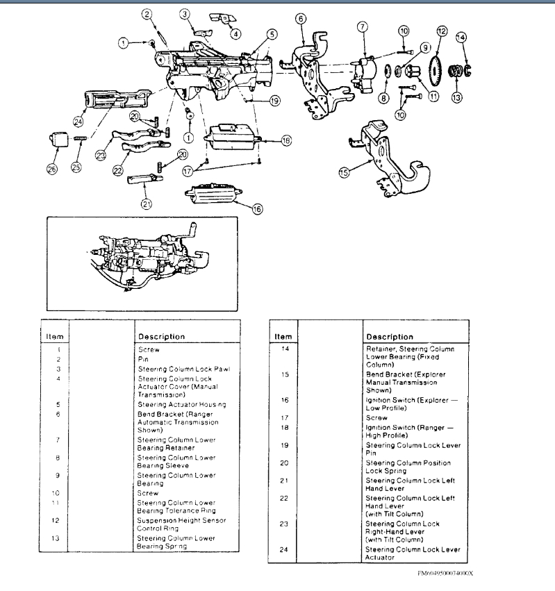
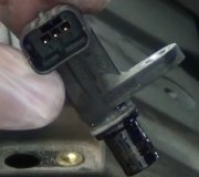
Actuator
imageOpen In New TabZoom/Print
20. Pry on one end of steering column lock lever pin which is sticking out.
21. Pull steering column lock lever pin with vise grips and remove column shift lock pawl.
22. Remove plastic bearing retainer from lock cylinder bore.
23. Remove steering column lock housing bearing from lock cylinder bore
24. Remove steering column lock gear.
25. On models with tilt column, remove steering column lower bearing spring.
26. Remove suspension height sensor control ring and lower column bearing tolerance ring.
27. On models with fixed column, remove steering column bearing retainer and steering column tolerance ring.
28. Remove steering column lower bearing retainer and steering column bend bracket.
29. Remove two pivot bolts.
WARNING: Steering column position spring will release when bolts are removed.
30. Remove lock cylinder housing.
31. Remove steering shaft from steering column.
32. Remove upper and lower steering column lock actuators.
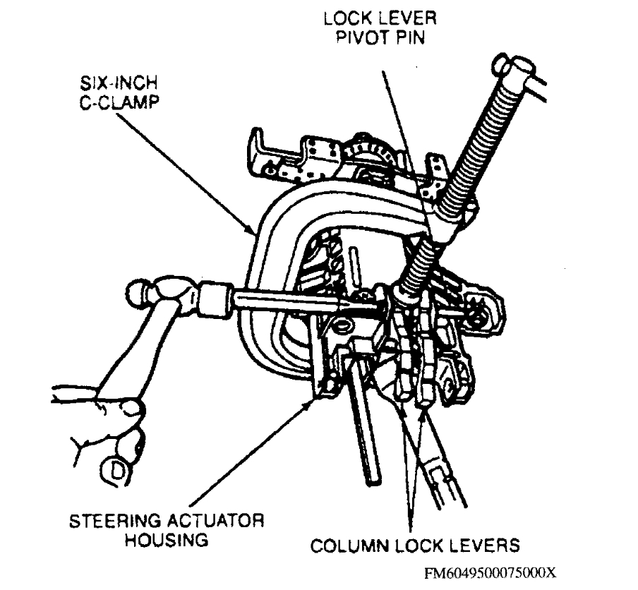
Locking Levers & Springs
33. On models with tilt column, secure locating levers with six inch C-clamp and remove steering column locking levers and springs.
ASSEMBLY
1. With actuator housing upside down, slide steering shaft into steering actuator housing.
2. Lubricate lower steering column lock lever actuator and upper steering column lock lever actuator with suitable grease.
3. Assemble lower steering column lock lever actuator and slide into place in steering actuator housing.
4. Position steering column position lock spring and left column lock lever. Using six inch C-clamp, compress steering column position lock spring while aligning pin hole in column lock lever with pin holes in steering actuator housing. Tap in lock lever pivot pin up to center pin support of steering actuator housing.
5. Insert small nut between column lock lever and steering actuator housing to hold up column lock lever. Slowly loosen and remove C-clamp.
6. Position steering column position lock spring and right column lock lever. Using six inch C-clamp, compress steering column position lock spring while aligning pin hole in column lock lever with pin holes in steering actuator housing. Tap in lock lever pivot pin up to center pin support of steering actuator housing. Align with suitable punch and leave punch in place.
7. Tap in lock lever pivot pin, driving out punch at the same time, until left end of pin is flush with pin support of steering actuator housing.
8. Position nut between right column lock lever and steering actuator housing. Slowly remove C-clamp and remove.
9. Position lock cylinder housing on steering shaft and upper steering column lock lever actuator.
10. On models with tilt column, proceed as follows:
a. Insert steering column position lock spring between lock cylinder housing and steering actuator housing.
B. Position C-clamp on outside of column position spring pads.
C. Tighten C-clamp drawing lock cylinder housing and steering actuator housing together, compressing steering column position lock spring. At the same time, use punch to align bushings in lock cylinder housing with threaded pivot bolt holes in steering actuator housing.
D. Lubricate pivot holes with suitable grease.
E. When holes and bushings are aligned, install pivot bolts and torque to 14-19 ft lb.
F. Using long, thin screwdriver, remove nuts from underneath right and left column lock levers.
G. Slowly loosen and remove C-clamp.
11. On models with fixed column, proceed as follows:
a. Position lock cylinder housing on upper steering column lever actuator and steering shaft.
B. Align bushings in lock cylinder housing with threaded pivot bolt holes in lock lever actuator housing.
C. Lubricate pivot bolt holes with suitable grease.
D. When holes and bushings are aligned, install pivot bolts and torque to 14-19 ft lb.
E. Using long, thin, screwdriver, remove nut from underneath left column lock lever.
12. Install steering column lower bearing retainer and steering column lower mounting bracket. Torque screws to 5-8 ft lb.
13. On models with tilt column, install suspension height sensor control ring, steering column upper bearing tolerance ring and steering column upper bearing spring to steering shaft.
14. On models with fixed column, install steering column upper bearing tolerance ring and steering column upper bearing retainer.
15. Position steering column lock pawl in steering actuator housing and install steering lock with suitable small hammer. Tap steering lock pawl pin until flush with steering actuator housing.
16. Install tolerance ring and sleeve over steering shaft to upper bearing.
17. Install steering column upper bearing spring and new snap ring on top side of steering column upper bearing spring using 3/4 inch (inner diameter) by 2 1/2 inch long PVC pipe.
18. Install turn indicator cancel cam with flush surface up.
19. Install ignition switch. Align pin from ignition switch with slot in lock/column assembly. Position slot in lock/column assembly with index mark on casting. Ignition switch should be in RUN position. Install steering column lock gear. Coat gear with suitable ignition lock grease.
20. Lubricate steering column lock housing bearing.
21. With actuator rack in 12 o'clock position, place bearing with tang inboard and in 5 o'clock position in lock cylinder. Insert tip of screwdriver into double-D slot of bearing, then turn counterclockwise 90°.
22. Install plastic bearing retainer.
23. Install shift control tube assembly.
24. Install transmission shift selector position insert and brake shift interlock solenoid assembly. Torque screws to 45-97 in lb.
25. Align clock spring to column shaft and mounting tabs and slide onto shaft. Push on clock spring to snap three tabs onto lock cylinder housing.
26. Install clock spring connector retainers into holes in steering column.
27. Install clock spring retainers into holes in steering column bend bracket.
28. Install key warning chime contact and antitheft contact into ignition lock cylinder pocket in lock cylinder housing. Ensure contacts do not slip out of ignition lock cylinder pocket.
29. Install upper steering column shroud.
30. Push ignition lock cylinder into place.
31. Install lower steering column shroud.
32. On models with tilt column, screw in tilt wheel handle and shank.
Check out the images (below). Please let us know what happens.
Images (Click to make bigger)
Saturday, October 29th, 2022 AT 11:25 AM