since you provided no motor, i assume the 2.3
https://www.2carpros.com/diagrams/ford/ranger/1985
An access plug is provided in the cam drive belt cover so that camshaft timing can be checked without removal of the cover or any other parts.
Remove access plug from cam drive belt cover.
Set crankshaft to TDC by aligning the TC mark on the timing belt cover with notch on crankshaft pulley.
CAUTION: Always rotate crankshaft clockwise, which is the normal direction of rotation. Reverse rotation (counterclockwise) may cause the timing belt to jump time due to the arrangement of the timing belt tensioner.
Look through the access hole in the belt cover to be sure that the timing mark on the camshaft drive sprocket is aligned with the pointer on the inner timing belt cover assembly.
Remove the distributor cap and check that the distributor rotor is facing the No. 1 position on the distributor cap.
If belt timing is satisfactory, install distributor cap and belt cover access plug. If belt timing is unsatisfactory, continue on to "Adjustment or Replacement" procedure.
Adjustment Or Replacement
Remove Thermactor pump drive belt, then the fan and water pump pulley.
Remove alternator drive belt, then drain cooling system and remove upper radiator hose.
Remove crankshaft pulley, then the thermostat housing and gasket.
On models equipped with power steering, disconnect power steering pump from bracket and position aside.
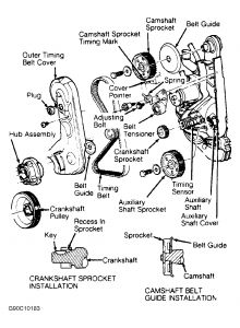
Timing belt outer cover. Exploded view
Remove timing belt outer cover attaching bolts and the cover.
Loosen belt tensioner adjustment bolt.
Using tool, T74P-6254-A positioned on tension spring roll pin, retract tensioner, then tighten adjustment screw to hold tensioner in retracted position.
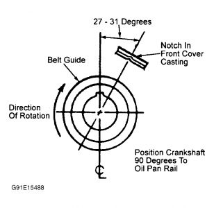
Remove crankshaft pulley and belt guide.
Remove timing belt and inspect for signs of wear and damage. Replace as necessary.
Position the camshaft and crankshaft sprocket as shown.
Remove distributor cap, then set distributor rotor to No. 1 firing position by turning the auxiliary shaft as necessary.
Install timing belt on crankshaft sprocket, then working counterclockwise, position belt on auxiliary sprocket and camshaft sprocket. Ensure timing marks do not change position.
Align belt on sprockets, then loosen tensioner adjustment bolt to allow tensioner to move against the belt.
Remove spark plugs. Failure to remove spark plugs may result in timing belt jumping time during next step.
Rotate the crankshaft two complete turns in normal rotation to remove slack from belt. Tighten tensioner adjustment and pivot bolts to specifications.
Recheck timing mark alignment, then install crankshaft pulley and belt guide.
Timing belt outer cover. Exploded view
Install timing belt cover and torque to specifications. Install spark plugs.
Start engine and set ignition timing to specifications.
Nov 11, 2020 at 6:36 PM
(Merged)