2006 Ford Mustang EEC fuse

Tiny
SHAWN41
  • MEMBER
  • 2006 FORD MUSTANG
  • V8
  • 2WD
  • AUTOMATIC
  • 175,000 MILES
My EEC fuse keeps blowing everytime I turn the key on. Also my theft light is blinking and stays blinking. The car turns over but will not start, like it is not getting gas.
Tuesday, September 30th, 2008 AT 12:02 PM

22 Replies

Tiny
MERLIN2021
  • MECHANIC
  • 17,250 POSTS
Any aftermarket electronics? Remote starter? EEC fuse will blow if the tach wire is grounding out. If any aftermarket stuff try pulling the fuses for them.
Was this
answer
helpful?
Yes
No
Tuesday, September 30th, 2008 AT 1:53 PM
Tiny
SHAWN41
  • MEMBER
  • 13 POSTS
No after market other than the old radio that was in it when I bought it.
Was this
answer
helpful?
Yes
No
Tuesday, September 30th, 2008 AT 2:25 PM
Tiny
SHAWN41
  • MEMBER
  • 13 POSTS
I unhooked the radio fuse and took out the computer and it still blew the fuse
Was this
answer
helpful?
Yes
No
-1
Tuesday, September 30th, 2008 AT 3:39 PM
Tiny
MERLIN2021
  • MECHANIC
  • 17,250 POSTS
When the EEC fuse blows, you have no spark, it stands for Electronic Engine control. If you can find the PCM and check the connections to it. Have it scanned for any codes.
Was this
answer
helpful?
Yes
No
Tuesday, September 30th, 2008 AT 5:15 PM
Tiny
SHAWN41
  • MEMBER
  • 13 POSTS
Could the aternator be causing this problem? I have been hearing the brushes rubbing when I turn the car off, also the voltage on the panel runs a little on the low side just a tad below the 12v mark.
Was this
answer
helpful?
Yes
No
Tuesday, September 30th, 2008 AT 5:46 PM
Tiny
SHAWN41
  • MEMBER
  • 13 POSTS
Is this the PCM and how do i get it checked?


https://www.2carpros.com/forum/automotive_pictures/249114_P9290014_1.jpg

Was this
answer
helpful?
Yes
No
Tuesday, September 30th, 2008 AT 6:22 PM
Tiny
SHAWN41
  • MEMBER
  • 13 POSTS
1996 mustang not 2006
Was this
answer
helpful?
Yes
No
Thursday, October 2nd, 2008 AT 10:52 AM
Tiny
MERLIN2021
  • MECHANIC
  • 17,250 POSTS
I don't know what they will charge, but yes Ford can test/ reflash them out of the car.
Was this
answer
helpful?
Yes
No
+1
Thursday, October 2nd, 2008 AT 3:33 PM
Tiny
SHAWN41
  • MEMBER
  • 13 POSTS
One last question:
I noticed today that my airbag lightflashes in a 5-2 sequence, with the key all the way turned on but not started, cause it wont start for the theft light and the eec fuse blown. Could this be connected?
Was this
answer
helpful?
Yes
No
Thursday, October 2nd, 2008 AT 5:40 PM
Tiny
MERLIN2021
  • MECHANIC
  • 17,250 POSTS
52= low battery voltage, I think you need to trace your tach wire it's the one labeled TACH on the coil, if it grounds out, the EEC fuse will blow and wont work until the short is fixed. Try removing it from the coil, install a new fuse, turn the key on and see if the fuse blows, if not, your coil could even have an internal short. The other thing to remeber, is you need at least 9 volts for the PCM to work! C harge the battery, then retest!
Was this
answer
helpful?
Yes
No
Friday, October 3rd, 2008 AT 3:05 PM
Tiny
SHAWN41
  • MEMBER
  • 13 POSTS
Thanks I will try this weekend if it works I will let you know.
Was this
answer
helpful?
Yes
No
Friday, October 3rd, 2008 AT 6:35 PM
Tiny
MERLIN2021
  • MECHANIC
  • 17,250 POSTS
OK.
Was this
answer
helpful?
Yes
No
Saturday, October 4th, 2008 AT 10:47 AM
Tiny
SHAWN41
  • MEMBER
  • 13 POSTS
Did not work, It blows the ecc fuse everytime, I tried unhooking the computor, fuse blows, unhooked the coils fuse blows what else goes thru that fuse? 96 mustang gt
Was this
answer
helpful?
Yes
No
Saturday, October 4th, 2008 AT 12:14 PM
Tiny
SHAWN41
  • MEMBER
  • 13 POSTS
Here is a pic of my engine


https://www.2carpros.com/forum/automotive_pictures/249114_PA030001_1.jpg

Was this
answer
helpful?
Yes
No
Saturday, October 4th, 2008 AT 12:30 PM
Tiny
MERLIN2021
  • MECHANIC
  • 17,250 POSTS
Time to run some circuit tests.
SYSTEM/COMPONENT TESTS - EEC-V -1996 Ford Mustang GT
Page 1 of 15
ARTICLE BEGINNING
INTRODUCTION
Before testing separate components or systems, perform basic diagnostic procedures in appropriate F - BASIC TESTING article. Since many computer-controlled and monitored components set a Diagnostic Trouble Code (DTC) if they malfunction, also perform self-diagnostics in appropriate G - TEST W/CODES article.

NOTE: Testing individual components does not isolate short or open circuits. Perform all voltage tests with a Digital Volt-Ohmmeter (DVOM) with a minimum 10-megohm input impedance, unless stated otherwise in test procedure. Use DVOM to isolate shorted or open wiring harness.
NOTE: For identification of circuits and terminals referenced in test procedures, see appropriate WIRING DIAGRAMS article.

COMPUTERIZED ENGINE CONTROLS
POWERTRAIN CONTROL MODULE

Ground Circuits
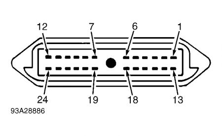
1.Using a DVOM, check for continuity to ground at the following Powertrain Control Module (PCM) connector terminals. See IDENTIFYING POWERTRAIN CONTROL MODULE PWR GND TERMINALS table. See Fig. 1 . If continuity does not exist, repair open ground circuit as necessary. If continuity exists, go to next step.
IDENTIFYING POWERTRAIN CONTROL MODULE PWR GND TERMINALS Application PCM Harness Connector Terminal No. All Others 24, 51, 76, 77 & 103 Contour & Mystique, & Escort & Tracer (1.9L) 24, 51, 77 & 103
2.Touch negative lead of DVOM to a good ground. With vehicle running, backprobe positive lead of DVOM to each ground terminal. DVOM should indicate less than one volt. If reading is greater than one volt, check for open, corrosion or loose connection on ground lead.

Power Circuits
Turn ignition off. Using a DVOM, check for battery voltage between ground and PCM terminal No. 55 (KAPWR). Turn ignition switch to START or RUN position. Check for battery voltage between ground and PCM connector terminals No. 71 and 97 (VPWR). If battery voltage is not present, power is not being supplied from EEC power relay. See CIRCUIT TEST B under CIRCUIT TESTS

10/4/2008
SYSTEM/COMPONENT TESTS - EEC-V -1996 Ford Mustang GT
Page 2 of 15
in appropriate G - TEST W/CODES article.
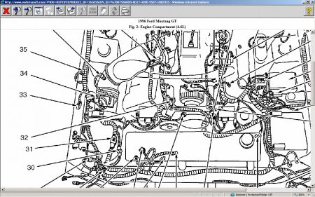
POWERTRAIN CONTROL MODULE LOCATION
Application Aerostar, Crown Victoria, Bronco, Econoline, Grand Marquis, Pickup & Town Car Continental Rear Center Of Engine Compartment Under Splash Cover Contour & Mystique Right Rear Corner Of Engine Compartment, Behind Power Steering Reservoir Cougar, Mustang & Thunderbird In Passenger Compartment, Behind Right Kick Panel Escort & Tracer In Passenger Compartment, Below Center Of Instrument Panel Explorer, Mountaineer, Ranger, Sable, Taurus & Windstar Mark VIII In Passenger Compartment, On Left Side Cowl Behind Instrument Panel Location Left Rear Corner Of Engine Compartment, Near Brake Booster In Engine Compartment, Right Rear Side On Cowl

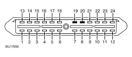
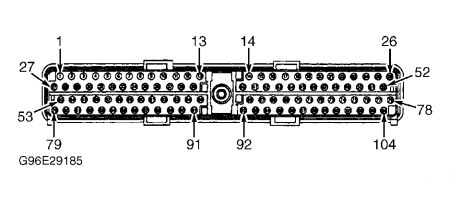
Fig. 1: Identifying Powertrain Control Module 104-Pin Connector Terminals
ENGINE SENSORS & SWITCHES

NOTE: Component tests are included when provided by manufacturer. If component tests are not provided, see appropriate test in G - TEST W/CODES article when stated. For additional sensor specifications, see appropriate K - SENSOR RANGE CHARTS article.

AIR CONDITIONING PRESSURE SWITCH

10/4/2008
SYSTEM/COMPONENT TESTS - EEC-V -1996 Ford Mustang GT
Page 3 of 15
For Air Conditioning Pressure (ACP) switch testing procedure and specifications, see CIRCUIT TEST DS under CIRCUIT TESTS in appropriate G - TEST W/CODES article.
BRAKE ON/OFF SWITCH
For Brake On/Off (BOO) switch testing procedure and specifications, see CIRCUIT TEST FD under CIRCUIT TESTS in appropriate G - TEST W/CODES article.
CAMSHAFT POSITION SENSOR (4.0L & 5.0L)
For Camshaft Positon Sensor testing procedure, see CIRCUIT TEST DR - CYLINDER IDENTIFICATION for 4.0L engine, or CIRCUIT TEST DR - CYLINDER IDENTIFICATION
for 5.0L engine.
CLUTCH PEDAL POSITION SWITCH
For Clutch Pedal Position (CPP) switch testing procedure and specifications, see CIRCUIT TEST TA under CIRCUIT TESTS in appropriate G - TEST W/CODES article.
ENGINE COOLANT TEMPERATURE SENSOR

Tips     Click a link to view tip

Tech1 coolant temperature sensor
Engine Coolant Temperature (ECT) sensor uses a 5-volt reference voltage during engine operation. To check ECT signal voltage, backprobe between signal terminal and ground with engine running. To check sensor resistance, disconnect sensor and measure resistance between sensor terminals. For specifications, see ENGINE COOLANT TEMPERATURE SENSOR SPECIFICATIONS table. For additional testing information, see CIRCUIT TEST DA under CIRCUIT TESTS in appropriate G - TEST W/CODES article.
ENGINE COOLANT TEMPERATURE SENSOR SPECIFICATIONS (1) Temperature °F ( °C) (2) Volts (3) Ohms 50 (10) 3.51 58,750 68 (20) 3.07 37,300 86 (30) 2.60 24,270 104 (40) 2.13 16,150 122 (50) 1.70 10,970 140 (60) 1.33 7700 158 (70) 1.02 5370 176 (80) 0.78 3840 194 (90) 0.60 2800

10/4/2008
SYSTEM/COMPONENT TESTS - EEC-V -1996 Ford Mustang GT
Page 4 of 15
212 (100) 230 (110) 248 (120)
0.46 0.35 0.27
2070 1550 1180
(1) Values may differ by as much as 15 percent.
(2) Backprobe between signal terminal and ground with engine running.
(3) Measure resistance between sensor terminals.

HEATED OXYGEN SENSOR
1.Faults in Heated Oxygen Sensor (HO2S) or circuit should set a Diagnostic Trouble Code (DTC). Perform QUICK TEST in appropriate G - TESTS W/CODES article. If no DTC has been set, check HO2S HTR resistance. Using a DVOM, measure resistance between HO2S HTR GND and VPWR terminals. See appropriate WIRING DIAGRAMS article. If resistance is 3-30 ohms, HO2S HTR circuit is okay, go to next step. If resistance is not 3-30 ohms, replace HO2S sensor. 2.With ignition off. Measure resistance between HO2S HTR GND terminal and HO2S case. Measure resistance between HO2S HTR GND and SIG RTN terminals. Measure resistance between HO2S VPWR terminal and HO2S case. If each resistance measurement is more than 10 k/ohms, HO2S is okay. If any resistance is 10 k/ohms or less, replace HO2S. For additional testing information, see CIRCUIT TEST H under CIRCUIT TESTS in appropriate G - TEST W/CODES article.
INERTIA FUEL SHUTOFF SWITCH
Ensure ignition is off. Locate Inertia Fuel Shutoff (IFS) switch. See INERTIA FUEL SHUTOFF SWITCH LOCATIONS table. Shake or lightly tap on IFS switch to cause switch to open and reset button should pop up. Fuel pump should not operate and car should stall. Push down on reset button. Fuel pump should operate.
INERTIA FUEL SHUTOFF SWITCH LOCATIONS Application Location Aerostar, Bronco, Econoline, Pickup & Ranger Behind Right Kick Panel Continental, Crown Victoria & Grand Marquis, Mark VIII & Town Car Contour & Mystique Behind Left Kick Panel Escort & Tracer Right Side Of Trunk Or Cargo Area, Above Wheel Well Explorer & Mountaineer Behind Instrument Panel, Below Radio Mustang Lower Left Rear Corner Of Trunk Sable & Taurus Sedan Right Side Of Trunk Behind Wheel Well Wagon Behind Right Rear Panel In Cargo Area Windstar Behind Right Rear Panel In Cargo Area On Left Side Of Trunk, Behind Trim Panel

10/4/2008
SYSTEM/COMPONENT TESTS - EEC-V -1996 Ford Mustang GT
Page 5 of 15
INTAKE AIR TEMPERATURE SENSOR
Intake Air Temperature (IAT) sensor uses a 5-volt reference voltage during engine operation. To check IAT signal voltage, backprobe between signal terminal and ground with engine running. To check sensor resistance, disconnect sensor and measure resistance between sensor terminals. For specifications, see INTAKE AIR TEMPERATURE SENSOR SPECIFICATIONS table. For additional testing information, see CIRCUIT TEST DA under CIRCUIT TESTS in appropriate G - TESTS W/CODES article.
INTAKE AIR TEMPERATURE SENSOR SPECIFICATIONS (1) Temperature °F ( °C) (2) Volts (3) Ohms 50 (10) 3.51 58,750 68 (20) 3.07 37,300 86 (30) 2.60 24,270 104 (40) 2.13 16,150 122 (50) 1.70 10,970 140 (60) 1.33 7700 158 (70) 1.02 5370 176 (80) 0.78 3840 194 (90) 0.60 2800 212 (100) 0.46 2070 230 (110) 0.35 1550 248 (120) 0.27 1180

(1) Values may differ by as much as 15 percent.
(2) Backprobe between signal terminal and ground with engine running.
(3) Measure resistance between sensor terminals.

KNOCK SENSOR
Faults in Knock Sensor (KS) or circuit should set a Diagnostic Trouble Code (DTC). See QUICK TEST in appropriate G - TESTS W/CODES article. If no DTC has been set, go to CIRCUIT TEST DG under CIRCUIT TESTS in appropriate G - TESTS W/CODES article for KS and circuit testing.
MASS AIRFLOW SENSOR
Faults in Mass Airflow (MAF) sensor or circuit should set a Diagnostic Trouble Code (DTC). See QUICK TEST in appropriate G - TESTS W/CODES article. If no DTC has been set, go to CIRCUIT TEST DC under CIRCUIT TESTS in appropriate G - TESTS W/CODES article for MAF sensor and circuit testing.
PARK/NEUTRAL POSITION SWITCH
For Park/Neutral Position (PNP) switch test procedures, see CIRCUIT TEST TA under CIRCUIT

10/4/2008
SYSTEM/COMPONENT TESTS - EEC-V -1996 Ford Mustang GT
Page 6 of 15
TESTS in appropriate G - TEST W/CODES article.
POWER STEERING PRESSURE SWITCH
For Power Steering Pressure (PSP) switch test procedures, see CIRCUIT TEST FF under CIRCUIT TESTS in appropriate G - TEST W/CODES article.
THROTTLE POSITION SENSOR
Ensure none of following conditions exist:
à   Binding throttle linkage.
à   TP sensor loose or not seated properly.
à   Throttle plate not fully closed.
Faults in TP sensor or circuit should set a Diagnostic Trouble Code (DTC). See QUICK TEST in appropriate G - TESTS W/CODES article. If no DTC has been set, see CIRCUIT TEST DH under CIRCUIT TESTS in appropriate G - TESTS W/CODES article for additional sensor and circuit testing.
TRANSMISSION RANGE SENSOR
For Transmission Range (TR) sensor test procedures, see CIRCUIT TEST TD under CIRCUIT TESTS in appropriate G - TEST W/CODES article.
VEHICLE SPEED SENSOR
Faults in Vehicle Speed Sensor (VSS) or circuit should set a Diagnostic Trouble Code (DTC). See QUICK TEST in appropriate G - TESTS W/CODES article. If no DTC has been set, go to CIRCUIT TEST DP under CIRCUIT TESTS in appropriate G - TESTS W/CODES article for VSS and circuit testing.
MODULES, MOTORS, RELAYS & SOLENOIDS
CANISTER PURGE SOLENOID
For diagnostic procedures for Canister Purge (CANP) solenoid, see CANISTER PURGE SOLENOID under FUEL EVAPORATION under EMISSION SYSTEMS & SUB-SYSTEMS.
CANISTER VENT SOLENOID
For diagnostic procedures for Canister Vent (CV) solenoid, see CANISTER VENT SOLENOID under FUEL EVAPORATION under EMISSION SYSTEMS & SUB-SYSTEMS.

10/4/2008
SYSTEM/COMPONENT TESTS - EEC-V -1996 Ford Mustang GT
Page 7 of 15
EGR VACUUM REGULATOR SOLENOID
For diagnostic procedures for EGR Vacuum Regulator (EVR) solenoid, see EGR VACUUM REGULATOR SOLENOID under EXHAUST GAS RECIRCULATION under EMISSION
SYSTEMS & SUB-SYSTEMS.
EVAP CANISTER
For diagnostic procedures for EVAP canister, see EVAP CANISTER under FUEL EVAPORATION under EMISSION SYSTEMS & SUB-SYSTEMS.
FUEL PUMP RELAY

NOTE: To identify fuel pump relay terminals, refer to numbers molded on relay. Two different numbered relays are used. Fuel pump relay terminals may be numbered 1-5 or terminals may be numbered 30, 85, 86, 87 and 87A. On relays that are numbered 1-5; terminals for relay coil are terminals No. 1 and 2. On relays that are numbered 30, 85, 86, 87 and 87A; terminals for relay coil are terminals No. 85 and 86.
1.Turn ignition off. On fuel pump relays that terminals are numbered 1-5, measure resistance between relay terminal No. 1 and all other relay terminals. Resistance should be 40-120 ohms between terminals No. 1 and 2 and more than 10 k/ohms between terminal No. 1 and other relay terminals. 2.On fuel pump relays that terminals are numbered 30, 85, 86, 87 and 87A, measure resistance between relay terminal No. 85 and all other relay terminals. Resistance should be 40-120 ohms between terminals No. 85 and 86 and more than 10 k/ohms between terminal No. 85 and other relay terminals. On both relays, if resistance is not as specified replace relay. If resistance is okay, see TEST KA under CIRCUIT TESTS in appropriate G - TESTS W/CODES article for additional fuel pump circuit testing procedures.
FUEL TANK PRESSURE SENSOR
For Fuel Tank Pressure (FTP) sensor test procedures, see CIRCUIT TEST HX under CIRCUIT TESTS in appropriate G - TEST W/CODES article.
IDLE AIR CONTROL SOLENOID
1.Idle Air Control (IAC) Solenoid is a by-pass air type. Ensure ignition is off. Disconnect IAC solenoid harness connector. Measure resistance between IAC solenoid connector terminals. Solenoid has an internal diode. Connect positive lead from DVOM to VPWR terminal and negative lead to IAC terminal. Resistance should be 6-13 ohms. If resistance is not 6-13 ohms, replace solenoid. If resistance is 6-13 ohms, go to next step. 2.Measure resistance between either IAC solenoid terminal and IAC solenoid case. If resistance is 10 k/ohms or less, replace IAC solenoid. If resistance is more than 10 k/ohms, IAC solenoid may be okay. See CIRCUIT TEST KE under CIRCUIT TESTS in appropriate G - TESTS

10/4/2008
SYSTEM/COMPONENT TESTS - EEC-V -1996 Ford Mustang GT
Page 8 of 15
W/CODES article for additional testing and specifications.
PURGE FLOW SENSOR
For diagnostic procedures for Purge Flow (PF) sensor, see PURGE FLOW SENSOR under FUEL EVAPORATION under EMISSION SYSTEMS & SUB-SYSTEMS.
VAPOR MANAGEMENT VALVE
For diagnostic procedures for Vapor Management Valve (VMV), see VAPOR MANAGEMENT VALVE under FUEL EVAPORATION under EMISSION SYSTEMS & SUB-SYSTEMS.
FUEL SYSTEM
FUEL SYSTEM PRESSURE RELEASE

With Fuel Pressure Gauge

WARNING: Always relieve fuel pressure before disconnecting any fuel injection-related component. DO NOT allow fuel to contact engine or electrical components.
1.Remove fuel cap to release fuel tank pressure. Remove relief valve cap. Relief valve is located on fuel supply manifold. Using Fuel Pressure Gauge (T80L-9974-B), release fuel pressure from relief valve (Schrader valve). 2.If fuel pressure gauge is not available, disconnect electrical connector to IFS switch. For IFS switch location, see INERTIA FUEL SHUTOFF SWITCH LOCATIONS table. Crank engine for 15 seconds to reduce system pressure. Turn ignition off. Reconnect IFS switch connector.
Without Fuel Pressure Gauge
If fuel pressure gauge is not available, disconnect Inertia Fuel Shutoff (IFS) switch. For IFS location, see INERTIA FUEL SHUTOFF SWITCH LOCATIONS table under ENGINE SENSORS & SWITCHES. Remove fuel cap to release fuel tank pressure. Crank engine for 15 seconds to release system pressure.
FUEL DELIVERY

NOTE: For 1995 fuel pressure specifications, see FUEL PRESSURE SPECIFICATIONS article. For 1996 fuel pressure specifications, see FUEL PRESSURE SPECIFICATIONS article.

Fuel Pump Relay

10/4/2008
SYSTEM/COMPONENT TESTS - EEC-V -1996 Ford Mustang GT
Page 9 of 15
See FUEL PUMP RELAY under MODULES, MOTORS, RELAYS & SOLENOIDS.
CAUTION:Inspect fuel system for leaks and damage before testing fuel pump.
1) System Integrity Check

Perform the following checks:
à   Visually inspect fuel system (fuel lines, filter, pump, injectors, pressure regulator, etc.).
à   Ensure Inertia Fuel Shutoff (IFS) switch reset button is not in upper (tripped) position.
à   Ensure battery is fully charged and fuel-related fuses are okay.
à   Check fuel tank contents and fuel gauge accuracy. On vehicles with 2 fuel tanks, check both tanks. If any fault is detected, repair as necessary. If system checks are okay, go to next step.
2) Check Fuel Pressure
Install fuel pressure gauge. Check and record fuel pressure. For 1995 fuel pressure specifications, see FUEL PRESSURE SPECIFICATIONS article. For 1996 fuel pressure specifications, see FUEL PRESSURE SPECIFICATIONS article. If fuel pressure is as specified, testing is complete. If fuel pressure is not as specified, proceed as follows:
à   For Natural Gas Vehicles

Go to CIRCUIT TEST HB, step 1) under CIRCUIT TESTS in appropriate G - TEST W/CODES article.
à   For Models Except Natural Gas Vehicles

Go to CIRCUIT TEST HC, step 1) under CIRCUIT TESTS in appropriate G - TEST W/CODES article.
FUEL PRESSURE REGULATOR
See CIRCUIT TEST HC under CIRCUIT TESTS in appropriate G - TEST W/CODES article.
FUEL CONTROL

Fuel Injector Resistance
Disconnect injector harness connectors. Using DVOM, measure resistance between injector terminals. See FUEL INJECTOR RESISTANCE table. Replace any injector not within specification.

Fuel Injector Check

10/4/2008
SYSTEM/COMPONENT TESTS - EEC-V -1996 Ford Mustang GT
Page 10 of 15
Start engine and allow to idle. If engine will not start, crank engine for 10 seconds. Using a stethoscope, listen for clicking sound at each injector. If clicking sound is heard, fuel injector is operating. If clicking sound is not heard, go to CIRCUIT TEST HD, step 8) under CIRCUIT TESTS in appropriate G - TEST W/CODES article.
FUEL INJECTOR RESISTANCE (1)

Application Gasoline Models Natural Gas Models
Ohms 11-18 4-6
(1) Resistance values are for a single injector.

IDLE CONTROL SYSTEM
IDLE AIR CONTROL SOLENOID
Turn ignition off. Disconnect Idle Air Control I(AC) solenoid wiring harness connector. Connect DVOM positive lead to VPWR terminal of IAC solenoid wiring harness connector. See appropriate WIRING DIAGRAMS article. Connect DVOM negative lead to IAC terminal. If resistance is 6-13 ohms, go to next step. If resistance is not 6-13 ohms, replace IAC valve assembly.
IGNITION SYSTEM

NOTE: 1996 Taurus SHO 3.4L models use Coil On Plug (COP). COP faults should set a Diagnostic Trouble Code (DTC). For additional COP testing, see CIRCUIT TEST JF under CIRCUIT TESTS in appropriate G - TEST W/CODES article. For additional information and descriptions, see IGNITION SYSTEMS in appropriate E - THEORY & OPERATION article.

SYSTEM CHECKS
Preliminary Check
Perform following preliminary checks:
à   Visually inspect engine compartment to verify vacuum hoses and spark plug wires are properly routed and securely connected.
à   Examine all wiring harnesses and connectors for damage.
à   Ensure all ground connections are clean and tight.
à   Ensure battery is fully charged.
à   All accessories should be off during diagnosis.
Test Equipment

10/4/2008
SYSTEM/COMPONENT TESTS - EEC-V -1996 Ford Mustang GT
Page 11 of 15
Following test equipment should be used:
à   Spark Tester (D81P-6666-A Or D89P-6666-A)
à   Digital Volt-Ohmmeter (DVOM)
à   12-Volt Test Light
à   Remote Starter Switch
à   Hand Held Scan Tool
à   EEC-V Breakout Box (014-00950)
Diagnostic Aids
Test procedures are intended to identify faulty components or wiring while fault is present. If complaint is an intermittent condition, refer to H - TESTS W/O CODES article or perform CIRCUIT TEST Z under CIRCUIT TESTS in appropriate G - TEST W/CODES article.
1. Check For Diagnostic Trouble Codes (DTC)

Perform QUICK TEST in appropriate G - TEST W/CODES article. If DTCs are present, service DTCs. See appropriate CIRCUIT TEST under CIRCUIT TESTS in appropriate G - TEST W/CODES article. If DTCs are not present, go to next step.
2. Check Battery
Turn ignition on. Check battery voltage. If battery voltage is less than 12 volts, service battery as necessary and check charging system. If battery voltage is more than 12 volts, go to next step.
3. Check For Spark

Using Spark Tester (D81P-6666-A or D89P-6666-A), check for spark at each spark plug wire or coil while cranking. If spark is consistent at all spark plug wires, go to next step. If spark is not consistent, go to CIRCUIT TEST JD under CIRCUIT TESTS in appropriate G - TEST W/CODES article to test crankshaft position sensor.
4. Check Spark Plugs
Remove and inspect spark plugs. Replace plugs as necessary. If spark plugs are okay, testing is complete. If fault is still present, go to CIRCUIT TEST H under CIRCUIT TESTS in appropriate G - TEST W/CODES article. If vehicle has a no-start condition, go to CIRCUIT TEST A under CIRCUIT TESTS in appropriate G - TEST W/CODES article.
EMISSION SYSTEMS & SUB-SYSTEMS
EXHAUST CATALYST

NOTE: Perform CIRCUIT TEST HF under CIRCUIT TESTS in appropriate G - TEST W/CODES article.

10/4/2008
SYSTEM/COMPONENT TESTS - EEC-V -1996 Ford Mustang GT
Page 12 of 15

NOTE: On models equipped with Electronic Air Injection System (EAIR), go to CIRCUIT TEST HM, step 1) under CIRCUIT TESTS in appropriate G - TEST W/CODES article. On models equipped with mechanical secondary air injection system, go to CIRCUIT TEST HM, step 40) under CIRCUIT TESTS in appropriate G - TEST W/CODES article.

SECONDARY AIR INJECTION
EXHAUST GAS RECIRCULATION
EGR Valve
1.Ensure all vacuum hoses are correctly routed and securely attached. Replace any crimped or broken hoses. Ensure there is less than one in. Hg vacuum to EGR valve at idle with engine at normal operating temperature. 2.Install tachometer. Disconnect Idle Air Control (IAC) wiring harness connector. Remove and plug vacuum hose at EGR valve. Start engine and allow to idle in Neutral. Note idle speed. Using hand vacuum pump, slowly apply 5-10 in. Hg vacuum to EGR valve. When vacuum is fully applied, engine should do one or more of the following:
à   Engine should stall.
à   Idle speed should drop more than 100 RPM.
à   Idle speed should return to normal when vacuum is released.
Service or replace EGR valve if engine does not stall or idle speed does not respond as specified. Reconnect IAC harness connector. Unplug and reconnect vacuum hose at EGR valve.

EGR Vacuum Regulator Solenoid
Turn ignition off. Disconnect EGR Vacuum Regulator (EVR) solenoid wiring harness connector. Measure resistance across EVR solenoid terminals. If resistance is not 26-40 ohms, replace EVR solenoid. For additional testing, go to CIRCUIT TEST HE under CIRCUIT TESTS in appropriate G - TEST W/CODES article.
FUEL EVAPORATION

Canister Purge Solenoid
Turn ignition off. Disconnect Canister Purge (CANP) solenoid wiring harness connector. Measure resistance between CANP solenoid terminals. If resistance is not 30-90 ohms, replace CANP solenoid. For additional testing, go to CIRCUIT TEST HW under CIRCUIT TESTS in appropriate G - TEST W/CODES article.

Canister Vent Solenoid

10/4/2008
SYSTEM/COMPONENT TESTS - EEC-V -1996 Ford Mustang GT
Page 13 of 15
Turn ignition off. Disconnect CV solenoid wiring harness connector. Measure resistance between CV solenoid terminals. If resistance is not 48-65 ohms, replace CV solenoid and repeat QUICK TEST. If resistance is 45-65 ohms, solenoid is okay. If fault is still present, go to CIRCUIT TEST HX in SELF-DIAGNOSTICS - EEC-V article.
EVAP Canister
There are no moving parts in canister. Check for loose, missing, cracked or broken connections and parts. Repair or replace as necessary. There should be no liquid in canister.

Purge Flow Sensor
Turn ignition off. Disconnect Purge Flow (PF) sensor wiring harness connector. Allow sensor to cool to room temperature. Measure resistance between PFS SIG terminal and PWR GND terminal. See Fig. 2 . If resistance is less than 25.5 ohms, replace PF sensor. If resistance is 25.5 ohms or more, measure resistance between PFS SIG terminal and VPWR terminal. If resistance is not 25.65-28.35 ohms, replace PF sensor. If resistance is 25.65-28.35 ohms, measure resistance between PWR GND terminal and VPWR terminal. If resistance is more than 130 ohms, replace PF sensor. If resistance is 130 ohms or less, PF sensor is okay. If fault is still present, go to CIRCUIT TEST HW under CIRCUIT TESTS in appropriate G - TEST W/CODES article.

10/4/2008
SYSTEM/COMPONENT TESTS - EEC-V -1996 Ford Mustang GT
Page 14 of 15

Fig. 2: Identifying Purge Flow Sensor Connector Terminals

Canister Purge Valve/Vapor Management Valve
Turn ignition off. Disconnect Canister Purge Valve (CVP)/Vapor Management Valve (VMV) wiring harness connector. Using DVOM, measure resistance between CVP/VMV SIG and VPWR terminals. If resistance is not 30-36 ohms, replace CVP/VMV. If resistance is 30-36 ohms, sensor is okay. If fault is still present, go to CIRCUIT TEST HX under CIRCUIT TESTS in appropriate G - TEST W/CODES article.
POSITIVE CRANKCASE VENTILATION
1. Check Positive Crankcase Ventilation (PCV) Valve
Remove PCV valve. Shake valve and listen for rattle. If PCV valve rattles when shaken, go to

10/4/2008
SYSTEM/COMPONENT TESTS - EEC-V -1996 Ford Mustang GT
Page 15 of 15
next step. Replace PCV valve if it does not rattle when shaken.
2. Check PCV System
Start engine and warm to normal operating temperature. Disconnect hose from remote air cleaner or outlet tube. Place a stiff piece of paper over end of hose. If vacuum from hose does not hold paper in place for one minute, repair clogged or leaking hose as necessary. If vacuum from hose holds paper in place for one minute, PCV system is okay and testing is complete.

10/4/2008


https://www.2carpros.com/forum/automotive_pictures/62217_mustang_1.jpg

Was this
answer
helpful?
Yes
No
Saturday, October 4th, 2008 AT 1:26 PM
Tiny
MERLIN2021
  • MECHANIC
  • 17,250 POSTS
ENGINE COOLING FAN -1996 Ford Mustang GT
Page 1 of 6
CONSTANT CONTROL RELAY MODULE (CCRM)

Diagnostic Aids
CCRM interfaces with the EEC-V system to provide control for fuel pump, cooling fan and A/C compressor clutch. CCRM also contains EEC-V power relay, which provides battery power (VPWR) to the Powertrain Control Module (PCM) and EEC-V system. Perform this test only when instructed by QUICK TEST or if directed by a circuit test. This test is only intended to diagnose the following:
à   CCRM including EEC power relay, Fan Control/Low Fan Control (FC/LFC) relay.
à   High Fan Control (HFC) relay.
à   Harness Circuits (B +, FC, LFC, HFC, ACCS, VPWR (to CCRM), Power-To-A/C Clutch and Power-To-Low/High Speed Fan).
à   Powertrain Control Module (PCM).
To prevent replacing good components, be aware the following non-EEC related components or systems may be at fault:
à   A/C system.
à   Starting and charging system.

NOTE: For CCRM circuit identification, see appropriate wiring diagram in WIRING DIAGRAMS . For CCRM connector terminal identification,
see Fig. 1 .
Fig. 1: CCRM Connector Terminal ID (Wiring Harness Side Shown)
Courtesy of FORD MOTOR CO.
NOTE: A break in step numbering sequence occurs at this point. Procedure starts at step 15). No test procedures have been omitted.
à  Â
15) KOEO/KOER Code P1479: Check High Fan Control (HFC) Relay

Code P1479 indicates HFC primary circuit failure. Possible causes for this fault are:
à   Open or shorted HFC circuit.
à   Faulty CCRM.
à   Faulty PCM.
à   Faulty circuit.
NOTE: On Mustang 3.8L, disregard Code P1479.
Turn ignition off. Disconnect CCRM wiring harness connector. Check resistance between terminals No. 17 and 24 at CCRM wiring harness connector. If resistance is 30-100 ohms, go to step 17). If resistance is not 30-100 ohms, replace CCRM and repeat QUICK TEST.

10/4/2008
ENGINE COOLING FAN -1996 Ford Mustang GT
Page 2 of 6
17) Check HFC Circuit Continuity

Turn ignition off. Disconnect CCRM and PCM wiring harness connector. Inspect wiring, and repair if damaged. Install breakout box, leaving PCM disconnected. Check resistance between CCRM terminal No. 17 and breakout box test pin No. 46. If resistance is less than 5 ohms, go to next step. If resistance is 5 ohms or greater, repair open in HFC circuit. Remove breakout box, and repeat QUICK TEST.
18) Check HFC Circuit For Short To Power
Leave CCRM and PCM disconnected. Turn ignition on. Check voltage between negative battery terminal and breakout box test pin No. 46. If voltage is less than one volt, turn ignition off and go to next step. If voltage is one volt or greater, repair short to power and repeat QUICK TEST.
19) Check HFC Circuit For Short To Ground

Turn ignition off. Leave CCRM and PCM disconnected. Disconnect NGS scan tool from DLC. Check resistance between breakout box test pin No. 46 and test pins No. 51, 103 and 91. If all resistances are greater than 10,000 ohms, replace PCM. Remove breakout box, and repeat QUICK TEST. If any resistance is 10,000 ohms or less, repair short to ground in HFC circuit. Remove breakout box, and repeat QUICK TEST.
20) KOEO/KOER Code P1474: Check Fan Operation

Code P1474 indicates primary circuit failure in Low Fan Control (LFC) circuit or Fan Control (FC) circuit for single cooling fan systems. Possible causes for this fault are:
à   Open or shorted FC/LFC circuit.
à   Faulty CCRM.
à   Faulty PCM.
Turn ignition on. If cooling fan runs continuously, go to step 24). If cooling fan does not run continuously, go to step 22).
22) Check FC/LFC Circuit For Short To Ground
Turn ignition off. Disconnect CCRM wiring harness connector. Disconnect NGS scan tool from DLC. Disconnect PCM wiring harness connector. Inspect wiring, and repair if damaged. Install breakout box, leaving PCM disconnected. Check resistance between breakout box FC or LFC test pin and test pins No. 51, 91 and 103. See FC/LFC TEST PIN IDENTIFICATION table. If each reading is greater than 10,000 ohms, go to next step. If any reading is less than 10,000 ohms, locate and repair short to ground in FC or LFC circuit. Reconnect all components and repeat QUICK TEST.
FC/LFC TEST PIN IDENTIFICATION
Application Circuit Mustang 3.8L FC
Breakout Box Test Pin No. 45
23) Check Fan Operation

10/4/2008
ENGINE COOLING FAN -1996 Ford Mustang GT
Page 3 of 6

Turn ignition off. Connect CCRM. Leave PCM disconnected. Turn ignition on. If cooling fan runs continuously, replace PCM and repeat QUICK TEST. If cooling fan does not run continuously, replace CCRM and repeat QUICK TEST.
24) Check FC/LFC Circuit Continuity

Turn ignition off. Disconnect CCRM wiring harness connector. Disconnect PCM wiring harness connector. Inspect wiring, and repair if damaged. Install breakout box, leaving PCM disconnected. Check resistance between breakout box FC or LFC test pin and CCRM terminal No. 14. See FC/LFC TEST PIN IDENTIFICATION table. If resistance is less than 5 ohms, go to next step. If resistance is 5 ohms or greater, locate and repair open in FC or LFC circuit. Reconnect all components and repeat QUICK TEST.
25) Check FC/LFC Circuit Short To Power

Turn ignition on. Check voltage between breakout box FC or LFC test pin and negative battery terminal. See FC/LFC TEST PIN IDENTIFICATION table. If voltage is less than one volt, go to next step. If voltage is one volt or greater, locate and repair short to power in FC or LFC circuit. Reconnect all components and repeat QUICK TEST.
26) FC/LFC Circuit Fault Isolation Check

Turn ignition on. Connect a jumper wire between breakout box FC or LFC test pin and test pin No. 77. See FC/LFC TEST PIN IDENTIFICATION table. If cooling fan runs continuously, replace CCRM and repeat QUICK TEST. If cooling fan does not run continuously, replace PCM and repeat QUICK TEST.
NOTE: A break in step numbering sequence occurs at this point. Procedure skips from step 26) to step 30). No test procedures have been omitted.
30) Continuous Memory Code P1474: Check FC/LFC Circuit For Open Circuit Or Short To Power

A Continuous Memory Code P1474 indicates that circuit failure has occurred on Fan Control (FC) circuit. If Code P1474 is present, turn ignition off. Disconnect cooling fan wiring harness connector. Inspect wiring, and repair if damaged. Connect a non-powered test light between cooling fan wiring harness power circuit and ground. Turn ignition on. Test light should be off. Check for indication of fault (test light blinks or comes on) while performing one of the following:
à   Shake and bend FC/LFC circuits between CCRM and PCM.
à   Lightly tap CCRM to simulate road shock.
Turn ignition off. If fault is indicated, isolate and repair as necessary. Repeat QUICK TEST. If fault is not indicated, go to next step.
31) Check LFC/FC Circuit For Short To Ground

Leave cooling fan wiring harness connector disconnected. Leave NGS scan tool and test light

10/4/2008
ENGINE COOLING FAN -1996 Ford Mustang GT
Page 4 of 6
connected. Turn ignition on. Access Output Test Mode on NGS scan tool. Command low speed fan on. Test light should be on. Check for indication of fault (test light blinks or goes off) while performing one of following:
à   Shake and bend FC/LFC circuits between CCRM and PCM.
à   Lightly tap CCRM to simulate road shock.
Turn ignition off. If fault is indicated, isolate and repair as necessary. Repeat QUICK TEST. If fault is not indicated, problem is intermittent and cannot be duplicated at this time.
NOTE: A break in step numbering sequence occurs at this point. Procedure skips from step 31) to step 35). No test procedures have been omitted.
NOTE: On Mustang 3.8L, disregard Code P1479.
35) Continuous Memory Code P1479

A Continuous Memory Code P1479 indicates that High Fan Control (HFC) circuit failure has occurred. Turn ignition off. Leave NGS scan tool connected to DLC. Disconnect cooling fan wiring harness connector. Inspect wiring, and repair if damaged. Connect a non-powered test light between ground and Power-To-High Speed Fan circuit at cooling fan wiring harness connector. Turn ignition on. Access Output Test Mode on NGS scan tool. Command high speed fan on. Test light should be on. Check for indication of fault (test light blinks or goes off) while performing one of the following:
à   Shake and bend HFC circuit between CCRM and PCM.
à   Lightly tap CCRM to simulate road shock.
Turn ignition off. If fault is indicated, isolate and repair as necessary. Repeat QUICK TEST. If fault is not indicated, go to next step.
36) Check HFC Circuit For Short To Ground

Leave cooling fan wiring harness connector disconnected. Leave NGS scan tool and test light connected. Turn ignition on. Command high speed fan off. Test light should be off. Check for indication of fault (test light blinks or comes on) while performing the following:
à   Shake and bend HFC circuit between CCRM and PCM.
à   Lightly tap CCRM to simulate road shock.
Turn ignition off. If fault is indicated, isolate and repair as necessary. Repeat QUICK TEST. If fault is not indicated, problem is intermittent and cannot be duplicated or identified at this time.
NOTE: A break in step numbering sequence occurs at this point. Procedure skips from step 36) to step 40). No test procedures have been omitted.
40) Check Cooling Fan Operation
On Mustang models, go to next step.

10/4/2008
ENGINE COOLING FAN -1996 Ford Mustang GT
Page 5 of 6
41) Cooling Fan Does Not Operate At Any Speed

Turn ignition on. Disconnect cooling fan motor. Command fan on high speed. Check voltage between negative battery terminal and Power-To-(High Speed) Fan circuit terminal at cooling fan wiring harness connector. If voltage is 10 volts or less, go to next step. If voltage is greater than 10 volts, go to step 45).
42) Check B + Circuit To Fan Relays
Turn ignition off. Ensure cooling fan is disconnected. Disconnect CCRM. Perform appropriate test:
à   Check voltage between ground and terminals No. 3 and 4 at CCRM wiring harness connector.
Check voltage between ground and terminals No. 1, 2, 6, 7, 12 and 24 at CCRM wiring harness connector. On all models, if each reading is greater than 10 volts, go to next step. If any reading is 10 volts or less, fault exists in B + circuit. Check cooling fan related fuse/fuse links. If fuse/fuse link is blown, check for short to ground in B + circuit. Repair as necessary. If fuse/fuse link is okay, check for open B + circuit. Repair as necessary. After repair is completed, perform appropriate procedure:
à   Reconnect all components and recheck system operation.
43) Check Power To Fan(s) Circuit

Turn ignition off. Ensure CCRM and cooling fan is disconnected. Perform appropriate procedure:
à   4.6L
Check resistance of Power-To-High fan circuit (Orange/Light Blue wire) between cooling fan wiring harness connector and terminal No. 6 at CCRM wiring harness connector. Also, check resistance of Power-To-Low fan circuit (Red/Orange wire) between cooling fan wiring harness connector and terminal No. 2 of CCRM.
à   3.8L

Check resistance of Power-To-Fan circuit (Red/Orange wire) between cooling fan wiring harness connector and terminal No. 2 at CCRM wiring harness connector.
On all models, if each reading is less than 5 ohms, replace CCRM. Reconnect all components and recheck system operation. If any reading is 5 ohms or greater, locate and repair open circuit(s) between cooling fan motor and CCRM. After repair is completed, perform appropriate procedure:
à   Reconnect all components and recheck system operation.
NOTE: A break in step numbering sequence occurs at this point. Procedure skips from step 43) to step 45). No test procedures have been omitted.

10/4/2008
ENGINE COOLING FAN -1996 Ford Mustang GT
Page 6 of 6
45) Check Cooling Fan Ground Circuit

Turn ignition off. Ensure cooling fan is disconnected. Disconnect NGS scan tool from Data Link Connector (DLC). Check resistance between negative battery terminal and ground circuit terminal at cooling fan wiring harness connector. If resistance is 5 ohms or greater, locate and repair open ground circuit. Reconnect all components and recheck system operation. If resistance is less than 5 ohms, replace cooling fan motor.

10/4/2008
https://www.2carpros.com/forum/automotive_pictures/62217_ccrm_1.jpg" alt=" https://www.2carpros.com/forum/automotive_pictures/62217_ccrm_1.jpg" />
You may have to pull the fuse box, and trace the wires, test with ohm meter...


https://www.2carpros.com/forum/automotive_pictures/62217_ccrm_2.jpg

Was this
answer
helpful?
Yes
No
-1
Saturday, October 4th, 2008 AT 1:36 PM
Tiny
SHAWN41
  • MEMBER
  • 13 POSTS
None of the links above work
Was this
answer
helpful?
Yes
No
Saturday, October 4th, 2008 AT 5:38 PM
Tiny
MERLIN2021
  • MECHANIC
  • 17,250 POSTS
They arent meant to! All the testing info is in the posts! Your problem is a simple as tracing the wires out of the fuse box, or CCRM.
Was this
answer
helpful?
Yes
No
Saturday, October 4th, 2008 AT 6:10 PM
Tiny
SHAWN41
  • MEMBER
  • 13 POSTS
I traced wires back from the fuse and inserted fuses and disconnected components. The second try I disconnected the air conditioner compressor and the fuse did not blow and the car started right up. The air bag light does not blink but it is staying on.
Was this
answer
helpful?
Yes
No
+1
Thursday, October 9th, 2008 AT 3:49 PM
Tiny
MERLIN2021
  • MECHANIC
  • 17,250 POSTS
CCRM may need to be changed, unless you find a short between the A/C compressor and CCRM.
A/C-HEATER SYSTEM - MANUAL -1996 Ford Mustang GT
Page 1 of 7
TROUBLE SHOOTING
A/C INOPERATIVE OR IMPROPER OPERATION
1. A/C Clutch Operation
Start engine. Set function control to MAX A/C. Ensure battery voltage is 12.5 volts or more. Set blower switch in HI position. If A/C clutch engages, circuit is functioning properly. If A/C clutch does not engage, go to next step.
2. A/C Cycling Switch
Disconnect connector from cycling switch. Jumper wiring harness connector pins. If A/C clutch engages, go to next step. If A/C clutch does not engage, go to step 4).
3. A/C System Pressure

Turn engine off. Connect manifold gauge set. If pressure is greater than 50 psi (3.5 kg/cm 2 ), replace A/C cycling switch and go to step 1). If pressure is 50 psi (3.5 kg/cm2 ) or less, check system for leaks or low charge. Service and charge system as necessary, then go to step 1).
4. Supply Voltage At A/C Cycling Switch

Turn engine off and leave ignition switch in RUN position. Set function control to MAX A/C. Check for battery voltage at A/C cycling switch harness connector between MD5Purple wire and ground. If battery voltage is present, go to next step. If battery voltage is not present, go to step 15).
5. Supply Voltage At A/C Pressure Cut-Off Switch

Check for battery voltage at A/C pressure cut-off switch harness connector between Dark Blue /Yellow wire and ground. If battery voltage is present, go to next step. If battery voltage is not present, repair open in Dark Blue /Yellow wire and retest system.
6. A/C Pressure Cut-Off Switch

Check continuity between A/C pressure cut-off switch harness connector Dark Blue /Yellow wire and MD2Dark Green/Orange wire. If continuity is present, go to next step. If continuity is not present, replace A/C pressure cut-off switch.
7. Supply Voltage At Constant Control Relay Module (CCRM)
Check for battery voltage at CCRM harness connector between pin No. 21 (Dark Green /Orange wire) and ground. See Fig. 2 . If battery voltage is present, go to next step. If battery voltage is not present, repair open in Dark Green /Orange wire between CCRM and A/C pressure cut-off switch.
8. PCM Supply Voltage From A/C Pressure Cut-Off Switch

10/9/2008
A/C-HEATER SYSTEM - MANUAL -1996 Ford Mustang GT
Page 2 of 7
Check for battery voltage at Dark Green /Orange wire of PCM connector pin No. 41. See Fig. 3 . If battery voltage exists, go to next step. If battery voltage does not exist, repair open in Dark Green /Orange wire and retest system.
9. CCRM Output To PCM

Disconnect CCRM pin No. 22 (Pink /Yellow wire) from connector. If A/C clutch does not engage, go to next step. If A/C clutch engages, repair WOT cut-out switch and ECT sensor. See TESTS W/CODES article in the ENGINE PERFORMANCE section.
10. CCRM Clutch Output
Using a test light, probe at CCRM connector pin No. 23 (Black /Yellow wire). See Fig. 2 . If test light does not come on, replace CCRM. If test light comes on, go to next step.
Fig. 2: Constant Control Relay Module (CCRM) Connector Pins I.D.
Courtesy of FORD MOTOR CO.
Fig. 3: Identifying PCM Connector Pins
Courtesy of FORD MOTOR CO.
11. Supply Voltage To A/C Clutch

Disconnect A/C clutch connector. Using a test light, probe Black /Yellow wire at A/C clutch connector. If test light does not come on, repair open in Black /Yellow wire. Retest system. If test light comes on, go to next step.
12. A/C Clutch Ground Circuit

Using an ohmmeter, check resistance between A/C clutch connector Black wire and ground. If resistance is one ohm or less, go to next step. If resistance is greater than one ohm, repair open in Black wire and retest system. If ground still does not exist, replace CCRM and retest system.
13. A/C Clutch Coil Resistance
Using an ohmmeter, check resistance between A/C clutch connector terminals. If resistance is greater than 6 ohms, replace A/C clutch coil. If resistance is 6 ohms or less, go to next step.
14. A/C Clutch Coil Current Draw
Using an ammeter, check current draw of A/C clutch coil. If current draw is 2.5-4.5 amps, adjust A/C clutch gap and retest system. If current draw is not 2.5-4.5 amps, replace A/C clutch coil.
15. Supply Voltage At A/C Function Control Switch

Using a test light, probe White/MD5Purple wire of A/C function control switch. If test light does not come on, go to next step. If test light comes on, go to step 18).
16. Supply Voltage To A/C Function Control Switch

10/9/2008
A/C-HEATER SYSTEM - MANUAL -1996 Ford Mustang GT
Page 3 of 7
Check for battery voltage at output side of fuse No. 6 (15-amp). If battery voltage does not exist, go to next step. If battery voltage exists, repair open White/MD11Light Blue wire between fuse No. 6 and A/C function control switch. Retest system.
17. White/Purple Wire

Connect an ohmmeter between output side of fuse No. 6 and ground. Disconnect A/C function control switch connector. If resistance is greater than 5 ohms, go to next step. If resistance is 5 ohms or less, repair short to ground in White /Purple wire. Replace fuse and retest system.
18. A/C Function Control Switch MAX A/C Position
Reconnect the A/C function control switch connector. Check for battery voltage at Purple wire of A/C function control switch connector. If battery voltage exists, go to next step. If battery voltage does not exist, replace A/C function control switch and retest system.
19. A/C Function Control Switch A/C Position
Place A/C function control switch in A/C position. Check for battery voltage at MD5Purple wire of A/C function control switch connector. If battery voltage exists, go to step 5). If battery voltage does not exist, replace A/C function control switch and retest system.
BLOWER MOTOR INOPERATIVE
1. Blower Motor Operation

Turn ignition on. Place A/C function control switch in FLOOR position. Place blower motor switch in HI position. If blower motor operates, go to next step. If blower motor does not operate, go to step 4).
2. Blower Motor LO Speed

Rotate blower motor switch to LO position. If blower motor operates, wiggle wires and check for intermittent connection. Repair if necessary. If blower motor does not operate, go to next step.
3. Blower Motor Resistor

Check blower motor resistor coils and thermal limiter for continuity. If blower motor resistor has continuity, repair open in Orange /Black wire from blower motor to blower motor switch or Black wire from blower motor resistor to ground. If blower motor resistor does not have continuity, replace blower motor resistor and retest system.
4. Blower Motor

Turn ignition off. Ground Orange /Black wire at blower motor. Turn ignition on, long enough to check blower motor operation. If blower motor operates, repair open Orange /Black wire between blower motor splice before blower motor switch and blower motor resistor. If blower motor does not operate, check blower motor fuse. If fuse is okay, go to next step. If fuse is blown, go to step 8).

10/9/2008
A/C-HEATER SYSTEM - MANUAL -1996 Ford Mustang GT
Page 4 of 7
5. Function Control Switch

Remove A/C control panel from instrument panel to gain access to electrical connectors. Check for battery voltage at Dark Blue /Light Green wire. If battery voltage does not exist, go to next step. If battery voltage exists, go to step 7).
6. Supply Voltage

Check for battery voltage at Brown /Orange wire of A/C function control switch. If battery voltage does not exist, repair open in MD6Brown/Orange wire between fuse panel and A/C function control switch. If battery voltage exists, test A/C function control switch for continuity in all positions except OFF. If continuity does not exist, replace A/C function control switch.
7. Voltage

Reinstall A/C control panel. Check for battery voltage at Dark Blue /Light Green wire of blower motor. If battery voltage exists, replace blower motor. If battery voltage does not exist, repair open in Dark Blue /Light Green wire between blower motor and A/C control panel.
8. Circuit

Turn ignition off. Disconnect blower motor harness connector and install new fuse. Turn ignition on. If fuse blows, go to next step. If fuse is okay, replace blower motor.
9. Circuit Short

Turn ignition off. Remove A/C control panel from instrument panel to gain access to electrical connectors. Disconnect harness connector from A/C function control switch. Replace blower motor fuse and turn ignition on. If fuse blows, repair short in Brown /Orange wire. If fuse is okay, repair short in Dark Blue /Light Green wire.
HIGH BLOWER SPEED INOPERATIVE
1. Blower Motor Operation
Turn ignition on. Place A/C function control switch in FLOOR position. Place blower motor switch in position before HI. If blower motor operates, go to next step. If blower motor does not operate, go to step 4).
2. Blower Speed

Rotate blower motor switch to HI position. If blower motor does not operate, go to next step. If blower motor operates, cycle switch from HI to LO several times. If blower motor works in HI position every time, system is okay at this time. If blower motor works intermittently, replace blower motor.
3. Blower Motor Switch
Turn ignition off. Using an ohmmeter, check blower motor switch continuity as indicated. See

10/9/2008
A/C-HEATER SYSTEM - MANUAL -1996 Ford Mustang GT
Page 5 of 7
BLOWER MOTOR SWITCH TEST table. Replace switch if continuity is not as specified in all positions. If continuity is as specified in all positions, repair open in Black wire between blower motor and ground.
4. Blower Speeds

Turn ignition on. Rotate blower motor switch to LO and then one above LO position. If blower motor does not operate in both positions, go to next step. If blower motor operates in both positions, repair or replace blower motor harness connector as necessary. If harness connector is okay, replace blower motor switch.
5. Blower Speeds
If blower motor operates in LO position, go to next step. If blower motor operates in one position above LO position, replace blower motor resistor.
6. Blower Motor Switch Connector
If blower motor switch connector is securely connected, replace blower motor switch. If blower motor switch connector is not securely connected, reconnect and retest system.
BLOWER MOTOR SWITCH TEST Speed & Switch Position Medium-Low (1) LO Medium 1 Medium 2 HI Medium-High (2) LO Medium 1 Medium 2 HI High (3) LO Medium 1 Medium 2 HI
Circuit Continuity
Open Closed Open Open
Open Open Closed Open
Open Open Open Closed
(1) Measured between the Orange /Black wire and the MD10Light Green/White wire.
(2) Measured between Orange /Black wire and Yellow /Red wire.
(3) Measured between Orange /Black wire and Black wire.
BLOWER MOTOR OPERATES IN HI POSITION ONLY
1. Blower Motor Operation

10/9/2008
A/C-HEATER SYSTEM - MANUAL -1996 Ford Mustang GT
Page 6 of 7

Turn ignition on. Place A/C function control switch in FLOOR position. Place blower motor switch in LO position. If blower motor operates, go to step 5). If blower motor does not operate, go to next step.
2. Blower Motor Switch

Slowly move blower motor switch from LO to HI position, stopping in each position. If blower motor does not operate in any position except HI, go to next step. If blower motor operates in any position except HI, go to step 4).
3. Ground Circuit
Check Black wire between blower motor switch resistor and ground for an open circuit. If Black wire is open, repair open and retest system. If Black wire is okay, replace blower motor switch resistor.
4. Circuit Check

Check Orange /Black wire between blower motor and blower motor switch for an open circuit. If Orange /Black wire is open, repair open and retest system. If Orange /Black wire is okay, replace blower motor switch resistor.
5. Blower Motor Switch

Check blower motor operation in each position several times. If blower motor does not operate in all positions without interruption, go to next step. If blower motor operates in all positions without interruption, system is operating okay at this time.
6. Blower Motor Switch
Turn ignition off. Using an ohmmeter, check blower motor switch continuity as indicated. See BLOWER MOTOR SWITCH TEST table. Replace switch if continuity is not as specified in all positions. If continuity is as specified in all positions, repair open in Light Green /White or Yellow /Red wire between blower motor switch and blower motor switch resistor.
ENGINE COOLING FAN INOPERATIVE WITH A/C ON
1. Voltage Supply To Cooling Fan

Warm engine to normal operating temperature. Turn engine off, leave ignition on. Turn function control switch to MAX A/C position. Using a test light, backprobe Red /Orange wires at Constant Control Relay Module (CCRM) connector, located in engine compartment at right front upper radiator support. If test light does not come on, go to step 3). If test light comes on, go to next step.
2. Engine Cooling Fan Ground
Turn ignition off. Using an ohmmeter, check for resistance between ground and Black wire at cooling fan motor connector. If resistance is greater than 5 ohms, repair open in Black wire

10/9/2008
A/C-HEATER SYSTEM - MANUAL -1996 Ford Mustang GT
Page 7 of 7
between fan motor connector and ground. If resistance is 5 ohms or less, go to next step.
3. Voltage To Constant Control Relay Module (CCRM)
Using a test light, backprobe CCRM connector pin No. 3 (Black /Orange wire). See Fig. 2 . If test light comes on, go to step 5). If test light does not come on, go to next step.
4. Fuse Condition
Using a test light, probe both sides of 60-amp FAN fuse. If test light comes on, repair open in Black /Orange wire between power distribution box and CCRM and retest system. If test light does not come on, repair short in Black /Orange wire between power distribution box and CCRM. Replace fuse and retest system.
5. Engine Cooling Fan Motor

Disconnect cooling fan motor. Using a 10-gauge jumper wire, apply battery voltage to fan motor low speed terminal. Connect jumper wire from ground to ground terminal of fan motor. If cooling fan motor operates, repair open in Red /Orange wire and retest system. If cooling fan motor does not operate, replace cooling fan motor and retest system.

10/9/2008


https://www.2carpros.com/forum/automotive_pictures/62217_CCRM_1.jpg

Was this
answer
helpful?
Yes
No
Thursday, October 9th, 2008 AT 4:15 PM

Please login or register to post a reply.

Sponsored links