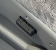
SYMPTOM TEST B: ONE BELT WILL NOT LEAVE FRONT BODY PILLAR (A-PILLAR)
Perform door latch switch component test. See DOOR LATCH SWITCH TEST . If door latch switch functions properly, go to next step. If door latch switch does not function properly, replace door latch switch.
Perform B-Pillar limit switch test. See B-PILLAR LIMIT SWITCH TEST . If B-Pillar limit switch functions properly, go to next step. If B-Pillar limit switch does not function properly, replace front seat shoulder strap track.
Perform safety belt retractor motor test. See SAFETY BELT RETRACTOR MOTOR TEST . If safety belt retractor motor functions properly, go to next step. If safety belt retractor motor does not function properly, replace front seat shoulder strap track.
Turn key off. Locate and disconnect passive restraint control module connector #2. Disconnect door latch switch connector. Measure resistance of Blue/Yellow wire (driver's side inoperative) or Blue/Orange wire (passenger's side inoperative) between passive restraint control module connector and ground. If resistance is greater than 10,000 ohms, go to next step. If resistance is not greater than 10,000 ohms, service/repair wire in question.
Turn key off. Disconnect passive restraint control module connector #1 (driver's side inoperative) or #2 (passenger's side inoperative). Disconnect B-Pillar limit switch connector on inoperative side of vehicle. Measure resistances of Yellow/Red wire (driver's side inoperative) or White wire (passenger's side inoperative) between passive restraint control module connector and ground. If resistances are greater than 10,000 ohms, go to next step. If resistances are not less than 10,000 ohms, service/repair wire in question.
Turn key off. Disconnect passive restraint control module connector #1 (driver's side inoperative) or #2 (passenger's side inoperative). Disconnect B-Pillar limit switch connector on inoperative side of vehicle. Measure resistances of Blue/Green and Brown wires (driver's side inoperative) or Yellow/Green and White/Black wires (passenger's side inoperative) between passive restraint control module connector and B-Pillar limit switch connector. If resistances are less than 5 ohms, replace passive restraint control module. If resistances are not less than 5 ohms, service/repair wire(s) in question.
DOOR LATCH SWITCH TEST
Turn ignition OFF. Disconnect door latch switch connector. Measure resistance between two terminals at door latch switch. With door open, there should be less than 5 ohms. With door closed, there should be greater than 10,000 ohms. If resistances are correct, return to SYMPTOM TESTS. If resistances are not correct, replace lamp switch.
A-PILLAR LIMIT SWITCH TEST
Turn ignition OFF. Disconnect A-Pillar limit switch connector. Measure resistance between two terminals of A-Pillar limit switch. With carrier at front body pillar position, there should be less than 5 ohms. When carrier is not at front body pillar position, there should be greater than 10,000 ohms. If resistances are correct, return to SYMPTOM TESTS. If resistances are not correct, replace front seat shoulder strap track.
B-PILLAR LIMIT SWITCH TEST
Turn ignition OFF. Disconnect B-Pillar limit switch connector. Measure resistance between terminal 7 and 6 at B-Pillar door latch switch. See Fig. 3 . With carrier at center body pillar position, there should be less than 5 ohms. When carrier is not at front body pillar position, there should be greater than 10,000 ohms. If resistances are correct, return to SYMPTOM TESTS. If resistances are not correct, replace front seat shoulder strap track.
SAFETY BELT RETRACTOR MOTOR TEST
Turn ignition OFF. Disconnect B-Pillar limit switch connector. Apply 12 volts to terminal 4 at B-Pillar limit switch. Ground terminal 1 at B-Pillar limit switch. The belt carrier should travel.

Tuesday, March 23rd, 2010 AT 2:09 AM


