Flashing security warning on dash, no crank, no click

1998 BUICK LESABRE
243,000 MILES • 3.8L • V6 • 2WD • AUTOMATIC
Avatar
ALPHAA10
  • MEMBER
  • 232 POSTS
Parked in front of a store during errands, I casually inserted the ignition key and tried to start. Nothing happened-- no click, no crank.
Sure that it was a starter problem on this aging sedan, I did all my research on starter and solenoid issues and repair methods. This morning, I was ready to start work on diagnostic tests.
However, as I tried a final check on symptoms, I found a security warning flashing at the upper right of the instrument panel. All the idiot lights also were on, but I had not registered the security warning until now.
According to what I have read, the first thing to do is to use a different ignition key, since the Hall Effect resistor on the original Buick key may have been damaged. However, that produced no results, and the security warning continued.
All other signs are normal-- strong headlights, a full battery charge (though no load test, yet), and the motor windows roll up and down.
Can you point me to an article 2CarPros has published on the security warning symptom?
Sep 13, 2021 at 8:30 PM

Advertisement
Avatar
DANNY L
  • Experienced Mechanic
  • 5,648 POSTS
Hello, I'm Danny.

First thing I would suggest is to perform an anti-theft, security system reset. Here is the tutorial showing how to reset:

https://www.2carpros.com/articles/how-to-reset-a-security-system

Scroll the page to find the additional GM instructions.

I am also attaching all the info from the manual that includes some flow charts that are for the theft light staying on all the time or flashing.

So let's run through all this info and go from there.

Hope this helps and thanks for using 2CarPros.
Sep 13, 2021 at 9:55 PM
Avatar
ALPHAA10
  • MEMBER
  • 232 POSTS
I have tried several of the OEM VATS system reset procedures in this article--
https://www.2carpros.com/articles/how-to-reset-a-security-system

1. Driver's door key reset-- tried this several times, using the side lock entry key to reenter after locking all doors and exiting car, waiting at least 15 minutes while more than 10 feet distant.
2. Activate key fob-- this involves pressing the panic button, and I wanted to disable the horn, first, to avoid antagonizing my neighbors. Searched and found the horn relay in the Maxifuse box, but having trouble opening the two black plastic thumb-style connectors, one on either side of the fuse box. Do these connectors slide open, or should I twist, then try to slide them open?
3. Turn ignition on-- inserted and turned ignition key, tried to start, and left key in on for about 10 minutes-- the flashing security warning did not stop flashing after even 20 minutes. After the first cycle, in which the flashing warning did not disappear, I repeated the sequence, allowed 20 minutes, and the warning continued without interruption.
4. Remove alarm fuse-- this is a simple procedure, but I am waiting for an answer to question 2, so I do not break the access connectors.
5. Disconnect battery-- Sears installed battery, but with a side terminal connector which appeared to have been rounded off, so there is no reliable way to turn the connector without using vise-grip pliers. The concern is not removal of the connector, but the purchase of a new connector, first. The whole procedure takes only a few minutes.
Sep 22, 2021 at 7:54 PM
Avatar
JACOBANDNICKOLAS
  • Experienced Mechanic
  • 110,240 POSTS
Hi,

I noticed we haven't heard from you for a couple of days. Has any new progress been made? We are interested in knowing.

Also, the side mount battery terminal replacements are easy to find. Most parts stores will have them in stock.

I attached a pic below of what I believe you need.

Let me know.

Joe

See pic below.
Sep 25, 2021 at 4:06 PM
Avatar
ALPHAA10
  • MEMBER
  • 232 POSTS
Had you checked your email inbox? I sent my latest response September 23, according to the date line below my message text. Read that over, for my status as of last Thursday.
This past Saturday, September 25, I completed every technique 2CarPros suggested to bypass the GM security lockdown-- but the flashing "Security" warning continues.
Thanks for your suggestion for the part I need, but I already have purchased the battery terminal bolt (set of 2), and all on that concern has been taken care of.
If you refer to the original article I was given to read, to defeat the security lockdown, there are detailed procedures involving the valet key, the ignition key fob, the VATS fuse and disconnection of the negative battery terminal. In each case, I was careful to follow instructions carefully, but got no improvement in the situation.
During use of the ignition key technique, I attempted to start, and left the key in the ON position for 15 minutes. At no time did the security warning disappear.
During use of the valet key technique, I opened the car, rolled up all windows, made sure the trunk was secure, and relocked the car with the valet key. After waiting (with my key fob at least 20 feet away from the car for about 15 minutes, I opened the car with the valet key, but the security warning was still present.
Next, I withdrew the VATS alarm fuse (20a), and after about 15 seconds, reinserted it, but for no change the security warning.
Finally, I disconnected the negative battery terminal, installed the new battery terminal, but for no change in the security warning.
Today, I plan to try the resistor technique. Cutting into the VATS signal line (orange wire) running from the ignition to the general terminal connector assembly, The VATS signal line has two white wires, one from the below-dash terminal to the ignition, and the other from the ignition back to a second connector on the below-dash terminal. The idea is to make a short-circuit between the two below-dash attachment points, and solder into that short wire length a resistor rated at the Ohms of the pellet-based ignition key. In my case, my ignition key pellet displayed 1860 Ohms on my VOM, for which I plan to use a 2000 Ohm resistor.
Throughout, I have presumed my nightly charging of the battery would keep the battery at operating level, capable of a full l starting load. Each morning, when I have checked the battery maintainer, its LED glows green, to show a normal charge has been achieved and is being maintained. However, a charged battery is not necessarily capable of a full starting load. For that reason, I plan to take the battery today to a local auto parts store for a load test.
Summary
1. Install the appropriate resistor in the VATS ignition signal line.
2. Load test the existing 2-year old battery. (Walmart type 78S)
Sep 25, 2021 at 6:41 PM
Avatar
JACOBANDNICKOLAS
  • Experienced Mechanic
  • 110,240 POSTS
Hi,

If you emailed him, chances are that is why he didn't realize you responded. Your summary indicated VATS resistor and a load test. Are these two things still needing to be done?
Sep 26, 2021 at 12:12 PM
Avatar
ALPHAA10
  • MEMBER
  • 232 POSTS
Response was sent as a reply to this original thread (above), dated September 23. My reference to "inbox" had to refer to this thread, because I do not have his email address.

In answer to the two questions, the battery load test was performed yesterday by Advance Auto, and the battery passed the test. A 2,000 Ohm VATS resistor will be installed ASAP, probably tomorrow.

Appreciate your follow up.
Sep 27, 2021 at 8:29 PM
Avatar
JACOBANDNICKOLAS
  • Experienced Mechanic
  • 110,240 POSTS
Hi,

Thanks for the update. If you have a chance, let us know if the resister takes care of the problems. We are interested in knowing.

Take care,

Joe
Sep 28, 2021 at 11:20 AM
Avatar
ALPHAA10
  • MEMBER
  • 232 POSTS
Hi,

As I prepared to cut the ignition security sensor (orange) cable this afternoon, I discovered there seems to be two orange wires under the dash. One orange wire runs from the below-cash connector assembly (located to the right of the below-dash fuse box, and directly below the steering column), and the other orange wire seems to emerge from behind the main wire mass/bundle, upward, toward the ignition switch. Now that I reconsider, this could be the same orange wire, seeming to run upward, then looping down into my view, before disappearing upward again, to connect with the ignition switch.
Until I take apart more of the under-dash panels, I cannot say, at this point.
I have included two photos for your comment.
Sep 30, 2021 at 7:17 AM
Avatar
JACOBANDNICKOLAS
  • Experienced Mechanic
  • 110,240 POSTS
Hi,

I attached the wiring schematics for both the pass key circuit and the forced entry circuits below.

Pic 1 and 2 are the forced entry circuit. I'm seeing one orange wire that supplies power to the remote actuator module. There are a few that are orange with a black tracer, but the pic appears to be solid orange.

Pics 3 and 4 are for the anti-theft pass key circuit. There are no orange wires.

Follow the orange wire and see if it goes to the right-side instrument panel fuse box.

Let me know.

Joe

See pic below: Note I had to cut each schematic in half to make them readable for you. I did overlap them so you can follow from one to the next.
Sep 30, 2021 at 11:41 AM
Avatar
ALPHAA10
  • MEMBER
  • 232 POSTS
Pics 3 and 4 for the anti-theft passkey circuit are the only diagrams that seem to apply to VATS and the ignition pellet key. Soon, I'll send photos of the actual wiring beneath the dash, in all their glorious colors (including orange) and all rendered in sharp focus.
Sep 30, 2021 at 2:18 PM
Avatar
JACOBANDNICKOLAS
  • Experienced Mechanic
  • 110,240 POSTS
Hi,

Sounds good. If there is a specific circuit you want me to look for, let me know.

Take care,

Joe
Sep 30, 2021 at 2:40 PM
Avatar
ALPHAA10
  • MEMBER
  • 232 POSTS
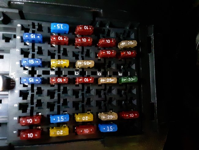
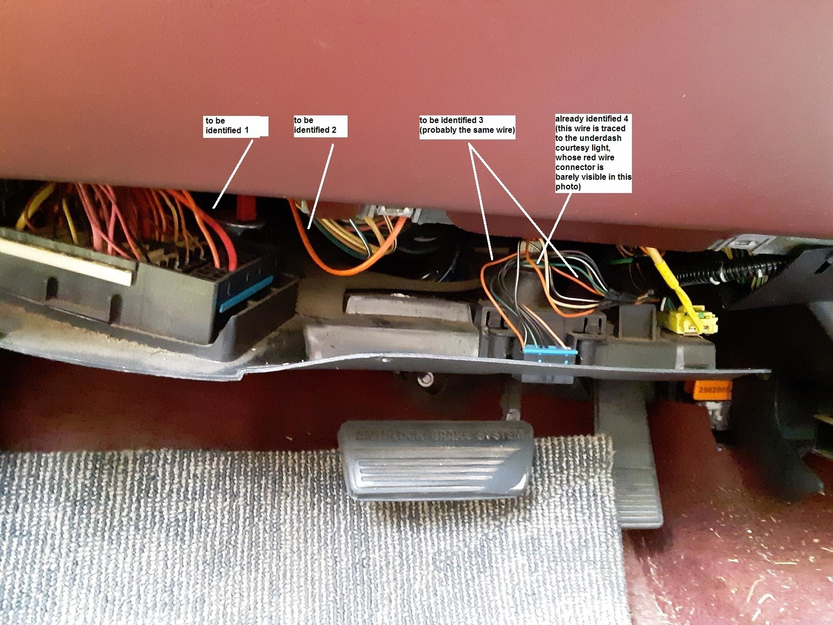
Here is a photo of the under-dash fuse panel, and a frontal view of under-dash wiring. I hope to select the correct orange wire which controls the VATS system from the ignition key. As you will see immediately, these photos are much better quality than the two (above) which were sent earlier.
In the photo of under-dash wiring, I have drawn arrows to the prospective orange wire to be cut. Regarding "To Be Identified" orange wires 3 and 4, they emerge from the same black tape-wrapped wire bundle (to the left of the airbag's yellow wire). Wire 4 has been traced to the under-dash courtesy light (with small red plastic connector), and Wire 3 runs from the wire bundle to the EBD socket. From the photo, alone, neither of those seems part of the VATS ignition wire circuit. Your wiring schematic 3/4 may have clues I missed.
Your own confirmation/advice will make the critical difference before I cut any orange wire. Of course, I could cut by trial-and-error, but rather would plan ahead, than regret, later, when possible.
In the photo of the interior fuse panel, I provide you a reference photo for other questions, later, if the orange wire trick does not work.
Oct 1, 2021 at 6:51 AM
Avatar
JACOBANDNICKOLAS
  • Experienced Mechanic
  • 110,240 POSTS
Hi,

The vats schematic doesn't indicate any orange wires, which is confusing me. I tried looking through the power distribution schematics (6 pages long) and there must be a hundred orange wires, none of which are related.

In the pic, the left wire appears to be going to a fuse box. What fuse is it powering? Also, since I don't have a schematic specific to the ignition switch, the best thing to do is follow the wire to see if it goes to the switch. It's near the bottom of the steering column. See pic 1.

Not being there is making me nervous to indicate which to cut. I don't want to arbitrarily pick one and be wrong causing you more work. I hope you understand.

Let me know.

Joe
Oct 1, 2021 at 1:22 PM
Avatar
ALPHAA10
  • MEMBER
  • 232 POSTS
Joe, thanks for the continued effort. As a (computer) tech support person, myself, I fully understand the task can be difficult. However, to be clear, I ask for only your advice, not to have you make the decision for me.

The immediate problem is to determine which orange wire leads to the ignition VATS module. What I plan to do is take apart the dash further and see whether I can trace physically the orange wire. Later, perhaps I can send a better photograph of the wiring paths.

Ideally, if I were able to go further into the steering column, I could do a continuity check between each of the orange wire(s) at the subdash connector panel and any orange wires going into the actual ignition switch area.

QUESTIONS--
Question 1-- Based on your reading of the ignition schematic, could the orange wire identified in my subdash wiring photo as wire 3, starting in the on-board diagnostics (EBD?) socket assembly, be involved in the VATS security system? If not likely, that leaves orange wires 1 and 2 as the only prospects, for now.

Question 2-- Is there any reason to leave the yellow airbag wire connected during my wire tracing movements? I don't want to strain the cable, and disconnection would prevent cable damage until I am ready to reconnect everything. However, you have more experience with the airbag circuitry than I, so I need to ask. Obviously, I don't want to trigger the airbag during my work (nor on re-connection of the airbag circuit connector).

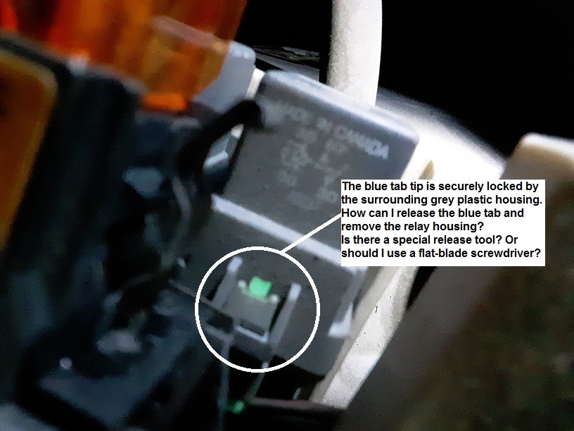
Question 3-- Looking ahead, how can I release the starter relay retainer clips-- one each each side of the relay? I don't want to break the aging plastic retainer clips. Obviously, I cannot simply pull off the relay housing cube with a large-span pair of pliers (Channel Lock or Vise-Grip). Would you insert a flat-blade screwdriver beneath the clip? Is there a special puller for a plastic cube relay? Do you need a photo?

Question 4-- Fuse Panels
While the shifter was in PARK and ignition was on (all warning lights on), but the key released from its start engine position, I checked the interior subdash fuse panel fuses with a circuit/continuity checker. All of row 2 fuses (A through E) are off/out when I touch the two contacts on each fuse. (Since all row positions 2A-2E are labeled "spare", that presumably means they are not connected to any circuit). Fuse 2E, according to the Fuse Usage label on the fuse panel cover, is a red 10a spare for "AIRBAG/VATS". Of all active fuses in the panel, there is only a single fuse labeled "VATS" on row position 1A, and that fuse is on when I touch each of its two contacts with the circuit tester.

I have not yet checked the Maxifuse panel above the engine but have succeeded in opening the fuse panel cover without breaking the white, twist-open plastic connectors. My next step is to check all fuses in that panel, as well as its relays.
4a-- Should I switch the ignition key on during that fuse panel check?
4b-- What about the relays-- is there any way to check them without pulling the plastic cube from the panel for a physical continuity check?

Question 5-- when working to resolve a VATS lockdown, have you ever encountered a vehicle which did not work with any of the steps in the article 2CarPros offered here?
https://www.2carpros.com/articles/how-to-reset-a-security-system

Again, thanks for staying with this effort.
Oct 1, 2021 at 8:20 PM
Avatar
ALPHAA10
  • MEMBER
  • 232 POSTS
Still facing the flashing security warning, which indicates I have not defeated the security lockdown, and am still looking for the switch or condition responsible. Tomorrow, I take apart the dash further, so I can trace the under-dash wiring, and identify which of several orange wires is the ignition key resistance signal line.
As of this evening, I have tested all fusible links (both fuses and Maxifuses) with the ignition key on, and all are okay. Pending your answer to my question (above) about how to remove a relay which has retainer clips, I can remove and test all six of the under-hood relays with a circuit continuity checker. I realize, of course, a starting circuit relay does not seem directly related to a security lockdown condition, but it is one of the pre-diagnostic steps recommended by the OEM.
For your convenience, I have numbered the important issues and questions in the previous message. I encourage you to comment on each in as much detail as you like.

Today, I bought and downloaded a PDF of the GM service and repair manual for the Buick 1992-1998. After a brief look inside, I realize this may be the same resource you use. If this manual is also your own resource, you can refer me to a particular page (appreciate all the attachments you have provided with your messages and comments).
Oct 2, 2021 at 11:14 AM
Avatar
JACOBANDNICKOLAS
  • Experienced Mechanic
  • 110,240 POSTS
Hi,

It sounds like we have our hands full. LOL I looked at the schematic again. There are three fuses related to VATS. See picture one below. Note, the pcm/vats fuse goes to the anti-theft control module. The interesting one is the airbag/vats fuse. I noted that it only gets power in the start position and in turn, it signals the theft deterrent relay under the dash.

Recheck those.

Now, with regards to your questions, see below.

Q1 -- I looked through the schematic again. At this point, I don't feel it could. I looked through the power distribution schematics and found one orange wire going to the DLC. See pics below. Note: I cut each of the six pages in half to make them readable. I did overlap them. If you look at pic seven below, I highlighted the DLC, wiring, and fuse. Unless that wire is spliced, I don't think that is the source. Take a look through the schematic (it's somewhat large) and note how many orange wires were used. LOL

Q2 -- As far as the airbag, you can disconnect it. However, it is very important to have the power disconnected both when disconnecting and reconnecting it. I always tell people to disconnect the battery for at least 30 minutes before working on it. You can remove the fuse as well. We just need to take the power away.

Q3 -- I think you are referring to the starter enable relay. Take a look at pics 13 and 14. Those are the directions. If it is something different, let me know.

Q4 -- Fuse 2E is the starter enable relay fuse. That should have power in the start position. See pic 15 below. Note: I crossed out "Oldsmobile" because I believe that is a reference to the instrument cluster since it follows it.

Q5 -- The answer to Q5 is yes. The reset provided is a general reset. It works with many vehicles but not all.

Let me know if any of this helps.

Take care,

Joe

I just realized I forgot to add pic 1. It is now the last on the page. Sorry.
Oct 2, 2021 at 12:35 PM
Avatar
ALPHAA10
  • MEMBER
  • 232 POSTS
Thanks, Joe-- all your answers help. Below is my effort to understand your answers completely.

Q1-- Diagnostics port orange wire--
"DLC" means diagnostics port?
There are almost too many orange wires to count, which is the primary reason for going further into the dash wiring.

Q2-- Airbag cable and fuse 2E--
Since fuse 2E is labeled Airbag/VATS, can I do all sub dash and under-hood work with the airbag fuse removed, and with the yellow airbag cable disconnected?
That is, if fuse 2E controls VATS, as well, could that pose a problem?
> As I read your reply, so long as I am careful to disconnect both battery and fuse 30 minutes before removing the airbag cable (yellow) and the airbag fuse, I should be okay.

** On reconnection of battery and fuse 2E, I now understand I must connect the fuse and airbag (yellow) cable before reconnecting the battery. (Appreciate the warning about a surge and accidental airbag deployment)

> My urgent question about fuse 2E is whether this Airbag/VATS fuse 2E-- if bad and/or loose in its socket-- could trigger the Security warning and VATS lockdown. The red 10A fuse fits very poorly in its socket. I cannot feel a solid insertion when I press on the fuse top, so it may be going in crookedly. As your diagram #15 indicates, the fuse must be tested in ignition position start to be active. (Of all sub dash and under-hood fuses, this is the only active (non-spare) fuse on fuse row 2.)
> Since the ignition switch must be in start position to test fuse 2E, must I have somebody else to turn the ignition key while I probe the fuse? Without a remote starter cable, is there another way for me to switch the ignition key with one hand, and probe 2E with the tester? Incidentally, with the ignition key in "run" (but not start), I have no light on my continuity/circuit tester, which is expected.


Q3-- Starter enable relay--
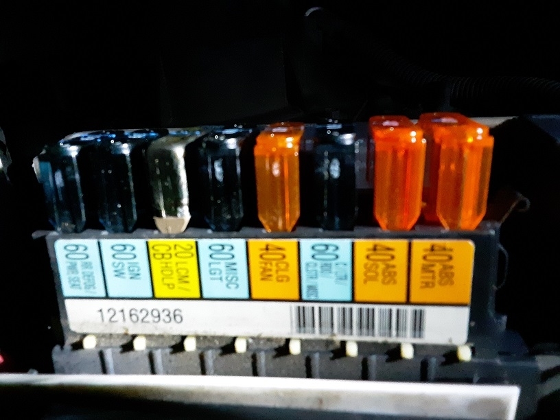
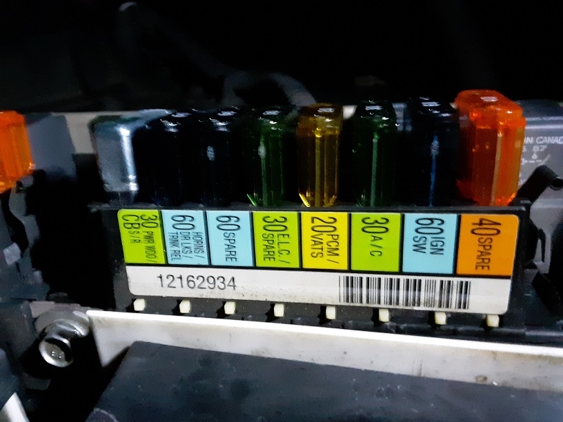
Except for the starter enable relay, located under dash, relays are located in the under-hood fuse blocks (left and right). For your convenience, I have attached a photo of the row of under-hood relays, so you can see why I am puzzled by physical removal difficulty. I have not been able simply to pull the relay cube housing outward, despite wiggling it.
> Could a Security lockdown warning be triggered by a faulty starter relay? I realize the PCM is the source of all security actions but did wonder.

Q4-- "Starter enable relay fuse 2E"--
> I was not aware the starter enable relay had a fuse. Fuse 2E is labeled Airbag/VATS on the fuse cover inside label.
> On the relay, itself, I plan to test ASAP, although my attention has been focused on the VATS warning. As in Q3, above, I still need to determine how to remove the relay from its socket, it order to test the relay on all its contact points. Even if the relay clicks when power is applied, could it still be faulty?


Q5-- Security system reset failure--
Have you heard any comments about this PCM bypass device? --
https://duckduckgo.com/?q=rockies+ignition+bypass&atb=v293-3&ia=web

Since I doubt, I can afford this device ($297.00), I wonder what other bypass devices for the PCM are on the market. When I searched, I did not find any, which explains the high price of the device.

Oct 3, 2021 at 9:11 AM
Avatar
JACOBANDNICKOLAS
  • Experienced Mechanic
  • 110,240 POSTS
Hi,

There are too many orange wires. They go in every direction. LOL

Yes, the DLC is the data link connector used for diagnostics.

Before we do anything else, I need you to go back to fuse 2E. You indicated it doesn't feel correct when inserting a fuse and there is no power evident. Inspect the terminals to make sure one hasn't pushed inward preventing it to attach to the fuse.

Also, before you reconnect the battery, the fuse and connector to the airbag should be installed/connected. You don't want it disconnected and receive a power surge after the battery has been connected.

Let me know about the fuse.

Take care,

Joe
Oct 3, 2021 at 10:01 AM
Avatar
ALPHAA10
  • MEMBER
  • 232 POSTS
Your answer arrived just as I revised and sent to you my latest message, above, timed 4:11pm. Please look over the revised message, and I'll concentrate on the fuse 2E. If I find a 2E socket problem, can that fuse socket be repaired from beneath the dash? I may have to remove the entire fuse socket panel/block.
Summary--
1. Check fuse 2E
2. Send to you a photo of the under-hood relays, and a close-up of their plastic housing retainer clips.

Thanks, Joe.
Oct 3, 2021 at 10:14 AM
Avatar
ALPHAA10
  • MEMBER
  • 232 POSTS
Joe,

As promised--
1. Fuse 2E is okay on both contact points-- somehow, I was able to hold the probe with one hand and try to start the engine with the other hand.
2. Attached are photos of the left and right under-hood Maxi fuse and relay panels. And a photo of the starter relay plastic housing clip that resists being opened. On that, I need to know how you would pull out the relay-- use a special tool, or continue pulling and wiggling?
Oct 3, 2021 at 2:30 PM
Avatar
ALPHAA10
  • MEMBER
  • 232 POSTS
Here are the photos. From left to right.

1. under-hood relay, showing blue plastic retainer clip.
2. under dash Maxi fuse and relay panel, left.
3. under dash Maxi fuse and relay panel, right.
Oct 3, 2021 at 3:04 PM
Avatar
JACOBANDNICKOLAS
  • Experienced Mechanic
  • 110,240 POSTS
Hi,

The blue tab will slide upwards. You don't need to fully remove it. It simply is a locking device to prevent the connector from coming apart. If you can't move it by hand, try a straight screwdriver.

Now, if fuse 2E is good, then we need to check if the power makes it to the theft deterrent relay via a purple wire. I have a feeling you will need a helper for this. Again, it will only get power when the key is in the start position.

See pic below

Let me know what you find.

Joe
Oct 4, 2021 at 12:33 PM
Avatar
ALPHAA10
  • MEMBER
  • 232 POSTS
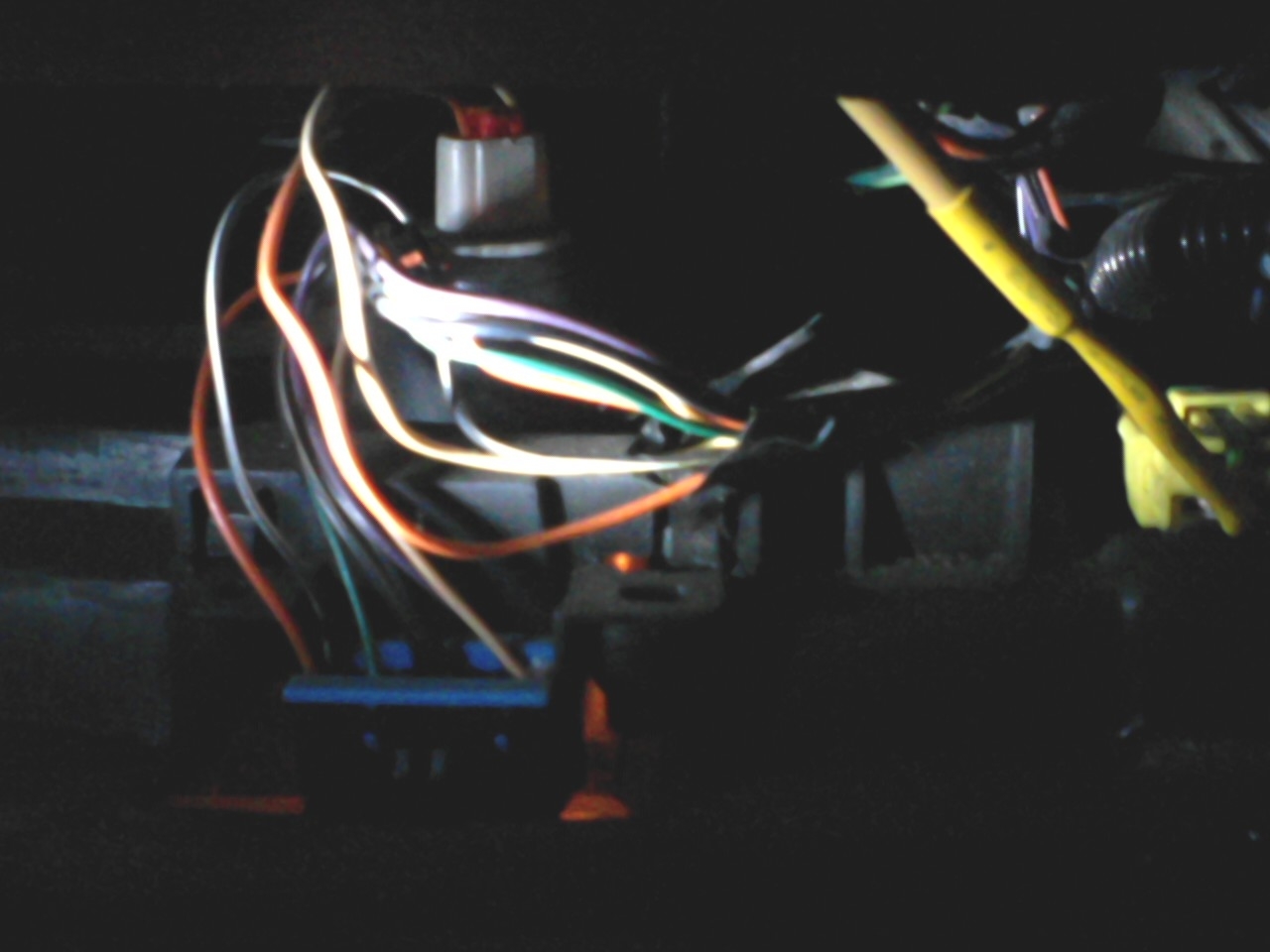
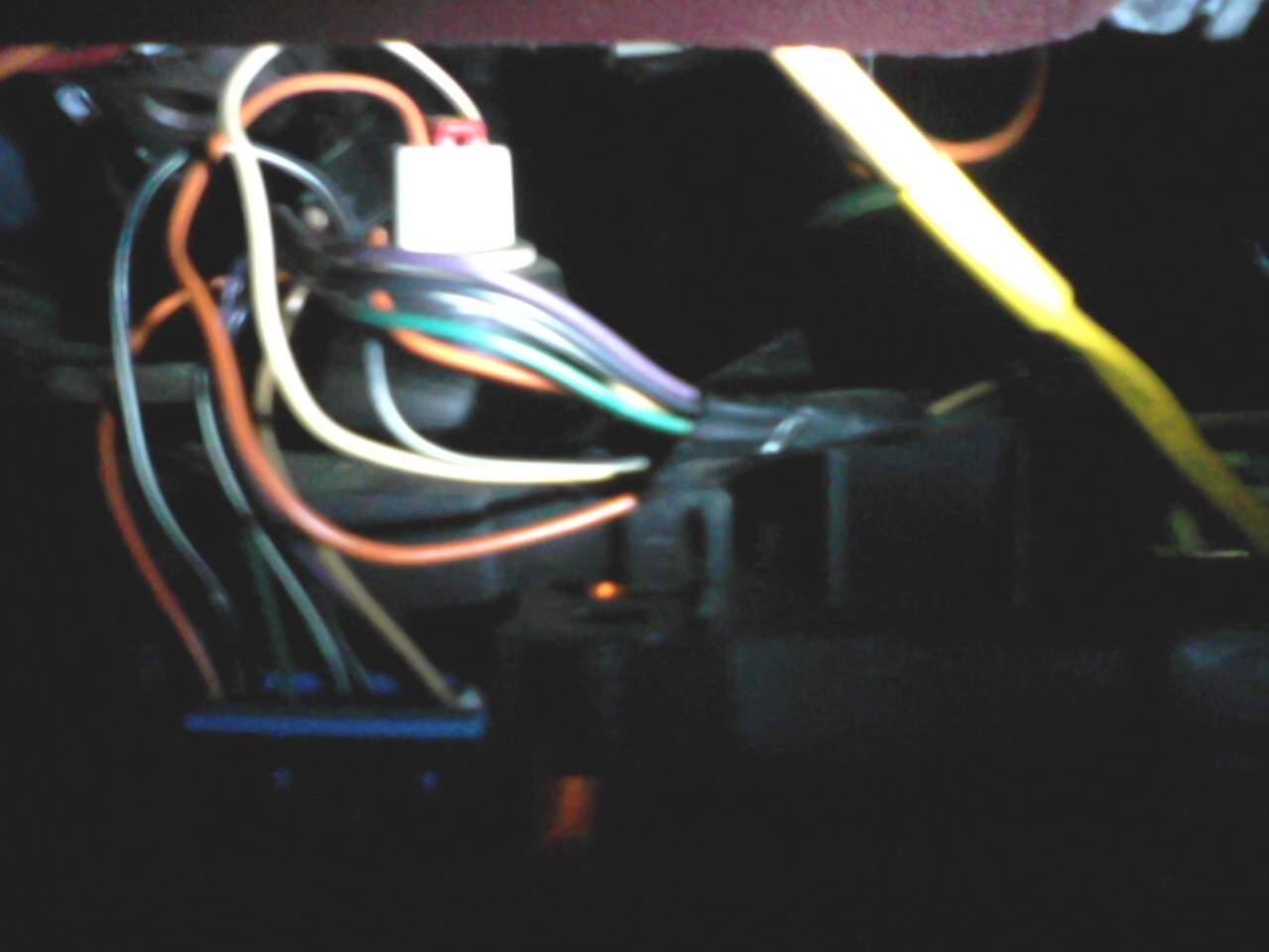
Joe, late this afternoon, I may have found the elusive orange wire. After watching a few YouTube videos showing the resistor bypass technique, in which one of them briefly showed the under-dash area where the orange wire runs, I located the same area and the most likely candidate orange wire.
Not only that, but all the videos show the correct orange wire is actually an orange jacket containing two white-jacketed wires. It became a simple matter to identify the correct orange wire by its oval (oo), rather than round, cross-sectional shape. Fortunately, there is only one oval orange wire in the sub dash area of interest.
Eagerly, I finger-traced the oval orange wire to the junction block above the left under-dash fuse panel. At that location, the orange wire opens into two smaller, white wires, each of which disappears into the junction block.
As I tried to photograph the wire, rain began, but soon, I hope to attach the photos I was able to take of the orange wire and its surroundings. As soon as the rain ends (for a while), I can experimentally attach the resistor, leaving enough of the original orange wire hanging from the junction block for easy reattachment, if the plan fails. Is that a promising approach?
Oct 6, 2021 at 3:26 PM
Avatar
ALPHAA10
  • MEMBER
  • 232 POSTS
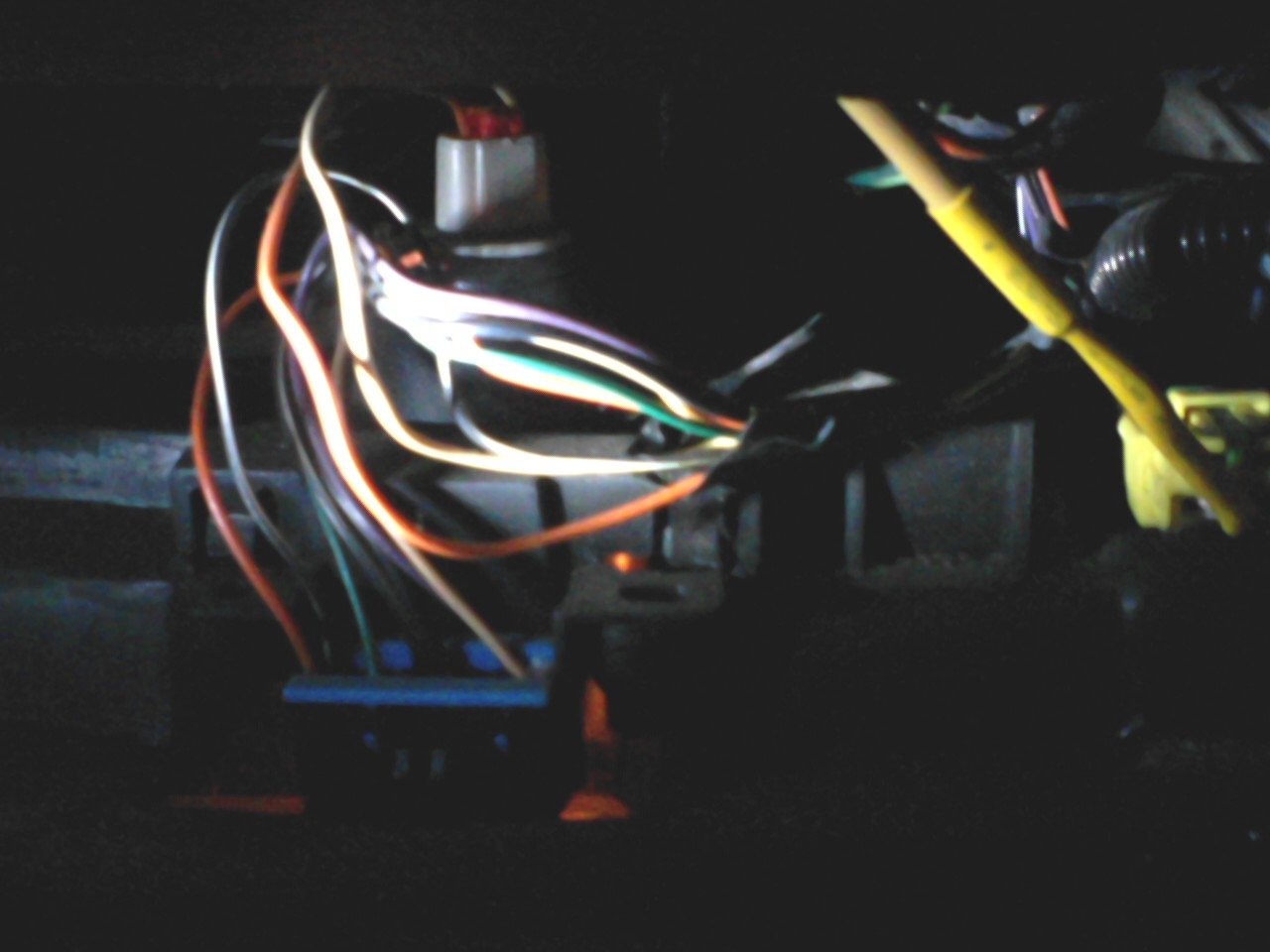
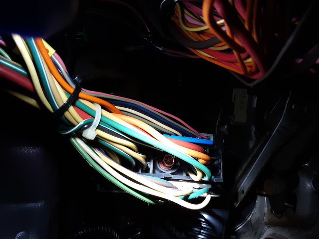
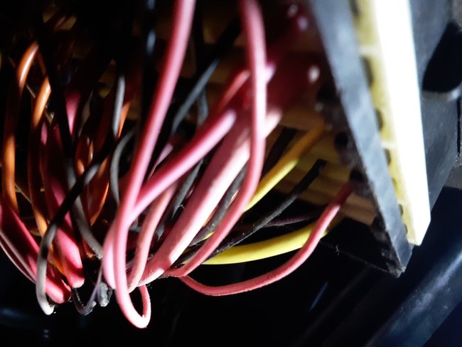
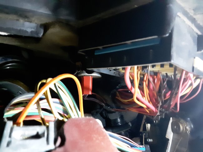
Photos, left to right, were taken from an upside-down position, with my head below the dash, and trying to hold the flashlight beam steady with one hand, while keeping the camera focused on the area of interest with the other. For that reason, some of the photos may be considered upside-down, so you can flip or rotate them in your viewer to make them clearer.

1. Photo (correct orientation) of orange oval wire emerging from dark background, and entering into a flexible, black plastic conduit running upward into the ignition switch.
2. Photo (upside down) of oval orange wire entering the junction block. Nearby, the solid purple wire you mentioned enters a blue-plastic framed portion of the junction block.
3. Photo showing solid purple wire emerging from the back of the fuse panel. On the other side of the panel is fuse 2E. The circuit tester did not blink on when I probed the same purple wire at the junction box as I turned the ignition key, but I'll try to confirm that.
4. Photo (upside down) of orange oval wire looping down. In this photo, its oval cross-section is visible as a sharply defined reflection line.
Oct 6, 2021 at 5:52 PM
Avatar
JACOBANDNICKOLAS
  • Experienced Mechanic
  • 110,240 POSTS
Hi,

Looking and thinking, it should be okay to try. However, you indicated there is no power via the purple wire. That should be coming from fuse 2E. I read a more detailed section of the schematics and found it should have power in run and start positions.

Are you able to trace that purple wire back to the fuse to see if or where power is lost?

Joe
Oct 7, 2021 at 7:24 AM
Avatar
ALPHAA10
  • MEMBER
  • 232 POSTS
In your October 4 message, you provided (thank you) a schematic for the connection from fuse 2E to the Theft Deterrent Relay. The fuse block shows 2E is hot in start but says nothing else about other hot positions for 2E, ie, nothing about run. Did I read that schematic incorrectly?
When the rain stops, I'll first check for 2E (purple wire) power to the junction block (located to the left and above the fuse panel). And make sure to determine whether 2E power is present for start and also run.
Oct 7, 2021 at 6:08 PM
Avatar
JACOBANDNICKOLAS
  • Experienced Mechanic
  • 110,240 POSTS
Hi,

That is what the schematic indicated. I read through a different one that indicated power in both the run and start position.

Let me know if you have questions or if I can help.

Joe
Oct 8, 2021 at 10:22 AM
Avatar
ALPHAA10
  • MEMBER
  • 232 POSTS
Still working on the problem. will have information, soon.
Oct 8, 2021 at 12:13 PM
Avatar
ALPHAA10
  • MEMBER
  • 232 POSTS
Today, my battery charger expired, so Sunday, or Monday, at the latest, it will be replaced. That will permit me to resume testing the path for fuse 2E.
Oct 9, 2021 at 2:01 PM
Avatar
JACOBANDNICKOLAS
  • Experienced Mechanic
  • 110,240 POSTS
Hi,

No problem. Let me know what you find when you can.

Take care,

Joe
Oct 9, 2021 at 2:29 PM
Avatar
ALPHAA10
  • MEMBER
  • 232 POSTS
Good news, Joe. the car started after I installed a 2kOhm resistor across the orange sensor data line to the PCM. (Using shrink tubing, I sealed off each of the two-cut wire ends of the orange line running up into the ignition switch.)

All fuses are intact, including 2E, and the Maxi fuses are okay, too. Obviously, all the relays work, as well. Starting is not a problem, and current battery voltage is 12.78v, and the charging voltage from the alternator (measured across battery terminals) is 14.11v.

Joe, this problem resolution would not have been possible without your staying with me as I worked through the diagnosis. As you know, not all VATS problems yield to a simple resistor. Reviewing all my previous messages, you can see how you helped the diagnosis progress in a systematic and logical fashion.

Because of your help, I acquired a good basic working knowledge of the Buick electrical system, and the VATS system, in particular.

Yours has been a sustained and very helpful effort, and I thank you sincerely for your dedication and professional service.

--------------------------
* I have two more questions, but unrelated to the VATS issue. Should I submit these the same way I entered the VATS question?
1. Where can I find a 1998 Buick LeSabre 3.5L engine plenum intake which is made of metal? This model Buick, by all sources I have read, comes with an OEM plenum made of PLASTIC, and plenum failure can ruin the engine.
2. Does 2CarPros have a video on changing the accessory belt on a 1998 Buick LeSabre 3.5L engine? There is only a 2CarPro video that is very general.
Oct 10, 2021 at 8:15 PM
Avatar
JACOBANDNICKOLAS
  • Experienced Mechanic
  • 110,240 POSTS
Hi,

I'm really glad to hear it's running again for you. Electrical issues can be a nightmare. Also, you don't have to thank me. You did all the work and we learned from each other. Thank you for that.

As far as a video, there isn't one specific to your vehicle. However, we do have directions and pics. Also, the intake being plastic wasn't a good idea. I agree with you. They try to eliminate weight to better the vehicle's performance, but that often leads to less dependability.

If you want to ask those two questions, start a new thread. We try to keep these specific to one topic, so they help others easier. I hope you understand. Here is the link to start a new question. Simply copy and paste your questions to a new thread. I hope I see it before others. LOL Regardless, they will get answered.

https://www.2carpros.com/questions/new

You take good care of yourself, and please feel free to come back anytime in the future if you have questions or need help. You are always welcome here and are now simply a part of the family. LOL

Take care,

Joe
Oct 11, 2021 at 12:33 PM
Avatar
ALPHAA10
  • MEMBER
  • 232 POSTS
Joe,
You may not remember me, but about 18 months ago, I had worked with you on a VATS problem. It was resolved, and I drove happily until recently-- into a new no-crank situation. I have isolated the problem to the starter solenoid circuit, either the starter relay or the fuse 2E on the MiniFuse panel.

My reason for RE-contacting you is we had discussed MiniFuse 2E before-- it did not feel secure as I pushed on it from the top. You commented that insecure feeling means the fuse may not be inserted properly or something else is wrong with the fuse or its socket, and probably should be checked again.

So, now the question-- after running normally for 18 months, the car no longer will crank. On inspection, I discovered MiniFuse 2E appears to be missing, altogether. When I checked more closely, I found the entire MiniFuse 2E red cap (labeled "10A") from the MiniFuse 2E has dropped off, along with much of the original two fuse blades. I vaguely recall finding a minifuse red cap on the floorboard, but thought it was only debris from previous work-- little realizing that was the missing red cap. In spite of the missing red cap, the fuse apparently continued normal crank operation until now.

On re-examining MinuFuse socket 2E, I found both blade sockets are occupied by stumps of the original two blades. Since fuse 2E is on the starter solenoid trigger circuit, that could explain my no-crank problem.

The problem is how to remove the two metal stumps. To gain more access to the lower dash shroud containing the MiniFuse panel, I must disconnect the yellow airbag cable. Previously, you had said this can be done, provided I make sure the battery is not connected before the airbag cable is reconnected (otherwise, risking airbag deployment). There is also another set of wires that must be disconnected, but that seems relatively simple.

With the airbag cable disconnected and lower dash shroud more accessible, I surely would be able to see the minifuse panel more clearly, and explore methods of removing the two metallic stumps. My problem at that point is how to pull the stumps out of the socket, or failing that, to push them out with a slender pick from the socket backside. On preliminary attempts, while the lower dash shroud is still fully connected, I tried to pull the stumps with slender needle-nose pliers, but cannot grip the longest stump, so have not even tried the other stump.

On trying to back-probe socket 2E, I could not insert even the slimmest of my small pick tools past the occupying wire and its connector. * BTW-- Do you know whether a "puller" is available for removing MiniFuse socket wires from the socket back side?

If that does not work, I guess I could snip the two wires going into socket 2E, and solder them to a regular 10A MiniFuse. From prior notes, one of the socket 2E wires is a thick, white wire, and the other is a slim, dark-brown wire. Both wires clearly enter the back of socket 2E.

What do you think about the proposed plan?
Jul 19, 2023 at 9:11 AM
Avatar
JACOBANDNICKOLAS
  • Experienced Mechanic
  • 110,240 POSTS
Hi,

I'm wondering why the fuse came apart. Does it appear as though it was overheated? Also, your idea of simply using an inline fuse would certainly work. If the fuse cover appeared melted, you may have a weak connection causing heat. That may or may not be repairable.

Is it possible for you to take a pic of what you are trying to remove? Also, if you disconnect the battery, it will help prevent anything from shorting when working in the box.

Let me know.

Joe
Jul 19, 2023 at 1:05 PM
Avatar
ALPHAA10
  • MEMBER
  • 232 POSTS
Thanks for responding, Joe. I had no other way to contact you directly on this matter we had discussed before. .

My best theory for the missing Minifuse--
When I originally mentioned to you MiniFuse 2E was reluctant to insert all the way into its socket, I removed it and tried reinsertion. The situation was no better, but the car started normally.

At that time, I had not looked inside the socket before I reinserted the fuse, but now I suspect the metallic stumps were already present in the socket, a remnant of someone's previous work on the car. The stumps had prevented full insertion, which accounted for the strange feel during insertion.

According to my theory, when I discovered a red-capped 10A MiniFuse on the floormat, I presumed the fuse was a left-over from previous maintenance. Since I never had seen a MiniFuse fall out, I did not check the MiniFuse 2E location in the MiniFuse panel. If I had, I would have noticed the fuse was missing. More than likely, during constant use, the fuse simply worked its way loose during its cooling cycle, after I had parked the car

This suggests I can insert another fuse, and successfully start the engine, which seems preferable to butchering the MiniFuse panel to remove the mysterious metal stumps I'll let you know what happens.

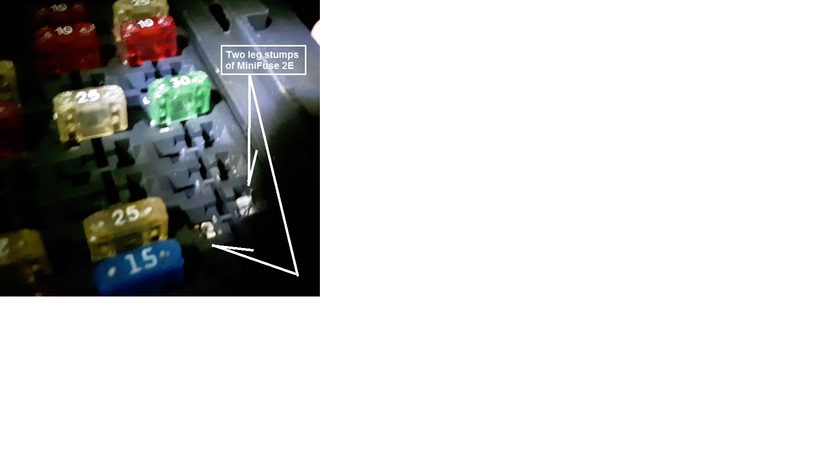
(Photo attached below-- the arrowed, white areas are simply metallic stumps, as best I can determine)
Jul 20, 2023 at 6:13 AM
Avatar
ALPHAA10
  • MEMBER
  • 232 POSTS
This afternoon, I tried to insert a 10A MiniFuse into socket 2E, but I met mechanical blockage. Despite the restrictive viewing angle, I saw enough to guess the socket seems blocked by the two bright metal objects you see in the photo.
Although I had interpreted the two metal objects as "stumps" of the original fuse, it is also possible the two metal objects are the original DC contact points for socket 2E.
If I am correct, that means I must use a small, straight-bladed screwdriver to open the contact points enough to admit the MiniFuse.
Why the fuse fell out is still a mystery, but if the socket were so mangled as I now suspect, any MiniFuse could fall out.
To provide a better working angle, I may remove the airbag cable and other, adjacent wires. This will permit me to move the right end of the lower dash shroud toward the firewall, while the MiniFuse panel swings toward me. That is the hope, anyway.
* Yes, I plan to take the precaution of disconnecting the battery before doing any work with the circuit. And before reconnecting the battery, I must make sure the airbag cable and all other cables have been properly connected.
Jul 20, 2023 at 10:19 AM
Avatar
ALPHAA10
  • MEMBER
  • 232 POSTS
Joe, you will be pleased to know the problem has been resolved.
1. Apparently, the 10A red-capped MiniFuse was not properly in place in the original non-crank event, for some undetermined reason. The most likely reason for finding the fuse out of socket was it did fall out, because it had been improperly inserted. Yet, I still find that hard to understand-- I know how a properly inserted fuse should feel as I push it into place. No explanation, yet.
2. I tested with an identical fuse from the airbag location 2C. Insertion of the fuse into the MiniFuse panel was easy-- no mechanical resistance, which means the original socket contacts are still OK.
Sorry to burden you with the long explanation, but your question is as important now, as ever-- why did the fuse "fall out'?
Jul 21, 2023 at 4:46 AM
Avatar
JACOBANDNICKOLAS
  • Experienced Mechanic
  • 110,240 POSTS
Hi,

That is a good question. Now that you reinstalled it, does it feel tight? The only thing I can think of is if it felt fully installed, but there was resistance from something different and it was left loose. If that isn't the case, then the pins in the box may be slightly pushed inward or bent.

Let me know.

Joe
Jul 21, 2023 at 12:38 PM
Avatar
ALPHAA10
  • MEMBER
  • 232 POSTS
More evidence appeared this afternoon on the cause of the non-crank problem. This afternoon, when I restarted the engine after buying new MiniFuses at a local store, I remembered I had borrowed the 10A fuse from the airbag slot, and an airbag might turn out to be important, later. So, I turned off the engine, and inserted a 10A fuse into the MiniFuse airbag slot, but carefully and slowly. As I did so, the fuse seemed so loose, it might eventually fall out.
This could have happened with slot 2E, as well. As proof, when I tried to restart the engine, it failed to crank, just as with the original non-crank event. I removed and carefully examined the 2E fuse for any faults, but found none, except for the fact this Mini"Fuse is made of a very thin metal conductor. I reversed the orientation of the fuse, and made sure it was fully inserted and secure. The reversal of fuse position permitted the engine to restart.
Apparently, the MiniFuse panel sockets on this Buick 98 no longer "grip" the fuses as they once did, and produce weird and difficult diagnostics unless the malfunction is on the list of possible contributing conditions.
Jul 21, 2023 at 2:48 PM
Avatar
JACOBANDNICKOLAS
  • Experienced Mechanic
  • 110,240 POSTS
Hi,

Thanks for the update. You are likely correct. However, the fuses today may not be what they once were. Things are becoming cheaper made. I never used to have these types of issues when things were made in the US.

Regardless, double-check if you can tighten up the connector. Also, make sure the pins aren't moving when you install the fuse.

Let me know.

Take care,

Joe
Jul 22, 2023 at 2:03 PM
Join 2CarPros for free, one of the most advanced car repair communities on the internet. From first-time drivers to seasoned mechanics, everyone is welcome to reply, share details, and get better answers. You can add a temporary image or video first; uploads are limited to 20 MB.
Ask a Free Question
Repair Safety Notice: This information is for general instructional purposes only. Vehicle repair can be dangerous. Verify all information, follow manufacturer service procedures, use proper tools and safety equipment, and consult a qualified repair shop when needed.