External voltage regulator?

Tiny
BILL HOOD
  • MEMBER
  • 2000 FORD E-SERIES VAN
  • 5.4L
  • V8
  • 2WD
  • AUTOMATIC
  • 97,000 MILES
Had van tested said bad battery so I bought a upgraded expensive battery. Then tester said bad voltage regulator, so I changed the alternator four different times. Started with a 130 amp then (2)180 amp ending up with a 250 amp one. Each time and still the tester shows a bad voltage regulator. I Traced wiring and I changed the plugs to the alternator, the Battery Guard and starter solenoid. I found nothing wrong but I changed them out anyway. Wiring and ground was solid. But It still shows bad Voltage Regulator. So After 4 alternators and finding nothing. I figured there has to be a External Voltage Regulator somewhere. Any guess where it located or what else it could be?

Just some info about van;
2000 Ford E150
"Universal Conversation Van"
5.4L Triton V8 automatic.
It has TV's, touchscreen stereos, power inverter, Fairy lighting and electric seats and windows.
It's not a camper, it's a extended top conversion van. Base from Ford and converted by Universal.
Monday, June 28th, 2021 AT 5:43 PM

14 Replies

Tiny
CARADIODOC
  • MECHANIC
  • 33,752 POSTS
What kind of problem are you having? Does the battery run dead while you're driving?

The voltage regulator is bolted to the back of the generator. Switching to a generator with a larger output won't solve anything. Regardless of its capacity, any generator will only develop as much output current as the electrical system needs, and no more. What can happen is when the system is being tested is the only time the generator will develop its full rated current, and that can exceed the current rating of the fuse or fuse link wire selected for your van. The size of that fuse is determined by the size of the generator the van came with.

Rather than relying on a tester, start the diagnosis yourself with a regular digital voltmeter. Measure the battery voltage with the engine running. If you find it's between 13.75 and 14.75 volts, the charging system is working. If it stays near 12.6 volts or less, first measure the voltage on the fat output wire on the back of the generator. With the engine off, it must have full battery voltage on it. If you find 0 volts, the fuse link wire is burned open. Test it by tugging on it. If it acts like a piece of wire, it's okay. If it's burned open, it will act like a rubber band.

Next, observe the dash warning light. This diagram is similar to what's on your van. The warning light must turn on when the ignition switch is turned on. That bulb circuit provides the turn-on signal for the regulator. Once the charging system is up and running, the regulator turns the dash light off. That's another indication the system is working.

The regulator's power comes in on the orange / light blue wire. It should have full system voltage on it all the time. Your wire color might be different. It's the middle wire in the three-wire plug on the back of the generator. Back-probe through the rubber seal on the back of the plug to take this reading. A common failure is a nuisance blown fuse, (blue arrow).

Let me know what you find up to this point.
Was this
answer
helpful?
Yes
No
Monday, June 28th, 2021 AT 7:45 PM
Tiny
BILL HOOD
  • MEMBER
  • 8 POSTS
It's losing voltage while running, 13.8v after start it drops to 12.1v after driving 60 miles it drops to 11.5v. Battery and charge system tester says
"bad voltage regulator". I know about the one on the alternator hince changing it out 4 times.
Could not get a straight answer on voltage of old alternator. That was Oreillys suggestion to try the 130 and go to the higher voltage one after it still showed "bad voltage regulator"
But changing out the one on the alternator had no effect. Has to be an external secondary one. Or something else.
Was this
answer
helpful?
Yes
No
Monday, June 28th, 2021 AT 8:07 PM
Tiny
BILL HOOD
  • MEMBER
  • 8 POSTS
Don't have a light it has a gauge and it drops over time. The voltage meter shows battery at 13.8v after I start the van it drops to 12.6-12.5v and slowly drops 0.01v every minute it is running. After taking a 60 drive and checking it it goes down to 11.6-11.5v. AutoZone, Oriellys and my own battery and charging system testers show battery and starter are good, then after a long analysis it come up with "bad voltage regulator". It has a miss, acts like it wants to shut off at idle.
Was this
answer
helpful?
Yes
No
Monday, June 28th, 2021 AT 8:20 PM
Tiny
CARADIODOC
  • MECHANIC
  • 33,752 POSTS
Recheck those voltages after the drive cycle when you see the voltage dropping. Defective regulators can act like you described, but that is rather uncommon, and won't happen to two or more unless a manufacturer had a rash of failures due to a manufacturing problem. This can also be caused by a slipping belt, but you should hear something. A weak spring-loaded tensioner pulley can do it, and it is not uncommon with vibration dampers that have the drive pulley cast as the outer ring for the glue to break its bond and let that ring slip on the hub. You may not hear that until the outer ring falls off, then you'll lose power steering too.
Was this
answer
helpful?
Yes
No
Monday, June 28th, 2021 AT 8:30 PM
Tiny
BILL HOOD
  • MEMBER
  • 8 POSTS
I tested the voltage on the fat red wire in the back of the alternator and it's always says the same as the battery voltage. When I tested the little blue wire it only shows 0.05 volts while running. Tried to locate a fuse in engine compartment fuse/junction box and can't find one. Do you have a chart showing where and which one it is? Book says it's only used in diesel engines.
Was this
answer
helpful?
Yes
No
Tuesday, June 29th, 2021 AT 1:42 PM
Tiny
CARADIODOC
  • MECHANIC
  • 33,752 POSTS
Is that blue wire in the middle of the plug on the back / side of the generator? If it is, the fuse has to be blown. The regulator can't work at all with that 12 volts missing. If that's what's happening, I suspect you're simply seeing battery voltage fall off as it drains. That's a more basic and common problem than charging system voltage gradually decreasing over time.

A mistake that I've made way too often is I don't get a good connection with the voltmeter probe when going in the back of a connector. Treat the.05 volts as 0.0 volts. .05 volts would be typical of stray magnetic interference being picked by your meter. That's real common. As a test, you can use a small jumper wire and a stretched-out paper clip to jump 12 volts from the fat output wire to the middle wire in the plug. If a fuse is blown, doing that will put 12 volts where it's supposed to be anyway. If that gets the system charging the proper fix is to find that fuse and replace it. I don't know why they blow so often, but it is pretty common, especially when the generator has been replaced. There's no other defect that causes the replacement fuse to blow.

I'm working on getting you the correct diagram for your van, then I'll be able to find the fuse layout too, although conversion vans usually have an additional aftermarket fuse box that isn't shown in any service literature. That shouldn't involve the charging system unless you have a dual battery setup with a battery isolator between them.
Was this
answer
helpful?
Yes
No
Tuesday, June 29th, 2021 AT 8:39 PM
Tiny
BILL HOOD
  • MEMBER
  • 8 POSTS
There is only one battery, one fuse/junction box under the hood on driver's side, one fuse box under the dash on driver's side and a small one in the back for the tv and fairy lights which I took the fuses out of until problem is fixed.
Was this
answer
helpful?
Yes
No
Wednesday, June 30th, 2021 AT 11:48 AM
Tiny
BILL HOOD
  • MEMBER
  • 8 POSTS
Okay, the 3 wires on the plug to the alternator is orange, black and green, with the black being the middle wire. The black middle wire goes into the 2nd little plug between the big plug and the red fat wire (see photo). Now there is full power going to the first orange wire, but no voltage at all to the black center wire or the green last wire. I just want to verify that was the right wire before I try your idea about running a wire from the fat red cable to the center black wire.
FYI: it comes out of the harness as a black wire I changed that connector to the little plug because someone said they can go bad so that plug is a white wire hooked up to the black original one.
Was this
answer
helpful?
Yes
No
Wednesday, June 30th, 2021 AT 5:05 PM
Tiny
CARADIODOC
  • MECHANIC
  • 33,752 POSTS
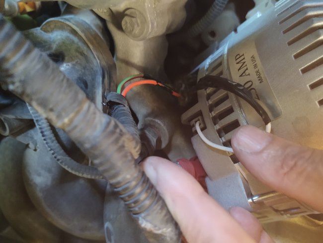
I'm waiting for my access to online service manuals to be fixed. Until then, I can share that the white wire you have your thumb on, (dandy photos, by the way), comes from within the generator and goes right back into it on that three-wire plug. That is mainly a Ford thing going back to the mid '60s. When the charging system is working, that wire taps off part of the output circuitry and will have exactly half of system voltage on it, or roughly 7 volts. That is the voltage that tells the voltage regulator the system is working and for it to turn off the warning light on the dash, when you have that. You can also use that as a test to see if the charging system is working.

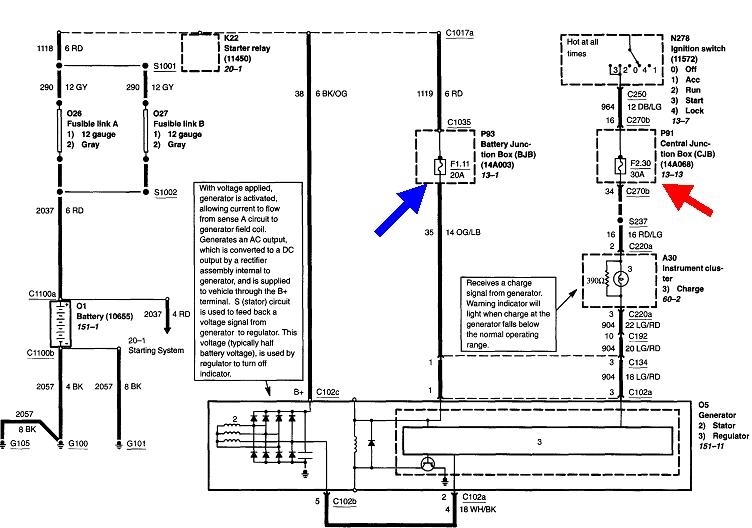
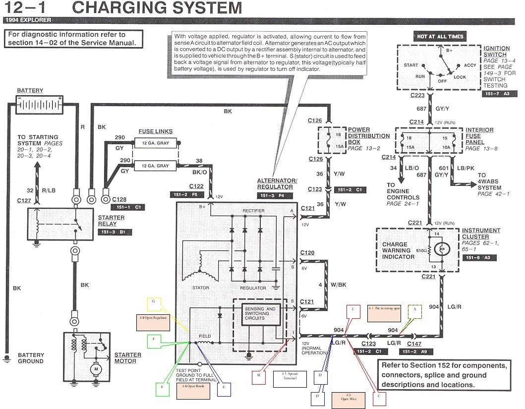
This diagram is for a '94 Explorer, but it should be similar to yours. In later years another unnecessary computer circuit was added to the system. I'll have to wait to see if that applies to your model, but I think this diagram is accurate. Don't pay attention to the callouts I added. Those are for the "bugged" cars I built for my students to diagnose. They show a white / black wire for the white wire you have.

The bottom wire, (shown here as light green / red), is for the dash light. If you see the dash light turn on when the ignition switch is turned on, that circuit is working. It still works if the bulb is burned out as there is a resistor across the bulb for that purpose. Since you have a gauge instead, that circuit is still there, but it just uses that resistor. They show it here as a 510 ohm resistor. Regardless, current flow through that circuit is what tells the voltage regulator to wake up and start doing its thing. At this time you will find very close to 2.0 volts on that green / red wire at the generator, leaving roughly 10 volts to run the bulb, and / or be dropped across the 510 ohm resistor.

Once the regulator sees the charging system is working, (by that 7 volts on the white wire), it puts full system voltage back out on the light green / red wire. With full voltage there, and full voltage on the other side of the bulb from the battery / ignition switch, the difference is 0.0 volts, so the bulb turns off. At this time you will measure full system voltage on the light green / red wire. If you still have around 2.0 volts with the engine running, the charging system is not working properly. In older systems the regulator turned the warning bulb on for a no-charge condition. Beginning around the late '80s or early '90s with this system, the regulator also turns the warning light on for an under-charge and an over-charge condition. In those last two conditions, you'll be able to drive longer, but an over-charge condition can damage the battery.

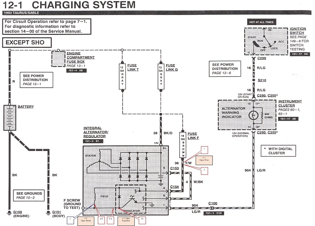
For all of this to work, the system is powered through the yellow / white wire shown at the top of the generator, right side, and it has a tiny "12V" notation under it. That one must have full system voltage at all times. You'll find battery voltage of 12.6 volts with the engine off, and typically 13.75 to 14.75 volts with the engine running. This circuit is the source of a real lot of failure-to-charge problems including after the generator has been replaced. I mentioned earlier that the fuse often blows for no particular reason. I added the second diagram because I noticed in this '94 Taurus, they did away with that fuse in favor of a fuse link wire. Those are a regular wire, but of a smaller diameter making them the weal link in the chain. The insulation is designed to not burn or melt. They take some time to burn open, so they act like a slow-blow fuse. In the 2002 diagram I have on file, they again show a fuse, so now I don't know yet which you have. You didn't find a fuse listed in the under-hood fuse box, and they don't show or list fuse link wires. Regardless, you gotta have 12 volts on that wire. Even if you aren't sure of wire colors or their order in the plug, just measure the voltages on all three with the ignition switch turned off. Two are going to have 0.0 volts and that yellow / white one must have 12.6 volts.

To make this more complicated than necessary, if you don't find that 12 volts on one wire in the plug, unplug it, then carefully measure directly on the terminals. You can't help but insure you're making a good connection with the probe that way. There is one major pitfall to be aware of when doing this. Okay, two things to be aware of. First, don't stuff the probe into a terminal as that can spread it to the point is no longer makes good contact. The more important second point only applies if you have a fuse link wire, not a regular fuse. When fuse link wires burn open, they leave behind a carbon track inside the insulation where arcing occurred. That carbon can conduct enough current for a digital voltmeter to falsely see it as 12.6 volts. That makes it appear the fuse wire is okay. A test light is much more accurate for this type of test because it requires current flow to work, and there's no way any substantial current can get through that carbon track. The test light will correctly show 0 volts.

This is why it is usually only valid when taking voltage readings when it is done with the plug connected. In this case the voltage regulator will be trying to power up from that yellow / white wire, but all of the 12.6 volts will be dropped across the carbon track. That leaves 0 volts to be seen by the voltmeter at the plug.

It occurs to me I overlooked one test. Since you don't have a dash warning light, you don't have that visual indication that circuit is working. Measure the voltage on the light green / red wire. When you have a dash light, the easiest and fastest is to unplug that connector, then test with a test light on all three wires, especially when the colors might be different due to the plug was replaced or my diagram has different colors. You still have that yellow / white wire with 12.6 volts. The white wire is going to have 0 volts. The last one should have a dim test light. Half of the 12.6 volts is dropped across the dash bulb, leaving the other 6 volts to be dropped across the test light's bulb. This assumes you're using a standard test light, not one of the new fancy ones with all kinds of circuitry inside.

This doesn't work when you have only a dash gauge. That's because the 510 ohm resistor is so large, electrically, that it drops almost all of the 12.6 volts leaving nothing to be measured on the light green, red wire. Instead, for this test, leave the plug connected, then back-probe that wire through the back of the plug, with the voltmeter. Expect to see something, but it will be real low. If you aren't sure, now unplug the connector, then read that voltage again. Now you should see the full 12.6 volts.

If the voltage is missing on the light green / red wire, the rest of the system might be okay, but the voltage regulator is not getting the signal to tell it to turn on and start running the generator. Sometimes, due to residual magnetism, the system can self-start on its own, typically when engine speed is raised substantially. As an alternative, you can apply 12 volts to that wire to take the place of the dash circuit. A fast way to do that is to use the test light to act as the dash light. Connect its lead to the battery positive terminal. To verify this works, you're testing for ground now, so it will light up when you touch the probe to the engine block or body sheet metal. Touch the probe to the light green / red wire while the engine is running. You only have to do that for an instant. Once the regulator turns on, it will continue running the generator until the engine stops rotating.
Was this
answer
helpful?
Yes
No
Wednesday, June 30th, 2021 AT 7:45 PM
Tiny
BILL HOOD
  • MEMBER
  • 8 POSTS
The white wire is only shows 0.07 volts and the green and red shows a -0.05 volts.
Was this
answer
helpful?
Yes
No
Friday, July 2nd, 2021 AT 2:18 PM
Tiny
CARADIODOC
  • MECHANIC
  • 33,752 POSTS
White wire indicates the system is not charging. If you have the ignition switch turned on, there's only two ways you can have 0 volts on the green / red wire. It has to be shorted to ground or there's an open circuit, (break in it). Either way the voltage regulator will see the 0 volts that tells it to remain off.

It's real easy to tell if the green / red wire is shorted to ground when you have a dash light. Along with the 0 volts, the dash warning light will be on when the ignition switch is on. There's two places that short can be. It can be within the regulator itself, (not very common), or the wire is grounded, typically where it lays on top of the sharp edge of some bracket. Since you've had multiple generators installed, and shorted regulators aren't very common, we can probably rule that out.

The better suspect is the green / red wire has a break in that circuit. The clue would be the warning light never turns on under any condition. This is where jumping 12 volts to it through the test light would get the system started.

Do that test with the test light. It only takes a couple of seconds. If the green / red wire actually is grounded, the test light will simply be full brightness and the charging system will remain dead. If the green / red wire is open, the test light will be slightly less than full brightness with the engine not running, and it will turn off, just like a dash light would, when the engine is started and the charging system starts operating.

Let me know what happens when you do that test.
Was this
answer
helpful?
Yes
No
Friday, July 2nd, 2021 AT 8:38 PM
Tiny
BILL HOOD
  • MEMBER
  • 8 POSTS
I finally Got it figured out, I really appreciate all your help and I will leave you positive feedback. Thank you!
Was this
answer
helpful?
Yes
No
Wednesday, July 7th, 2021 AT 6:14 PM
Tiny
JACOBANDNICKOLAS
  • MECHANIC
  • 108,269 POSTS
Hi,

I'm glad to hear you got it fixed. What did you find that solved the issues? I'm certain it will help others in the future if you explain.

Thanks,
Joe
Was this
answer
helpful?
Yes
No
Saturday, July 10th, 2021 AT 9:35 PM
Tiny
CARADIODOC
  • MECHANIC
  • 33,752 POSTS
Also happy we could help. I sincerely apologize for being gone so long. I spent the weekend at the Iola Old Car Show. They had free internet access in the past, but not this year. Rats.
Was this
answer
helpful?
Yes
No
Sunday, July 11th, 2021 AT 1:20 PM

Please login or register to post a reply.

Sponsored links