Engine sensors and PCM

Tiny
THUNDERBOLT7777
  • MEMBER
  • 2000 CHRYSLER SEBRING
  • 2.5L
  • 6 CYL
  • 2WD
  • AUTOMATIC
  • 100,000 MILES
I have a voltage at the MAP sensor of 12.5 volts from the PCM as apposed to the 5 volt reference voltage it should be.
Wednesday, April 10th, 2019 AT 1:46 PM

38 Replies

Tiny
CARADIODOC
  • MECHANIC
  • 33,752 POSTS
What's the symptoms. Where are you putting the meter's negative probe?

See what you have on the 5.0-volt feed wire for the throttle position sensor.

Is there a chance you really have an open circuit and you have an auto-ranging voltmeter that's seeing 12.5 millivolts from stray magnetic pick-up? I have over a dozen digital meters I used for tv / vcr repair, and I never had one with auto-ranging because I got tricked too many times when I failed to notice it had switched to a different scale.
Was this
answer
helpful?
Yes
No
+1
Wednesday, April 10th, 2019 AT 2:08 PM
Tiny
THUNDERBOLT7777
  • MEMBER
  • 22 POSTS
Full explanation; My volt meter is grounded right to battery and positive probe is contacted right to the wiring harness to the purple wire with white stripe through it (5 volt reference wire). I might add that in the same way grounded to the battery, using the red probe on the green wire with red stripe (signal wire) I am getting a 1.1 to 1.5 volt reading. This is with key on engine off.
The next test is with harness connected and engine running.
I am getting 12.5 volts through the purple white wire but now get 12.5 volts out of the green red instead of the 1.1 to 1.5.
I just got the car and new it had a gremlin but couldn't pass it up. : ) I am assuming that the PCM has a cooked resistor but want to listen to anything I might be able to do before digging deeper into wiring.
Was this
answer
helpful?
Yes
No
Wednesday, April 10th, 2019 AT 2:21 PM
Tiny
THUNDERBOLT7777
  • MEMBER
  • 22 POSTS
This is a regular volt meter with settings to check DC or AC current ohms as well and the car misses after it warms up through out the driving range but worse at a idle. The volt meter I have reads accurately on anything else I have tested with it.
Was this
answer
helpful?
Yes
No
Wednesday, April 10th, 2019 AT 2:25 PM
Tiny
CARADIODOC
  • MECHANIC
  • 33,752 POSTS
Check the voltage on the TPS. That's fed from the same 5.0-volt source that feeds the MAP sensor.
Was this
answer
helpful?
Yes
No
+2
Wednesday, April 10th, 2019 AT 3:48 PM
Tiny
THUNDERBOLT7777
  • MEMBER
  • 22 POSTS
The TPS voltage is as follows with the harness disconnected and key on and engine of:

1. Signal wire (orange with black or blue stripe?) Has a voltage of 2.5 volts the ground used was direct to the - battery post.
2. The 5 volt reference wire (purple white line) has 12.5 volts the ground used was again directly to the battery post.
3. The ground wire when connected is giving proper ground. This was determined by connecting black lead of the volt meter to the ground wire on TPS 9 black with blue stripe and the red wire to the battery 12 volt supply it red 12.5 volts.
Was this
answer
helpful?
Yes
No
Wednesday, April 10th, 2019 AT 5:11 PM
Tiny
THUNDERBOLT7777
  • MEMBER
  • 22 POSTS
Oh, by the way thanks for the wiring diagrams. I bought a Haynes manual but it doesn't have the emissions wiring in it. The ones you sent are going to help greatly. I guess it is tear down the wiring and make sure there is no damage or shorting before replacing the PCM? Like I stated earlier I just bought the car and it was this way when I got it last fall, it is a convertible so I stored it for the winter and didn't run it. Any other thoughts would be greatly appreciated. Other then that I am all over this like a fat cop on a free donut. : )
Was this
answer
helpful?
Yes
No
+2
Wednesday, April 10th, 2019 AT 10:48 PM
Tiny
THUNDERBOLT7777
  • MEMBER
  • 22 POSTS
Oh, one other thing. On the MAP sensor test the 12.5 volts on the send voltage to the PCM did drop with acceleration but only to about 7.5 - 8.5 approximately.
Was this
answer
helpful?
Yes
No
Wednesday, April 10th, 2019 AT 11:07 PM
Tiny
CARADIODOC
  • MECHANIC
  • 33,752 POSTS
To avoid potential confusion on my part, leave the voltmeter's negative probe on the battery's negative post for all the tests. The only way sensor readings can be accurate is when they're taken with the plugs connected, by back-probing through the rubber weather-pack seals. When unplugged, the Engine Computer is designed to place 5.0 volts on the signal wire to force a defective condition to be detected, and set a fault code.

Now take the three readings at the TPS. You should find 0.2 volts on the ground wire, 5.0 volts on the feed wire, and at idle, roughly 0.5 to maybe 0.7 volts on the signal wire. That one should increase smoothly to around 3.8 to 4.2 volts at wide-open-throttle.

Something has to be wrong with the way you're finding these numbers. The computer will not recognize sensor readings outside of 0.5 to 4.5 volts. Lower and higher signal voltages are what sets diagnostic fault codes. I also find it had to believe the engine would run with multiple out-of-range sensor readings.

By the way, have you read the diagnostic fault codes? Chrysler made that real easy to do yourself. Cycle the ignition switch from "off" to "run" three times within five seconds without cranking the engine, leave it in "run", then watch the code numbers show up in the odometer display. If you don't have all kinds of codes related to the sensors, we'll have to figure out where that 12 volts is coming from.
Was this
answer
helpful?
Yes
No
Thursday, April 11th, 2019 AT 6:24 PM
Tiny
THUNDERBOLT7777
  • MEMBER
  • 22 POSTS
Hi, this car wont give me the fault codes through the key method, I have a scanner that gave me a P0108 code (MAP sensor high voltage), then I cleared that and reran the vehicle till it gave another code P0123 (TPS High voltage). I wish there was a way to explain it as I find it pretty strange it is running giving that kind of voltage in and out of the PCM and sensors? I have used my volt meter straight to the battery and it gives me the 12 volt reading so the meter isn't giving false readings . I have a question, Could it be possible that before I got the car a new or different PCM was put into it and they never got it programmed? Would this cause the car to act like it is? I have a friend that has a used parts yard so I got a used PCM (made sure the one I borrowed had the same numbers on it as mine) and switched them out today just to see and my car acted the exact same so I know the one I borrowed couldn't have been programmed for my engine? Would this cause it to act the way it is?
The car runs fine when it is cold but as soon as it warms up it starts to miss intermittently and it is using a phenomenal amount of gas. I also notice that the tachometer shows differently at different speeds. Ie at 100 kphs it will register 2400 sometimes and 2000 other times.I would suspect the EGR system given that it runs good when its cold but other then I do know the diaphragm does leak ever so slightly (being replaced on payday) the solenoid works fine, it has back pressure and the plunger works. The voltage readings im getting are pointing else where though?
Was this
answer
helpful?
Yes
No
Thursday, April 11th, 2019 AT 7:22 PM
Tiny
CARADIODOC
  • MECHANIC
  • 33,752 POSTS
As far as I know, that computer shouldn't need to be programmed, but there is something much more important to be aware of. I know this applies to '92 Dynastys, '94 Intrepids, and '99 Neons. You should be aware of this too.

If your car came with factory-installed optional anti-theft system, you can use any Engine Computer for your application. Don't worry about part numbers. They change every time one is sent back for repair or updates. You're more likely to get one with a different number, or an "AB" or "AC" at the end instead of an "AA". The problem is once the computer has been plugged into your car and the ignition switch turned on, that computer can only be used in another car with anti-theft system.

The factory anti-theft system lives in the Engine Computer and the Body Computer. When you buy a rebuilt computer through the dealer, they always come without the anti-theft programming. In the case of the Engine Computer, as soon as you turn on the ignition switch, it learns that programming from the Body Computer, and the engine starts like normal. If you put that new computer in a car that doesn't have anti-theft, it never learns that programming and it never needs the "disarm" signal to let the engine run. That disarm signal is never coming.

The problem is that anti-theft programming can not be undone. Once it has been learned, it will only let the engine run when the signal tells it is okay to do so. This is where borrowing a computer can get you in trouble. The first scenario is neither your car or the donor car has anti-theft. Either Engine Computer and either Body Computer will work in either car.

If both cars have anti-theft, again all four computers will work in either car, but none of them must be used in some other car that doesn't have anti-theft.

If the donor car doesn't have anti-theft but yours does, you can put either used computer into your car, and it will learn the programming, but if you put the used one back into the donor car, it is going to teach that programming to the other computer. At that point, the donor engine will not start until both computers are replaced.

The worse one is when the donor car has anti-theft but your car doesn't. When you plug in the used Engine Computer, it will immediately teach the programming to your Body Computer. Now you have a crank / no-start because there's nothing to provide the disarm signal. The only way to get your engine running now is to replace both computers with ones without anti-theft programming.

The problem is we rarely know what programming was in a salvage yard computer, so you're taking a big risk with one if your car doesn't have it. You could end up ordering two new computers.

Before you go through this risk, a better approach would be to isolate the 5.0-volt feed wire to try to determine where it's getting 12 volts from. Voltage is only supposed to be on that circuit when the ignition switch is on. If the 12 volts is coming from an adjacent wire in the harness being shorted together, that could be a 12-volt source that's there all the time, or only when the ignition switch is on. Turn the ignition switch off, then see what you have on the MAP and TPS for the feed circuit. It should be 0 volts. If you find 12 volts now, unplug the Engine Computer to verify it's still there. Now you have something to search for.

Unplug the two-wire coolant temperature sensor and measure the voltages on them. When it's unplugged, one of them should read 5.0 volts. That comes from the same regulated source inside the Engine Computer, but it comes out on a different circuit. If there's a problem with that 5.0-volt supply, you should find 12 volts on this wire too. If you find 5.0 volts, it suggests the computer is okay and the 12 volts on the other circuit is coming from some external short.

If the 12 volts only shows up when the ignition switch is on, the 5.0-volt feed wire has to be isolated. That is rather tedious to remove one terminal from the connector, and some connector designs are a real lesson in frustration to try to put back together. I hate to do this, but you might need to cut that wire, then see which part has the 12 volts on it. If it's coming right out of the computer, I'd be real surprised, but that would be hard to argue with.

Onto the next subject, the fault codes agree with what you've already found. The reason the engine runs as well as it does, is in many instances, when the code shows a sensor's signal voltage can't be trusted or believed, the computer disregards it, then "injects" an approximate value to run on. The MAP signal is the most important one for fuel metering calculations, but the computer can approximate values that are close based on engine speed, transmission gear, and direction of throttle movement. All the engine sensors are involved in some way with the 5.0-volt source, but they may not all set fault codes. To set a fault code there is always a real long list of conditions that must be met, and one of those conditions is that certain other codes can't already be set. When two sensors or operating conditions are compared as part of the test strategy, if the computer detects a problem with one of them and sets a fault code, it knows it can't use that as reference for other things that need it, so it suspends those tests.
Was this
answer
helpful?
Yes
No
+2
Friday, April 12th, 2019 AT 7:12 PM
Tiny
THUNDERBOLT7777
  • MEMBER
  • 22 POSTS
Hi, the donor car has exactly the same options as mine so the computer operated the same as the one that is in my car. It is a no brainer now anyway as the test has been done already and no difference so my computer has been reinstalled with no difference. If I am correct the donor car from the VIN# was made four cars after mine from the same factory in Mexico. At any rate this is a no brainer now and I am assuming its not the PCM ? I opened the PCM and did find small beads of moister on the bed where the harness connects, and yes the 12 volt supply connects there. I have not determined just yet if that is the issue.
I have assumed now that there is only one way 12 volts would get to the 5 volt reference and that may or may not be from the little moister I found or from the harness having a short inside. The 5 volt wire only gives 12 with the key turned on or it has no voltage at all. Would you have a diagram of the PCM wiring harness?
Was this
answer
helpful?
Yes
No
Friday, April 12th, 2019 AT 8:12 PM
Tiny
CARADIODOC
  • MECHANIC
  • 33,752 POSTS
Be careful when looking at the VINs. The only time when a run of cars are identical is when they're making them special for rental agencies or special-ordered fleet vehicles. Other than those, each car is an individual with its own list of optional equipment. The only variable noted in the VIN is the engine size. It might be a good idea to mark on the donor computer whether or not it has the anti-theft programming activated to avoid future frustration.

What I'd do next is unplug the Engine Computer, turn on the ignition switch, then see if the 12 volts is on that line. Moisture inside the computer should not be the cause as it is sealed in a protective jell. I've never heard of a computer causing this problem, and surely not two in a row.

This next suggestion is based on my experience with tv and vcr repair. They use voltage regulator circuits similar to what is in an Engine Computer, and one thing that will cause them to put out the same voltage that's coming in is a broken ground circuit. On most Chrysler computers there will be four ground wires, two called "signal" grounds and two called "power" grounds. What they mean by power grounds is those are the ground wires for things that take a lot of power, like ignition coils, injectors, relays, and solenoids. The second wire is a backup in case there's high resistance on the first one.

Signal grounds refer to very low-current circuits, meaning sensors. These use separate ground wires because if a little resistance develops in a power ground circuit, that can easily be low enough to not cause a problem for those systems, but each time a pulse of current flows through it, that will cause a voltage to be dropped across that resistance. A motor or solenoid won't care, but if as little as a few hundredths of a volt appears there, it will raise the signal voltage on all the sensors by a proportional amount. A few hundredths of a volt means quite a bit to a MAP sensor. To prevent interacting, the two systems get their own ground circuits.

With the computer unplugged, you can try reading the resistance to ground on the four ground wires, but this is not an accurate test for this type of problem. Remember to include the roughly five ohms of resistance in the meter leads themselves. The best you can hope for is to find infinite resistance, (open circuit), on one of the wires. A small resistance that's too small to measure can still be high enough to cause problems. The way to find that is take voltage readings on them when the computer is in operation, meaning engine running. You'll need to back-probe through the connector's rubber weather-pack seals to touch the back of the terminals. Ideally you should find 0.00 volts on every ground wire. In practice, expect to find a little. As bad as this is on your car, if you do find notable voltage on a ground wire, there isn't likely to be any confusion as to whether it's too much.

While you have the plugs off the computer, this is a good time to measure between the 12-volt feed wires and the five-volt sensor wire to see if any are shorted together. It looks like that would be the switched 12 volts, terminal 20, and the five-volt feed, terminal 61, but check to the other 12-volt feeds too. An often-overlooked 12-volt feed is terminal 6. That comes from the ASD relay when it turns on.

If you watch when the 12 volts appears on the five-volt line, it might provide a clue too. You'll have to watch the meter closely because most digital meters take a while to respond. You found the 12 volts is not there when the ignition switch is off. If it appears the instant you turn the ignition switch to "run", and stays there solid, it's coming from a source that stays on with the engine off. If you see it go to 12 volts for one second, then drop to five volts or 0 volts until the engine is cranking, it's coming from the 12-volt line leaving the ASD relay.
Was this
answer
helpful?
Yes
No
+1
Saturday, April 13th, 2019 AT 9:15 PM
Tiny
THUNDERBOLT7777
  • MEMBER
  • 22 POSTS
Hi, how are you? I think I found the problem. I cut the violet/white wire 5 volt near the computer and measured it coming out of the computer with the key on it gave a 12 volt reading. So the computer I can assume is not reducing the volts to the 5 volt but sending 12 volts to the sensors. I assume there is no other reason that this can be? I also am hoping that there isn't a short in the wiring somewhere that would cause this as if there is putting a new computer in it will end up the same way?
Was this
answer
helpful?
Yes
No
+1
Tuesday, April 16th, 2019 AT 12:56 PM
Tiny
CARADIODOC
  • MECHANIC
  • 33,752 POSTS
Very interesting! The computer shuts the 5.0-volt supply down to protect it when something on that line is shorted to ground. Once the short is removed, you only need to turn the ignition switch off, then back on to reset it and get the 5.0 volts back.

I mentioned that a broken ground circuit will make a voltage regulator circuit unable to do its job, but in cars, I'm pretty sure there will be other, more serious issues. I've never seen a computer do this, but to satisfy my curiosity, unplug the two-wire coolant temperature sensor and measure the voltage on those wires. The ground wire should have 0.2 volts. The other one should be 5.0 volts when it's unplugged.

Now that the violet wire is cut, see what is on the other part you cut off. That should be 0 volts now, but you might find something on there back-feeding through other sensors on that circuit. I doubt you're going to find 12 volts there, but if you do, we'll want to figure out if that is coming through the other sensors or if it is coming from the 5.0-volt wire being shorted to a 12-volt wire. Even if a short puts 12 volts on the 5.0-volt line, that shouldn't damage the computer.
Was this
answer
helpful?
Yes
No
Tuesday, April 16th, 2019 AT 8:14 PM
Tiny
THUNDERBOLT7777
  • MEMBER
  • 22 POSTS
Hi, okay I tested the coolant temperature sensor and it gave a 8.2 volt reading on the orange/black wire and I am using a volt meter not digital so doesn't have the capability to measure 0.2 volts, but the needle did move ever so slightly when hooked to the black/blue ground wire.
The other side of the 5 volt violet/white wire from the PCM that was cut has no voltage. I want to thank you for all your help in this situation. : )
Was this
answer
helpful?
Yes
No
Wednesday, April 17th, 2019 AT 11:18 AM
Tiny
CARADIODOC
  • MECHANIC
  • 33,752 POSTS
I have to admit, it looks like the internal 5.0-volt regulator circuit is shorted. Darn the bad luck!
Was this
answer
helpful?
Yes
No
Wednesday, April 17th, 2019 AT 2:25 PM
Tiny
THUNDERBOLT7777
  • MEMBER
  • 22 POSTS
Hi, so how does that occur?
Was this
answer
helpful?
Yes
No
Wednesday, April 17th, 2019 AT 2:56 PM
Tiny
CARADIODOC
  • MECHANIC
  • 33,752 POSTS
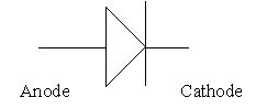
First, start with a simple diode. That's a one-way valve for electrical current flow. There's always at least six really beefy diodes in an alternator. Alternators produce alternating current. The diodes redirect the multiple currents to all go in one direction, producing direct current that can be stored in a battery. In electronic circuitry, diodes are usually very small, as in the diameter of a pencil lead, and most commonly, less than 1/4" long. Even at that tiny size, they're that big to provide surface area for heat dissipation. While they block current flow one way, an important point about diodes is it takes 0.6 volts in the "forward-biased" direction before current starts to flow that way.

There's two theories about the direction current flows in a wire. Technically, electrons come out the negative post of the battery when that battery is powering something, but for ease of understanding, we use the other theory where current leaves the positive post. With this theory, the triangle part of a diode symbol points in the direction current can flow. In the first drawing, once the voltage is 0.6 volts higher on the anode than on the cathode, current will flow from left to right.

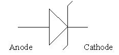
Next, there's a special kind of diode called a "zener" diode that almost always finds a place in regulator circuits. Its symbol has two little wings added to it as in the second drawing. In the forward direction, it acts like any other diode, but in the reverse direction, it blocks current flow until a very specific voltage is reached, then it lets current flow from right to left, but it maintains that "zener voltage". Compare this to a dam on a river. No water flows over that dam until it gets as high as the dam, then it spills over and the water behind the dam can't get any higher. The zener voltage is designed in, and we choose the correct value for the needs of the circuit. The zener voltage can be anywhere from a few volts to hundreds of volts.

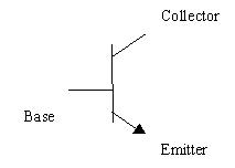
The third drawing shows the most common of many types of transistors. This is in effect, two diodes connected back to back, in this case, anode to anode. The leg with the arrow, (emitter), is the same as the diode symbol and shows which way current can flow. The neat thing about transistors is they can amplify current. How much they do that is called its "beta", or "Hfe". This is a design value that we choose to meet the needs of the circuit. Beta can range from a low of less than 10 for high-power applications such as audio amplifiers, to well over 10,000 for specialized applications. For this sad story, a typical value is 100.

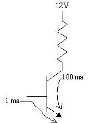
The fourth drawing shows current flow through a transistor with a beta of 100. If one milliamp flows from the base to the emitter, it will cause 100 milliamps to flow from the collector to the emitter. As a side note, where this becomes valuable in an audio circuit is when current flows through the resistor, then through the collector, some voltage is dropped across that resistor. That means we'll see less than 12 volts at the collector. Instead of one milliamp through the base, if that was a small varying audio signal, it would result in a large varying voltage at the collector. This is just one stage of many in a home audio amp.

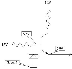
The transistor has a different purpose in a regulator circuit. Instead of amplifying current, which it still does, we're using if for that 0.6 volts less it takes on the emitter to get current to flow through that junction. In the fifth drawing, the zener diode is a 5.6 volt zener, and it is going to hold the voltage on the base of the transistor very solid. Exactly 0.6 volts less will appear on the emitter, and that is the 5.0 volts that feeds the sensors and a lot of other circuitry inside the computer.

Now for the failure you asked about. Any time there's current flow, there's heat build-up, and heat is the deadly enemy of transistors and diodes. The most common failure would be the transistor shorts between the collector and emitter. Basically the three-part silicon crystal melts into one big blob that acts like a piece of wire. Since the sensor circuits draw very little current which is coming through the top resistor, very little voltage is dropped across it, so most of the 12 volts remains and is seen at the emitter and sensors.

A different failure might be the zener diode opens, meaning it's like it isn't in the circuit. The 12 volts coming in from the left resistor is supposed to be drawn down to 5.6 volts by the diode, but with it open, the full 12 volts will be seen on the base, then you'll find 11.4 volts on the emitter.

Those are just two examples of common failures. Often you'll find another zener diode from the emitter to ground, and that one will have a high enough zener voltage to never conduct current except during this type of failure. It might be a 6.0-volt zener that would limit how high the voltage could rise to if the regulator fails.

Another method is to use a similar regulator before this one that regulates the voltage to, ... Say, ...8.0 volts. If that first stage shorted, the second one would still do the job of regulating the 5.0 volts, but it would be under more stress. If the second stage shorted, the output voltage could only go to 7.4 volts, which wouldn't be acceptable, but it wouldn't be quite so bad. The disadvantage with multiple stages is you have multiple chances for a transistor to become open, then you'd have 0 volts instead of five volts.
Was this
answer
helpful?
Yes
No
+1
Wednesday, April 17th, 2019 AT 5:39 PM
Tiny
CARADIODOC
  • MECHANIC
  • 33,752 POSTS
Now that I shared all that wondrous information, the entire circuit can be simplified by using a "three-terminal regulator" as shown below. Physically, these look exactly the same as a common power transistor, about 1/2" tall and 3/8" wide, with a screw mounting hole so it can be bolted to an aluminum heat sink. The difference here is you buy one made for the voltage you want, 5.0 volt and 8.0 volt being the most common, but there are very many more available, and you don't have to worry about all the other resistors, diodes, and connections between them. That is all built into the part, so you literally need to connect the middle lead to ground, and the input lead to any voltage higher than what will be coming out. These are very stable and rugged, but often they're used in place of the zener diode as a sort of pre-regulator stage.

These are also available in a smaller version, just smaller than a pencil eraser. The larger they are, the more current they're designed to handle. These don't fail often, but when they do, it seems it's more common for them to go open, resulting in 0 volts output. I never played with one to see what would happen if the ground leg was open. I assume the output voltage would go to 0 volts since its internal circuitry wouldn't turn on to do anything, but I suppose it's possible the output voltage could rise to near the input voltage.
Was this
answer
helpful?
Yes
No
Wednesday, April 17th, 2019 AT 5:59 PM
Tiny
THUNDERBOLT7777
  • MEMBER
  • 22 POSTS
Neat where would I get one of these? It would be real easy to just hook it to the 5 volt ref line and leave the same line disconnected from the computer.
Was this
answer
helpful?
Yes
No
Wednesday, April 17th, 2019 AT 6:47 PM

Please login or register to post a reply.

Sponsored links