Okay, the 128 is a stuck open thermostat and must be replaced.
https://www.2carpros.com/articles/replace-thermostat
The 219 is a fuel trim code. This has nothing to do with the temperature issue.
I attached the possibilities for you and the flow chart below.
Roy
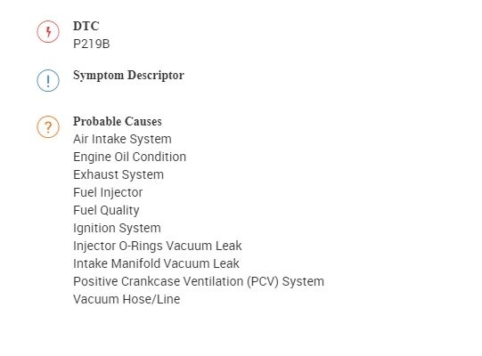
DTC P219A or P219B
Diagnostic Instructions
Perform the Diagnostic System Check - Vehicle (See: Vehicle > Initial Inspection and Diagnostic Overview > Diagnostic System Check - Vehicle) prior to using this diagnostic procedure.
Review Strategy Based Diagnosis (See: Vehicle > Initial Inspection and Diagnostic Overview > Strategy Based Diagnosis) for an overview of the diagnostic approach.
Diagnostic Procedure Instructions (See: Vehicle > Initial Inspection and Diagnostic Overview > Diagnostic Procedure Instructions)provides an overview of each diagnostic category.
DTC Descriptors
DTC P219A
Fuel Trim Cylinder Balance Bank 1
DTC P219B
Fuel Trim Cylinder Balance Bank 2
Circuit/System Description
The Fuel Trim Cylinder Balance diagnostic detects a rich or lean cylinder to cylinder air/fuel ratio imbalance in each bank. The diagnostic monitors the pre-catalyst heated oxygen sensor (HO2S) signal's frequency and amplitude characteristics by calculating an accumulated voltage over a predetermined sample period. An imbalance is indicated when multiple samples of the accumulated voltage are consistently higher than the desired value.
Conditions for Running the DTC
DTCs P0030, P0050, P0053, P0059, P0101, P0102, P0103, P0106, P0107, P0108, P0116, P0117, P0118, P0128, P0131, P0132, P0133, P0134, P0135, P0151, P0152, P0153, P0154, P0155, P0201-P0206, P0300, P0301-P0306, P0442, P0443, P0446, P0449, P0452, P0453, P0455, P0496, P0606, P0641, P0651, P1133, P1153, P1516, P2101, P2120, P2122, P2123, P2125, P2127, P2128, P2135, P2138, P2176 are not set.
The device control is not active.
The intrusive diagnostics are not active.
The engine overspeed protection is not active.
The power take-off (PTO) is not active.
The traction control is not active.
The engine is in Closed Loop status.
The system voltage is between 10-32 V for greater than 4 s.
The engine run time is greater than 125 s.
The engine coolant temperature (ECT) is warmer than -20°C (-4°F).
The engine speed is between 425-6,000 RPM.
The mass air flow is between 20-510 g/s.
These DTCs run continuously when the above conditions have been met.
Conditions for Setting the DTC
Multiple samples of the pre-catalyst HO2S accumulated voltage are consistently greater than the desired value.
Action Taken When the DTC Sets
DTCs P219A and P219B are Type B DTCs.
Conditions for Clearing the MIL/DTC
DTCs P219A and P219B are Type B DTCs.
Diagnostic Aids
The fuel trim cylinder balance diagnostic is very sensitive to heated oxygen sensor (HO2S) design. A non-OE sensor or an incorrect part number may cause a DTC to set.
Monitoring the misfire current counters, or misfire graph, may help to isolate the cylinder that is causing the condition.
Certain aftermarket air filters may cause a DTC to set.
Certain aftermarket air induction systems or modifications to the air induction system may cause a DTC to set.
Certain aftermarket exhaust system components may cause a DTC to set.
Reference Information
Schematic Reference
Engine Controls Schematics (See: Powertrain Management > Electrical > Engine Controls Schematics)
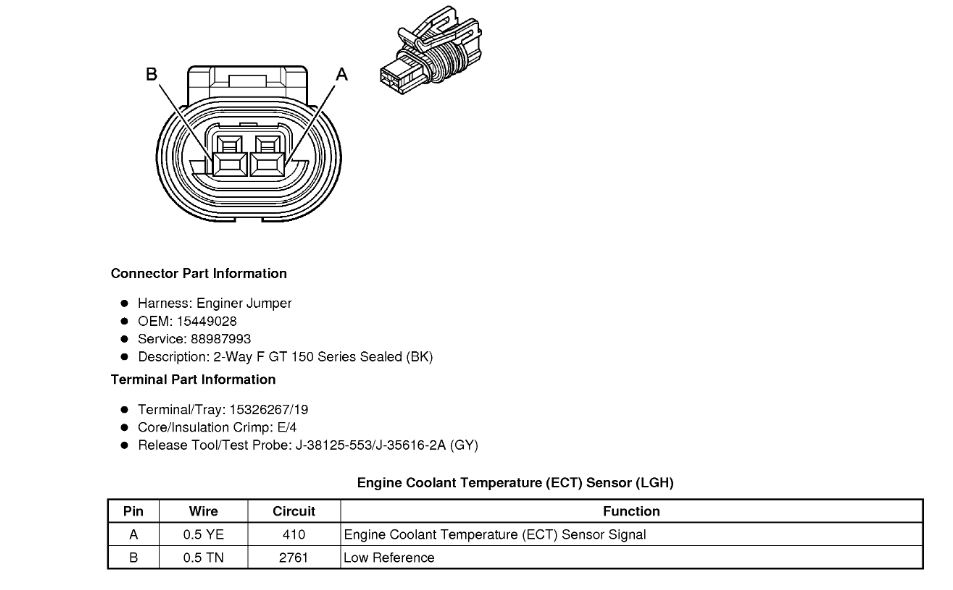
Connector End View Reference
Component Connector End Views (See: Vehicle > Connector Views > Connector End Views By Name)
Electrical Information Reference
Circuit Testing (See: Vehicle > Component Tests and General Diagnostics > Circuit Testing)
Troubleshooting with a Test Lamp (See: Vehicle > Component Tests and General Diagnostics > Troubleshooting With a Test Lamp)
Testing for Intermittent Conditions and Poor Connections (See: Vehicle > Component Tests and General Diagnostics > Testing for Intermittent Conditions and Poor Connections)
Wiring Repairs (See: Vehicle > Component Tests and General Diagnostics > Wiring Repairs)
DTC Type Reference
Powertrain Diagnostic Trouble Code (DTC) Type Definitions (See: A L L Diagnostic Trouble Codes ( DTC ) > Diagnostic Trouble Code Descriptions > Powertrain Diagnostic Trouble Code (DTC) Type Definitions)
Scan Tool Reference
Control Module References (See: Vehicle > Programming and Relearning)for scan tool information
Circuit/System Testing
1. Read and record the Freeze Frame/Failure Records data taking note of the speed and load at which the DTC set.
2. Diagnose any other DTCs that are set. Refer to Diagnostic Trouble Code (DTC) List - Vehicle (See: A L L Diagnostic Trouble Codes ( DTC ) > Diagnostic Trouble Code Descriptions > Diagnostic Trouble Code (DTC) List - Vehicle).
3. With the engine idling and the transmission in the Park or Neutral position, observe the manifold absolute pressure (MAP) sensor parameter. The MAP sensor parameter should be between 19-42 kPa.
If the MAP sensor parameter is not between 19-42 kPa, refer to DTC P0106 (See: A L L Diagnostic Trouble Codes ( DTC ) > P Code Charts > Powertrain Management) or DTC P0107 or P0108 (See: A L L Diagnostic Trouble Codes ( DTC ) > P Code Charts > Powertrain Management).
4. Inspect the air induction system for modified, damaged, leaking, or restricted components.
5. Inspect the crankcase ventilation system for improper operation.
6. Inspect the vacuum hoses for splits, kinks, and improper connections.
7. Inspect for vacuum leaks at the intake manifold, the throttle body, and the injector O-rings.
8. Test for a restricted, damaged, leaking, or modified exhaust system from the catalytic converter forward. Refer to Symptoms - Engine Exhaust (See: Exhaust System > Symptom Related Diagnostic Procedures > Symptoms - Engine Exhaust).
9. Test the fuel injectors for improper operation. Refer to Fuel Injector Diagnosis See: Computers and Control Systems > Component Tests and General Diagnostics > Fuel Injector Diagnosis.
10. Test for fuel contamination. Refer to Alcohol/Contaminants-in-Fuel Diagnosis See: Computers and Control Systems > Component Tests and General Diagnostics > Alcohol/Contaminants-In-Fuel Diagnosis.
11. Test for excessive fuel in the crankcase due to leaking injectors.
12. Test the ignition system for improper operation. Refer to Electronic Ignition System Diagnosis (See: Computers and Control Systems > Component Tests and General Diagnostics > Electronic Ignition System Diagnosis).
13. Test the engine for any mechanical conditions such as sticking valves, lifters, etc., which could alter the flow into the combustion chamber. Refer to Symptoms - Engine Mechanical (See: Engine > Symptom Related Diagnostic Procedures > Symptoms - Engine Mechanical).
Repair Instructions
Perform the Diagnostic Repair Verification (See: A L L Diagnostic Trouble Codes ( DTC ) > Verification Tests > Diagnostic Repair Verification) after completing the diagnostic procedure. Verify the repair under the same speed and load as noted in the Freeze Frame/Failure Records data recorded during testing.
May 5, 2020 at 10:40 AM