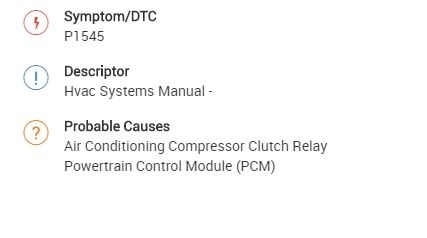
Here is the information on the 1545.
Roy
DTC P1545
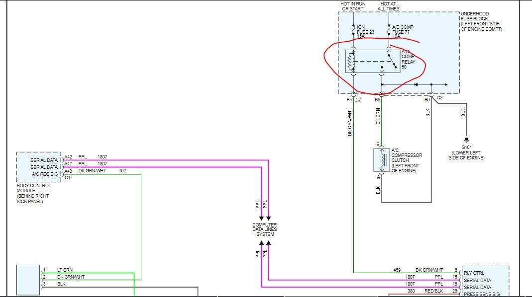
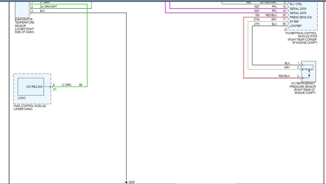
CIRCUIT DESCRIPTION
Ignition voltage is supplied directly to the A/C compressor clutch relay. The powertrain control module (PCM) controls the relay by grounding the control circuit through an internal solid state device called a driver. The primary function of the driver is to supply the ground for the component being controlled. Each driver has a fault line which is monitored by the PCM. When the PCM is commanding a component ON, the voltage of the control circuit should be near 0 volts. When the PCM is commanding the control circuit to a component OFF, the voltage potential of the circuit should be near battery voltage.
DTC DESCRIPTOR
This diagnostic procedure supports the following DTC:
DTC P1545 Air Conditioning (A/C) Clutch Relay Control Circuit.
CONDITIONS FOR RUNNING THE DTC
The ignition voltage is between 9-18 volts.
The PCM driver is activated for at least 0.5 second.
CONDITIONS FOR SETTING THE DTC
The PCM detects an improper voltage level on the output circuit that controls the A/C relay.
ACTION TAKEN WHEN THE DTC SETS
The PCM will not illuminate the malfunction indicator lamp (MIL).
The PCM stores the failure records.
The A/C compressor clutch is disabled.
CONDITIONS FOR CLEARING THE DTC
The diagnostic trouble code (DTC) will become history if the PCM no longer detects a failure.
The history DTC will clear after 40 consecutive warm-up cycles have occurred without a malfunction.
The DTC can be cleared with a scan tool.
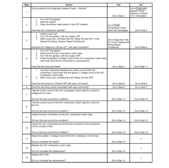
TEST DESCRIPTION
Steps 1 - 13
imageOpen In New TabZoom/Print
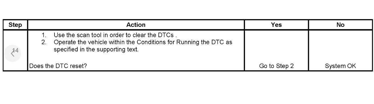
Step 14
imageOpen In New TabZoom/Print
The numbers below refer to the step numbers on the diagnostic table.
3. Listen for an audible click when the A/C compressor clutch relay operates. Command both the ON and OFF states. Repeat the commands as necessary.
4. This step tests for voltage at the coil side of the A/C compressor clutch relay. A 15-amp fuse supplies power to the coil side of the A/C compressor clutch relay.
5. This step verifies that the PCM is providing ground to the A/C compressor clutch relay.
6. This step tests if ground is constantly being applied to the A/C compressor clutch relay.
13. Perform the programming procedure for the PCM.
Images (Click to enlarge)
Jan 15, 2020 at 6:54 AM