Hi,
I will provide the directions for the removal and installation of the dashboard assembly. It is extensive. The attached pics correlate with the directions.
____________________________________________
1998 Ford Truck Expedition 4WD V8-5.4L SOHC VIN L
Removal
Vehicle Body and Frame Interior Moulding / Trim Dashboard / Instrument Panel Service and Repair Procedures Instrument Panel - Replacement Removal
REMOVAL
REMOVAL
pic 1
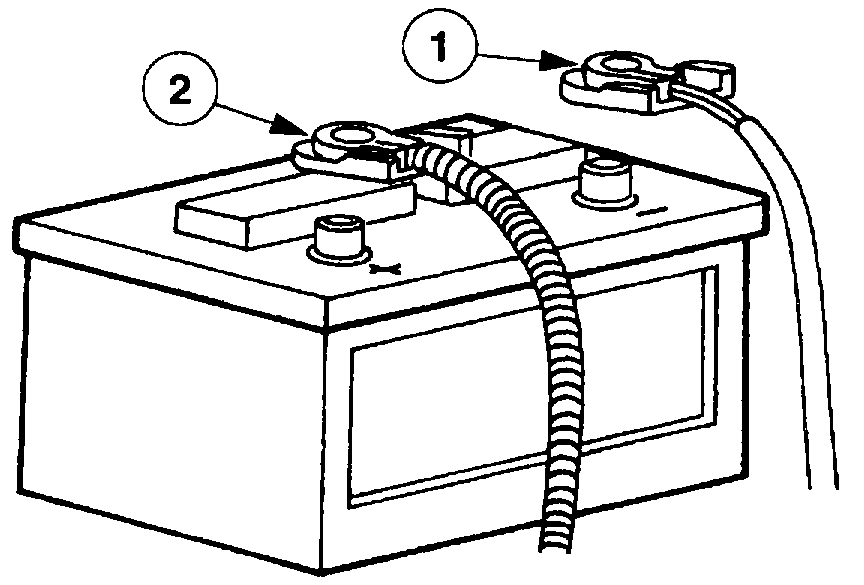
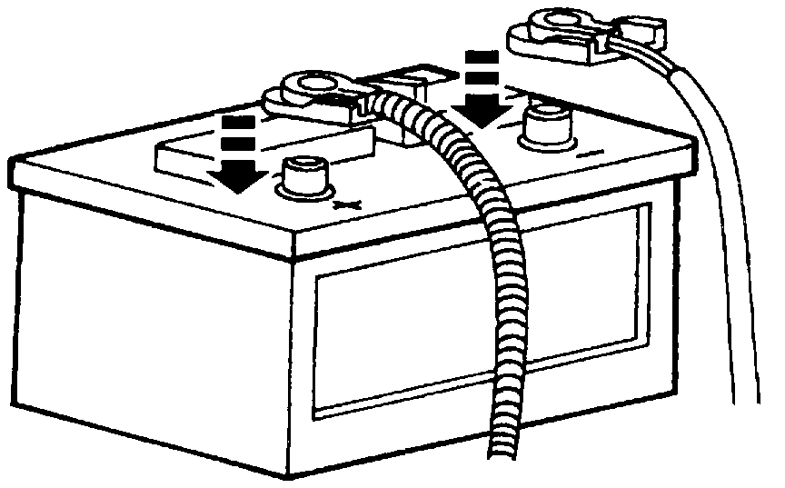
1. Disconnect the battery cables.
1 Disconnect the battery ground cable.
2 Disconnect the battery to starter relay cable and wait one minute for the backup power supply to be depleted.
Warning: to avoid accidental deployment and possible injury, the backup power supply must be depleted before repairing or replacing any air bag system components. To deplete the backup power supply energy, disconnect the battery to starter relay cable and wait one minute.
2. If equipped, remove the front floor console assembly.
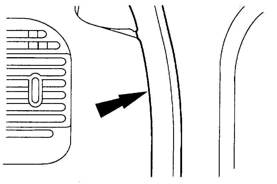
3. Remove the instrument panel steering column cover.
Pic 2
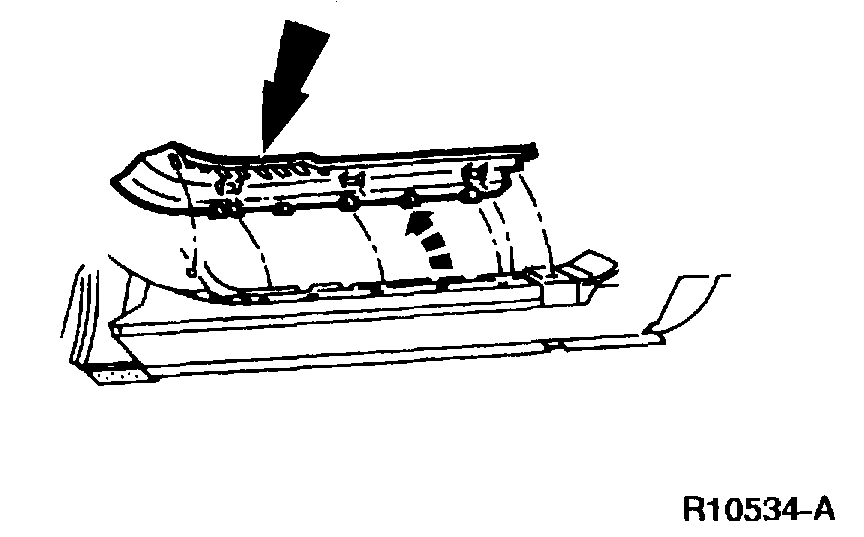
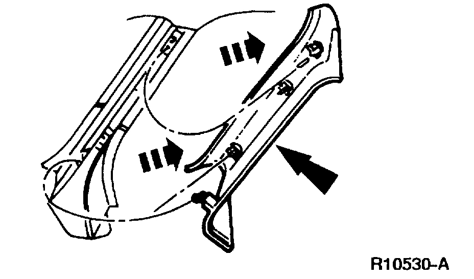
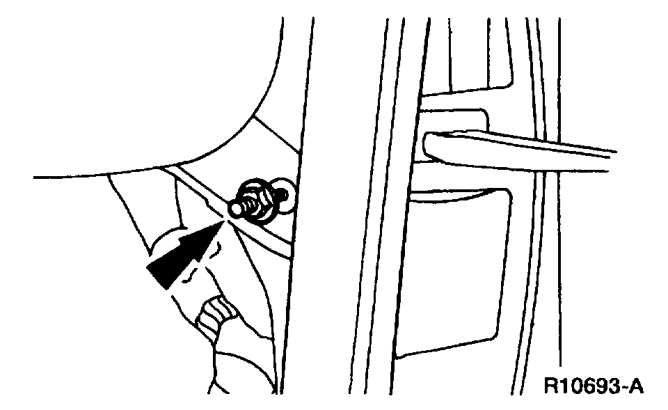
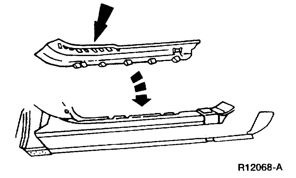
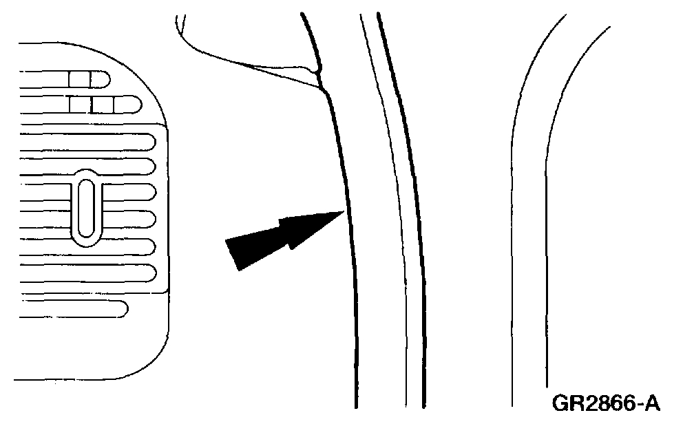
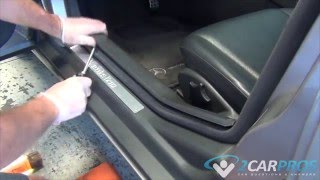
4. Remove the LH and RH scuff plates.
Pic 3
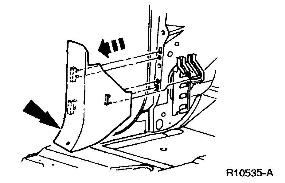
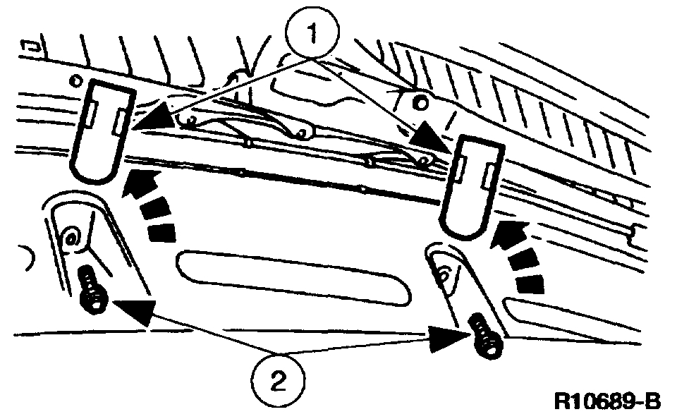
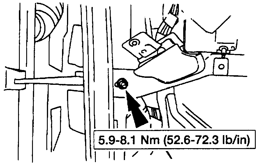
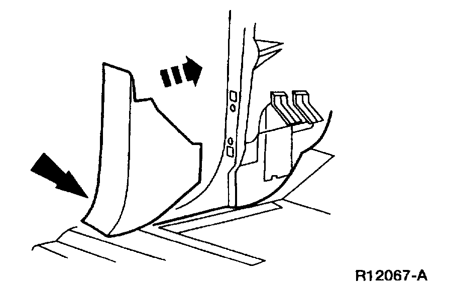
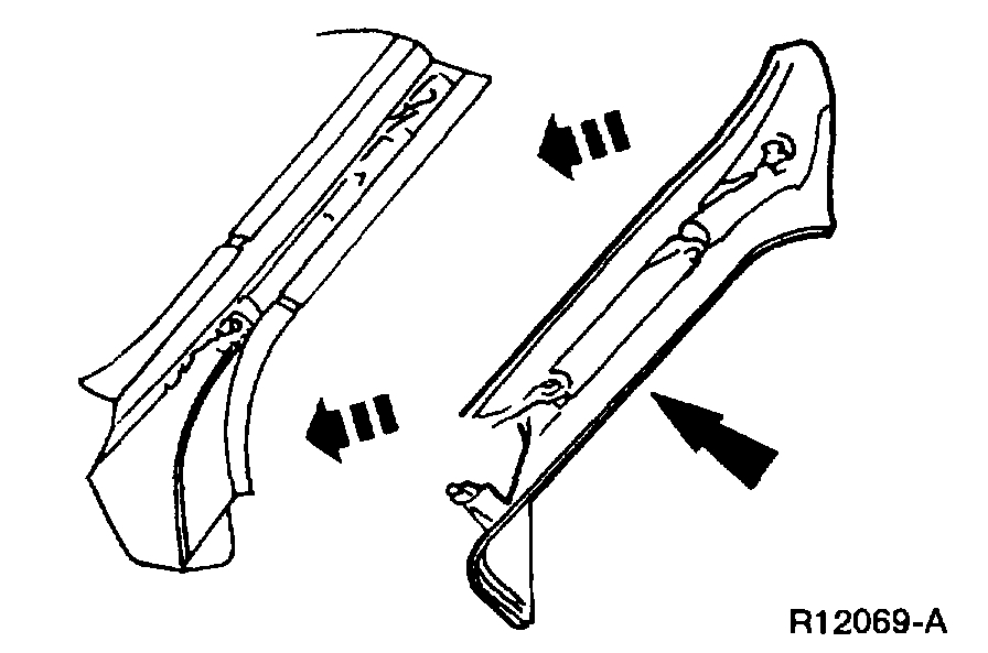
5. Remove the LH and RH cowl side trim panels.
Pic 4
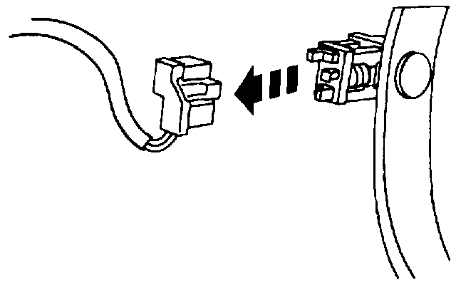
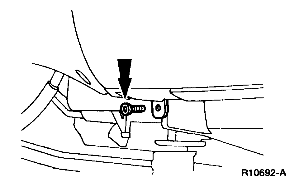
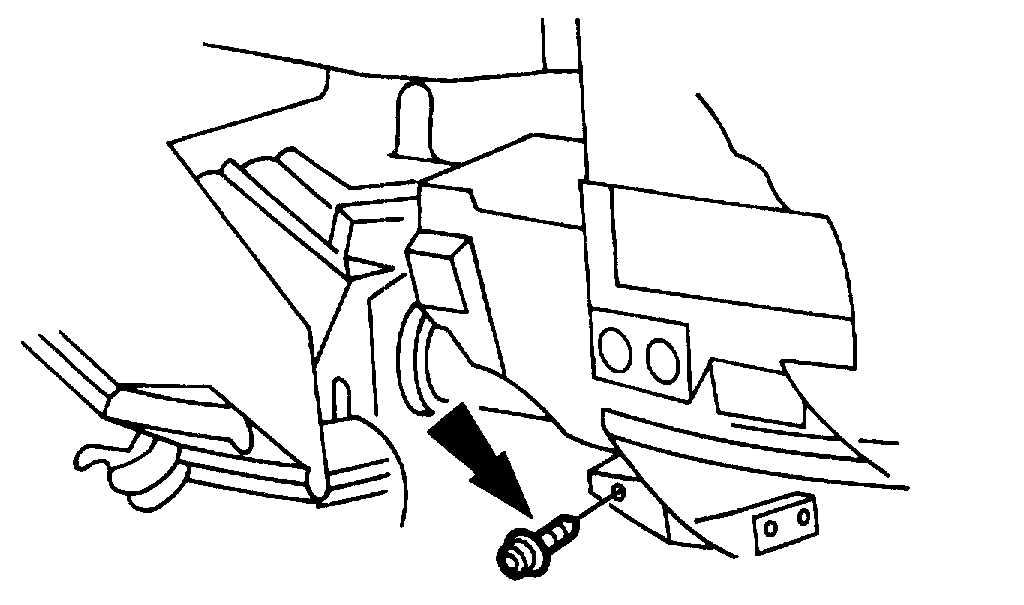
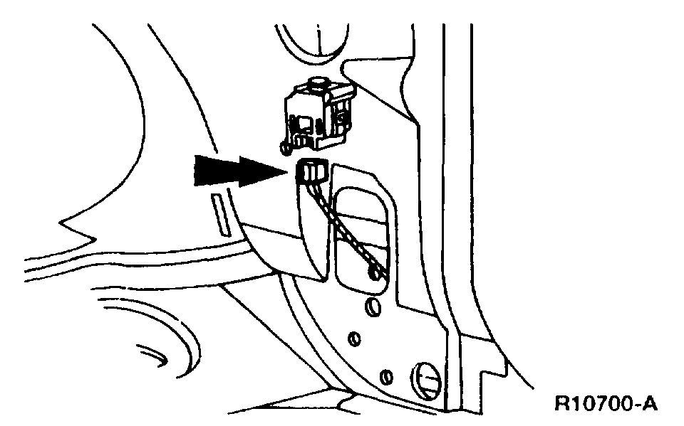
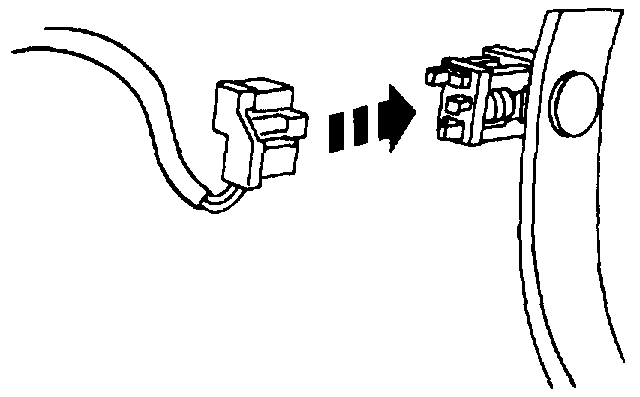
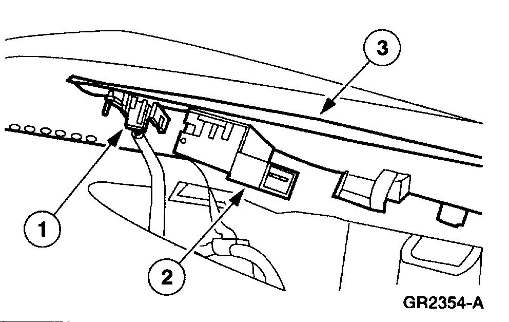
6. Disconnect the Brake Pedal Position (BPP) switch electrical connector.
Pic 5
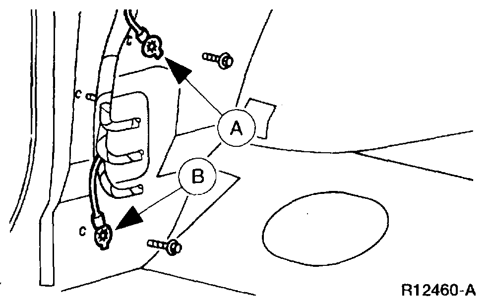
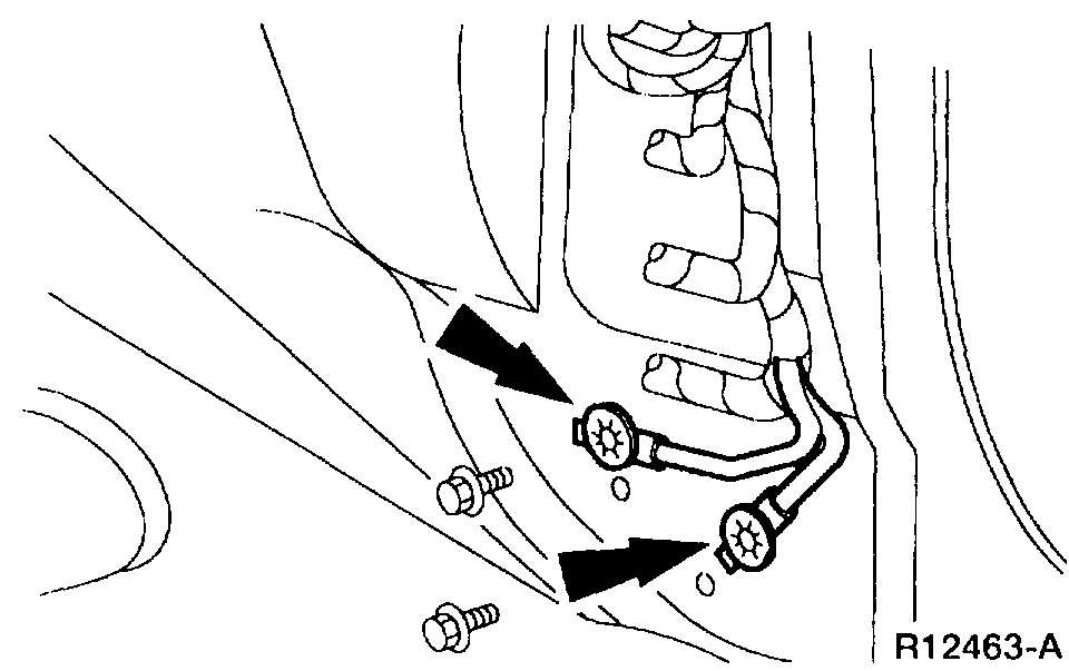
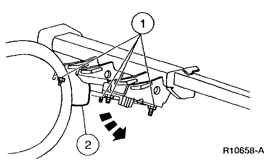
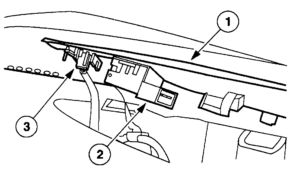
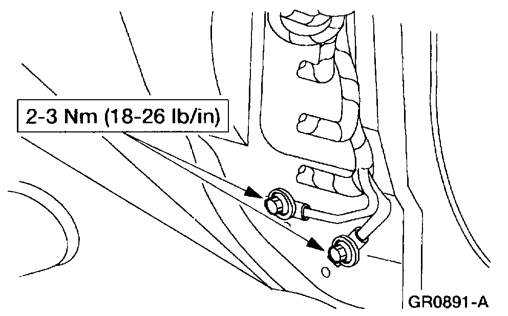
7. Remove the (A) radio ground and the (B) GEM/CTM ground bolts.
Pic 6
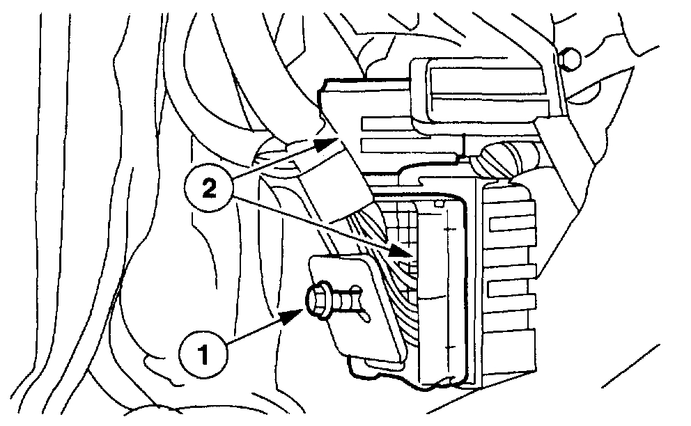
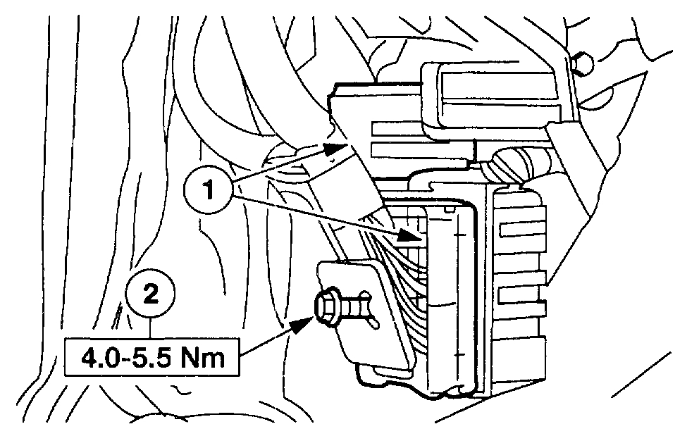
8. Disconnect the LH instrument panel main harness connectors.
1 Loosen the bolt.
2 Disconnect the LH instrument panel main harness connectors.
Pic 7
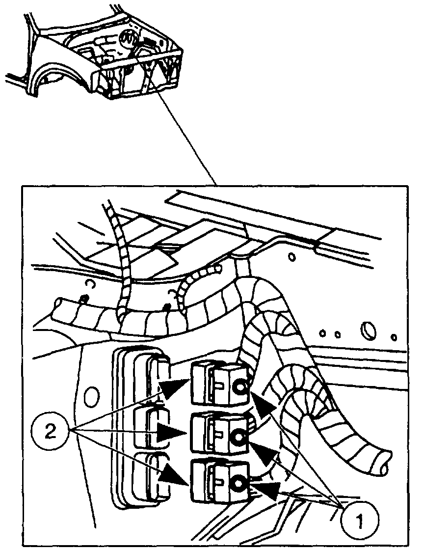
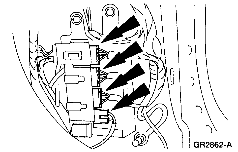
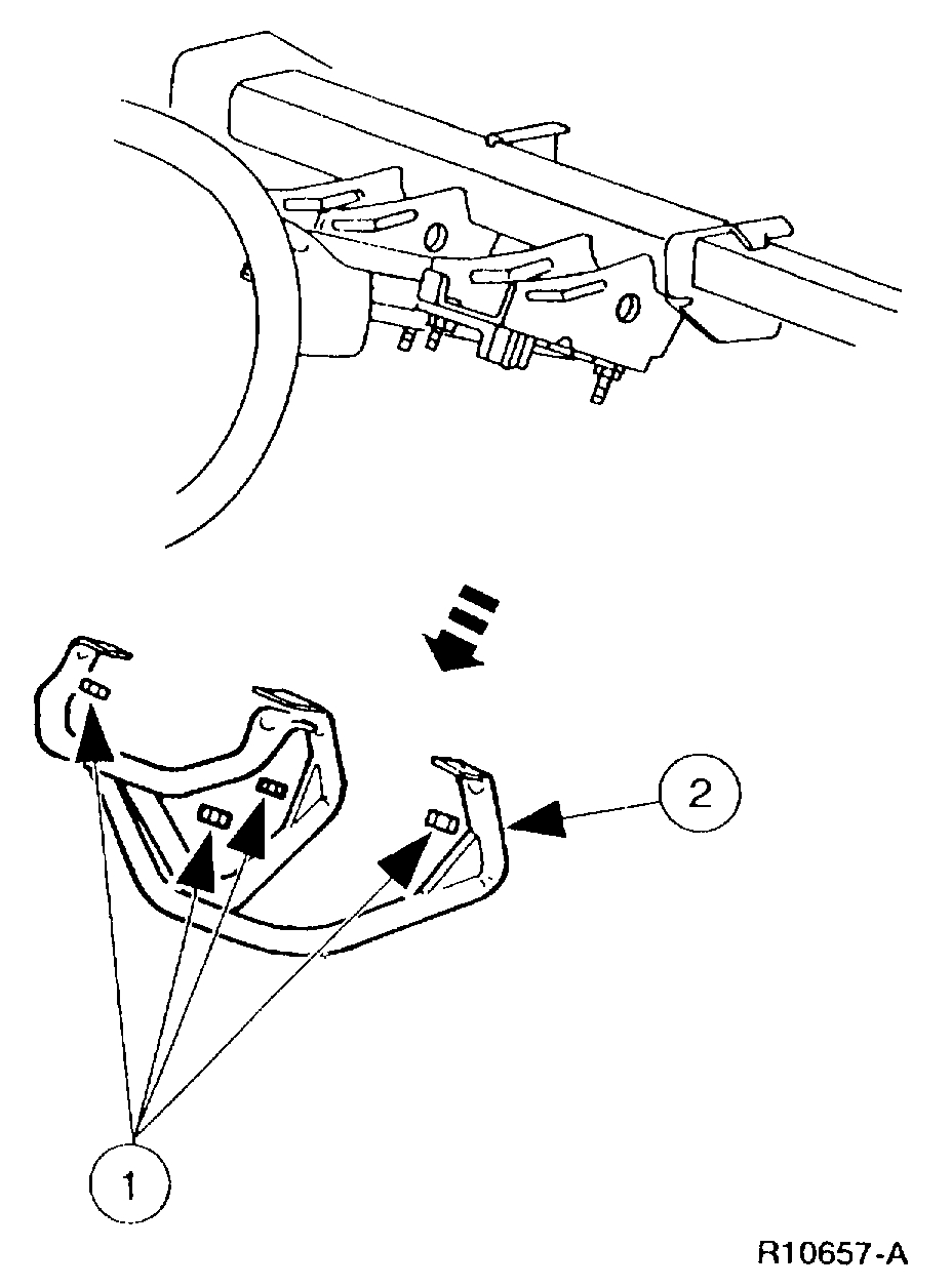
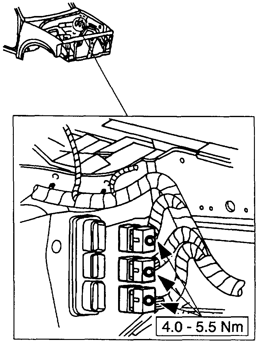
9. Remove the bulkhead wiring harness electrical connectors from inside the engine compartment.
1 Loosen the bolts.
2 Disconnect the bulkhead electrical connectors.
Pic 8
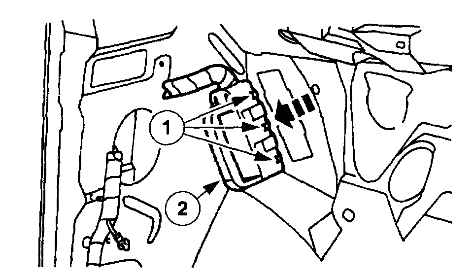
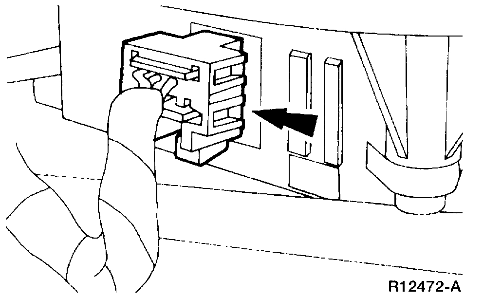
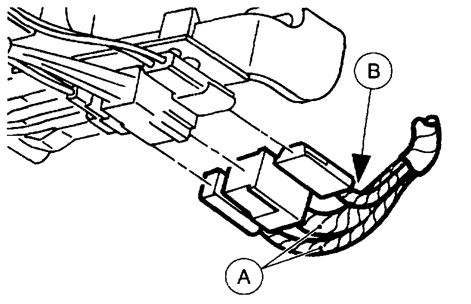
10. Remove the bulkhead electrical connector from the dash panel.
1 Release the six locking tabs.
2 Remove the bulkhead electrical connector from the dash panel.
Pic 9
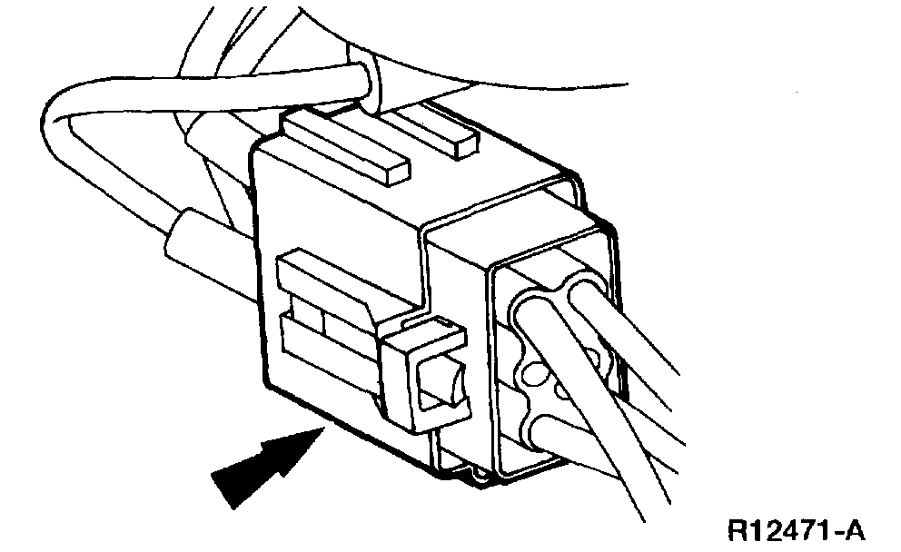
11. Disconnect the air bag diagnostic monitor electrical connectors.
Pic 10
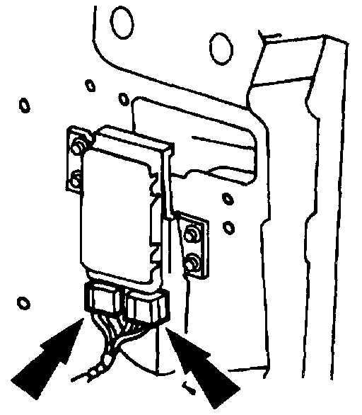
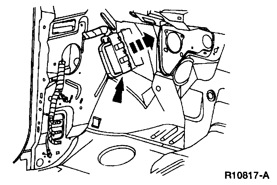
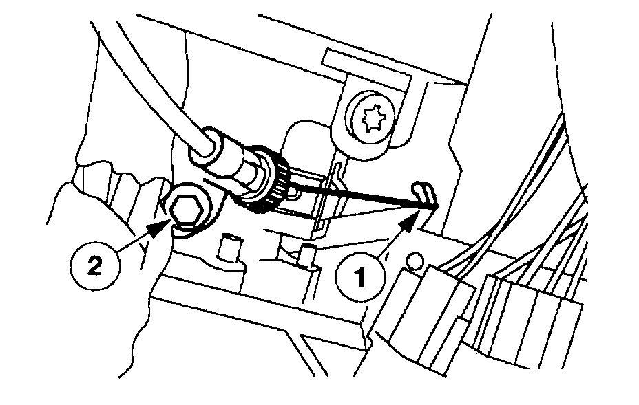
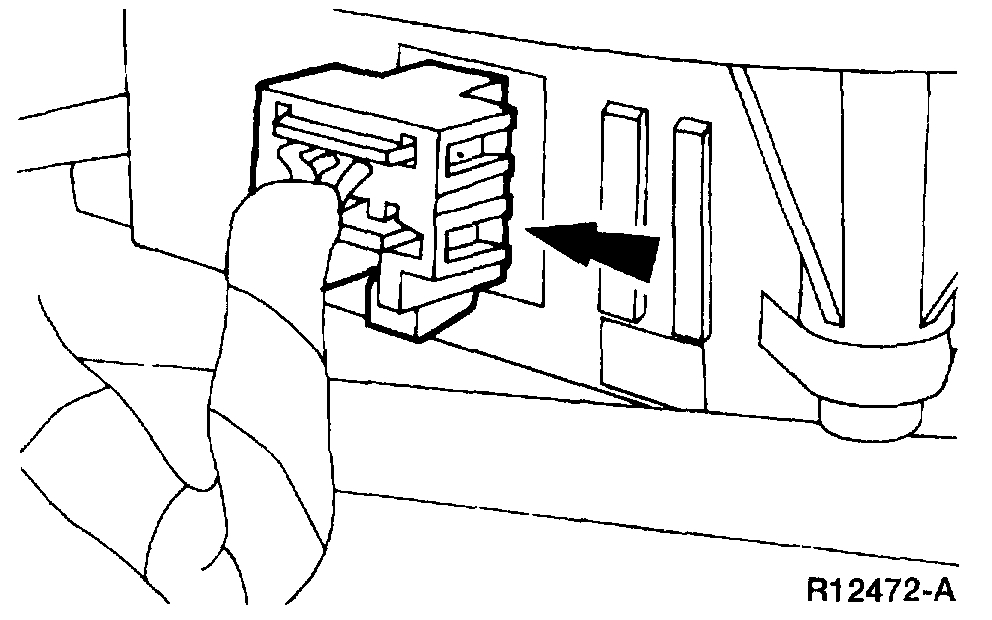
12. Disconnect the inertia fuel shutoff switch electrical connector.
Pic 11
13. Remove the RH ground bolts.
Pic 12
14. Disconnect the RH instrument panel main harness connectors.
Pic 13
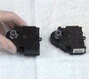
15. Disconnect the electronic actuator electrical connector.
Pic 14
16. Disconnect the climate control head vacuum line connector.
Pic 15
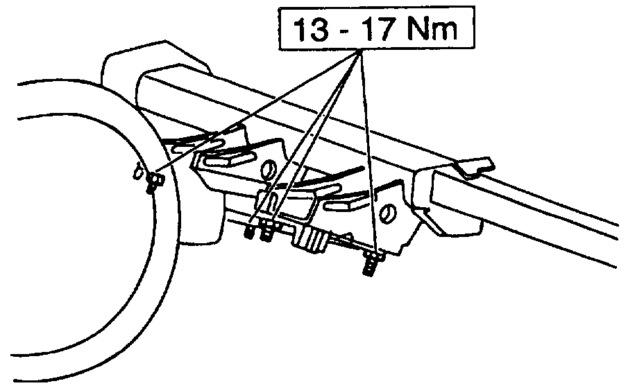
17. Remove the instrument panel steering column opening cover reinforcement.
1 Remove the nuts.
2 Remove the instrument panel steering column opening cover reinforcement.
Pic 16
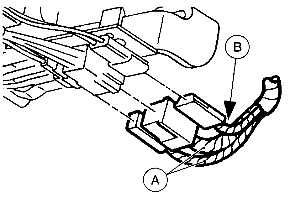
18. Disconnect the (A) air bag sliding contact electrical connectors and the (B) anti-theft sensor electrical connector.
Pic 17
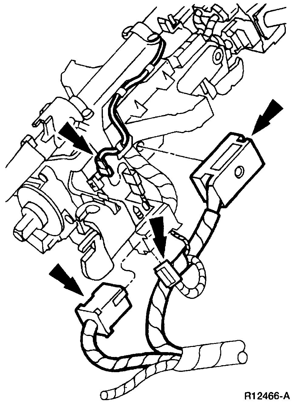
19. Disconnect the remaining electrical connectors on the steering column.
Pic 18
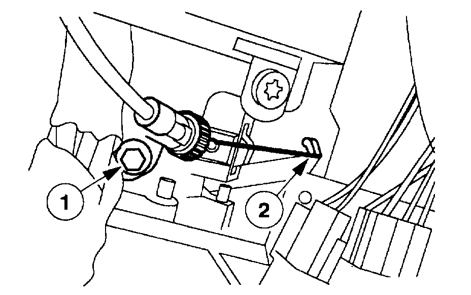
20. If equipped, disconnect the transmission range indicator from the steering column.
1 Remove the bolt.
2 Disconnect the cable.
Pic 19
21. Lower the steering column.
1 Remove the nuts.
2 Lower the steering column.
Pic 20
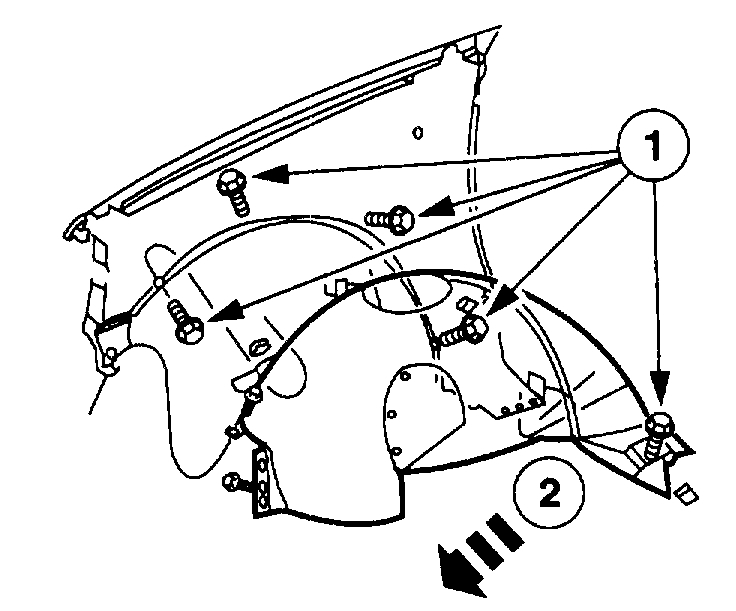
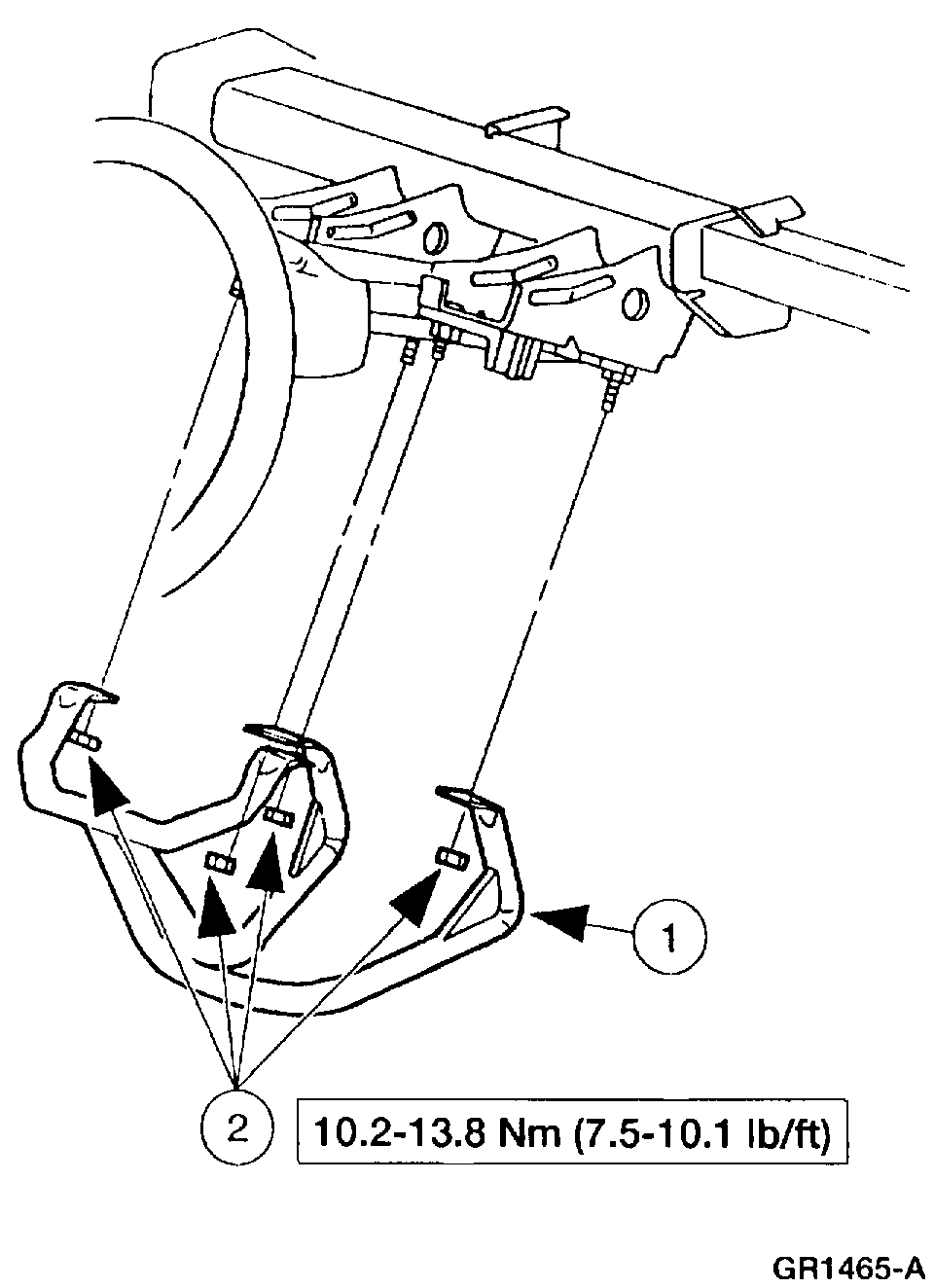
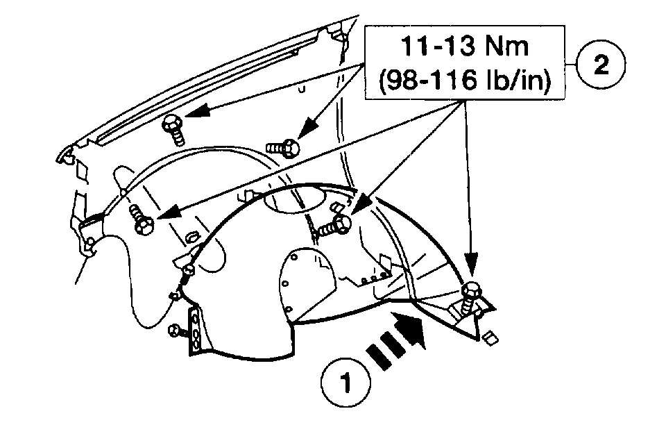
22. Position the RH front fender splash shield away from the dash panel.
1 Remove the screws.
2 Position the RH front fender splash shield away from the dash panel.
Pic 21
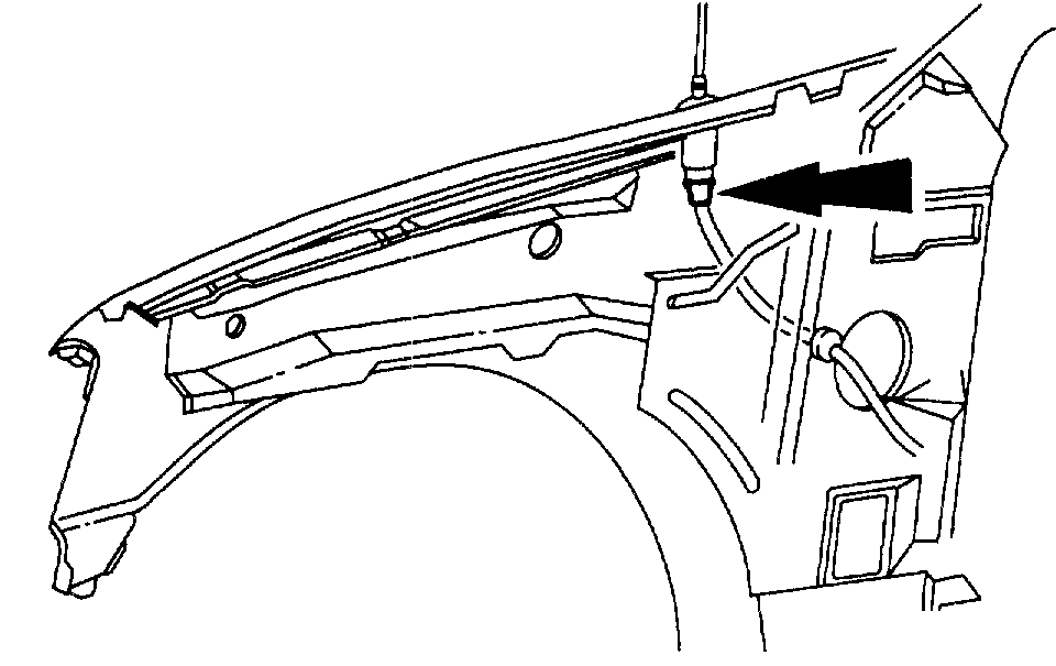
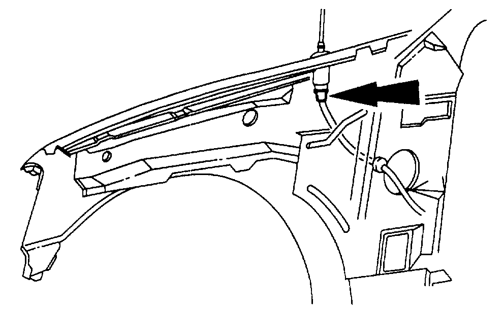
23. Disconnect the antenna lead in cable from the antenna base.
Pic 22
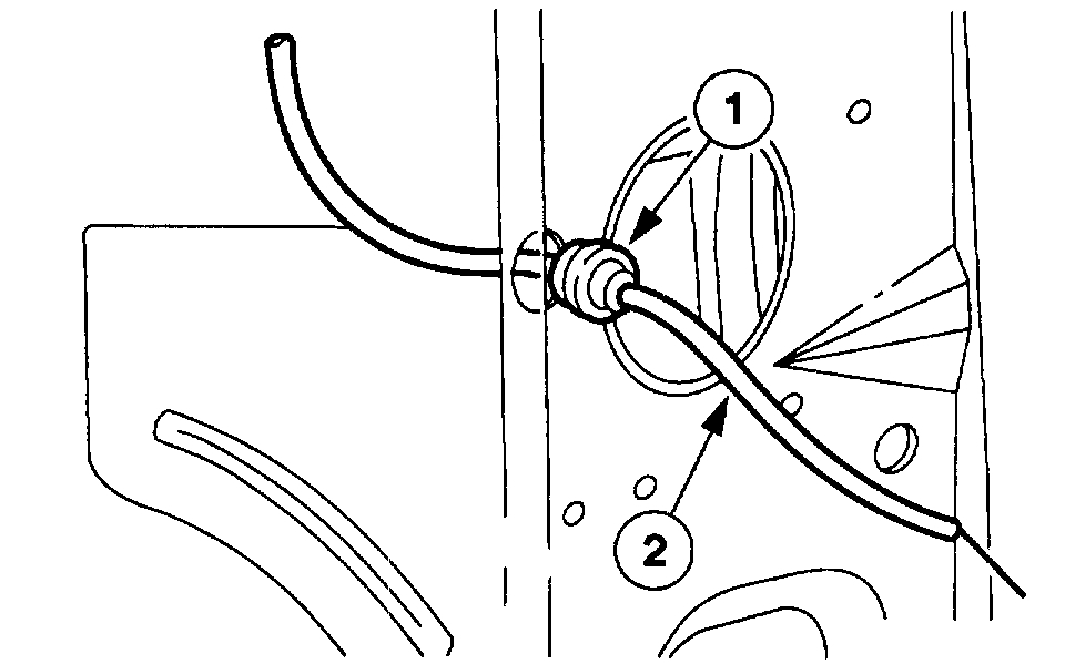
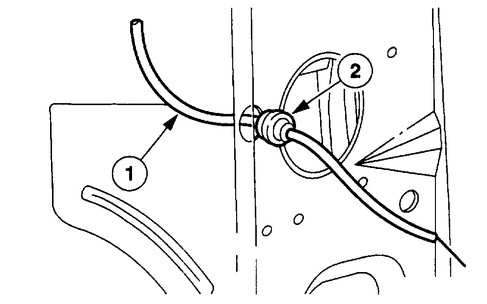
24. Feed the antenna lead in cable through the cowl side panel.
1 Unseat the antenna lead in cable grommet.
2 Feed the antenna lead in cable through the cowl side panel.
Pic 23
25. Remove the instrument panel relay cover.
1 Remove the cover.
2 If equipped, disconnect the autolamp sensor.
3 If equipped, disconnect the sunload sensor.
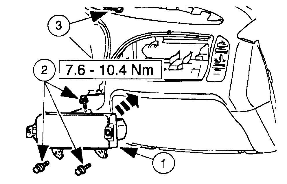
26. Remove the glove compartment.
Pic 24
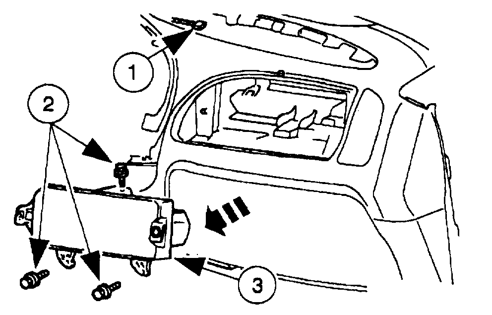
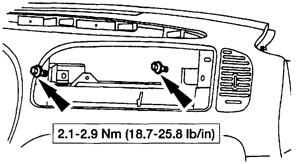
27. Remove the passenger side air bag module.
1 Disconnect the electrical connector.
2 Remove the screws.
3 Remove the passenger side air bag module.
Warning:
*Always wear safety glasses when removing and handling an air bag.
*Carry a live air bag with the bag and trim cover pointed away from your body. An accidental deployment will then deploy with minimal chance of injury.
*Place a live air bag on a bench or other surface with the trim cover up.
Pic 25
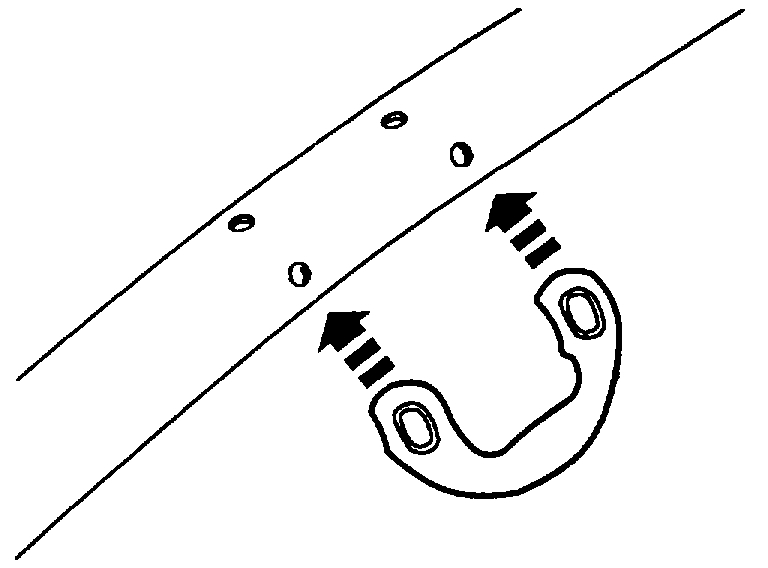
28. Remove the RH assist handle screw covers.
Pic 26
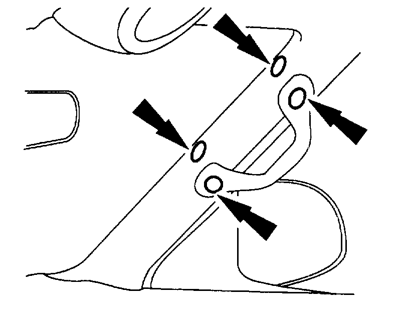
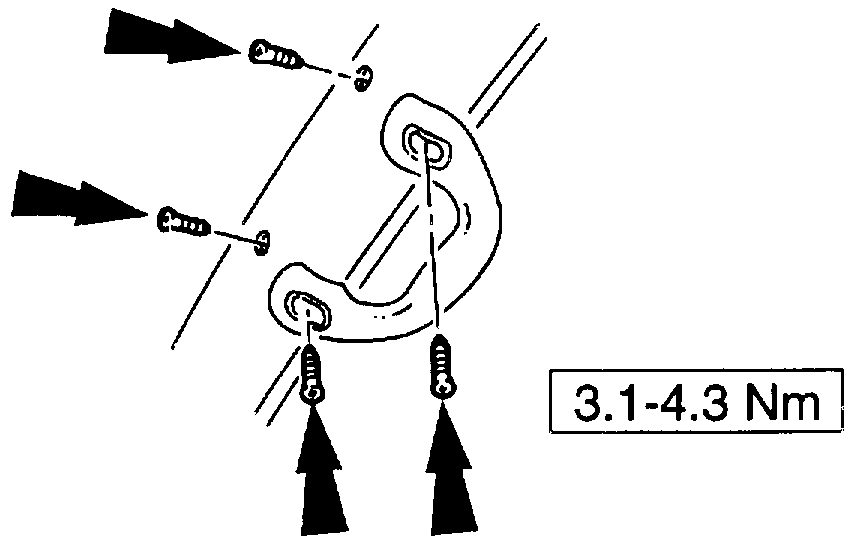
29. Remove the RH assist handle screws.
Pic 27
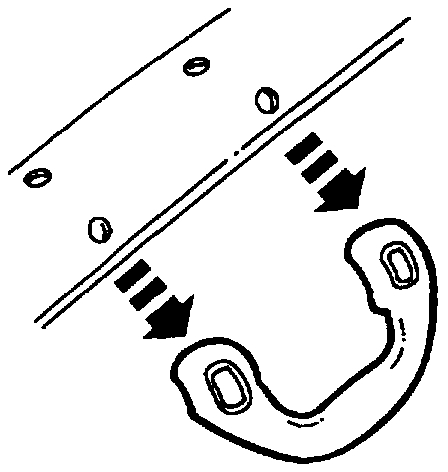
30. Remove the RH assist handle.
Pic 28
31. Position the LH and RH door weather-strip seals aside.
Pic 29
32. Remove the RH and LH windshield side garnish mouldings.
Pic 30
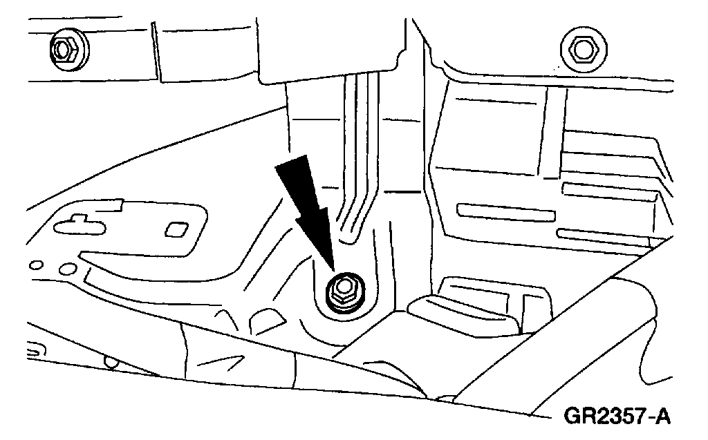
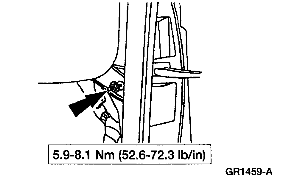
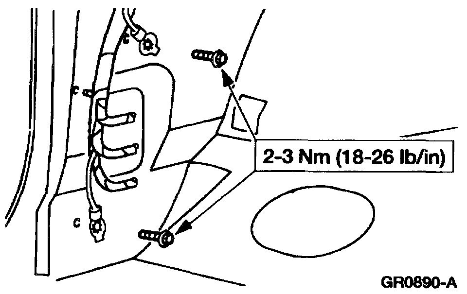
33. Remove the instrument panel reinforcement bolt below the LH corner of the glove compartment.
Pic 31
34. Remove the instrument panel bolts through the passenger side air bag module opening.
Pic 32
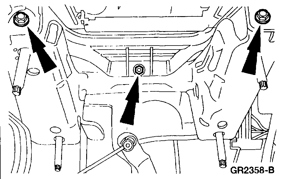
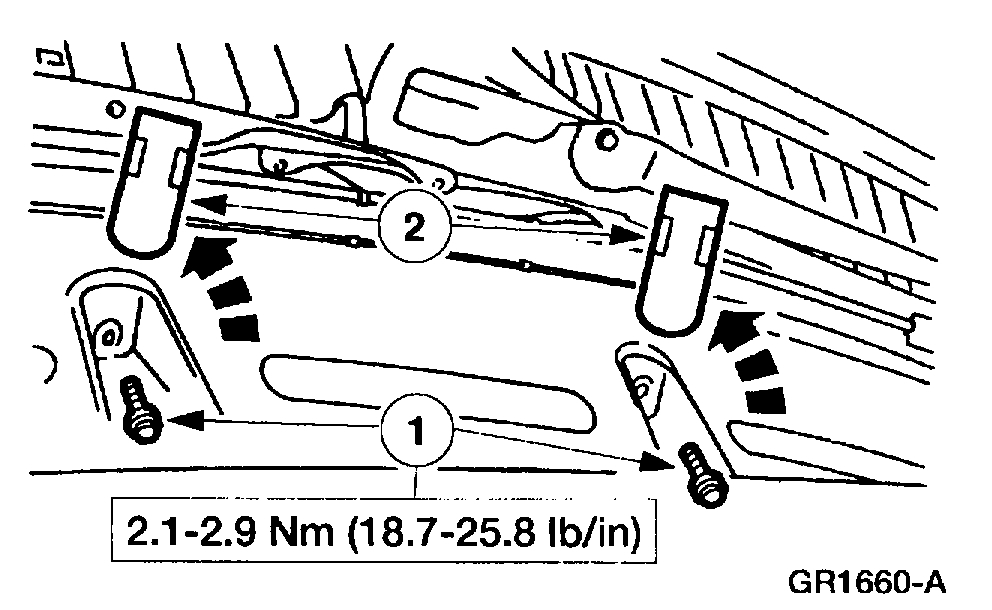
35. Remove the instrument panel cowl top bolts.
1 Remove the covers.
2 Remove the bolts.
Pic 33
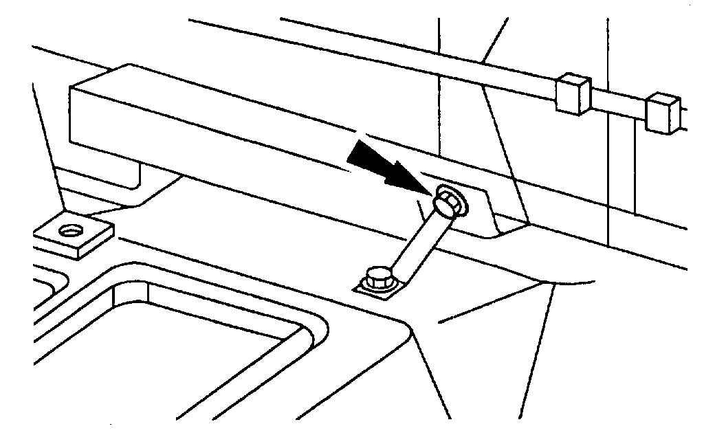
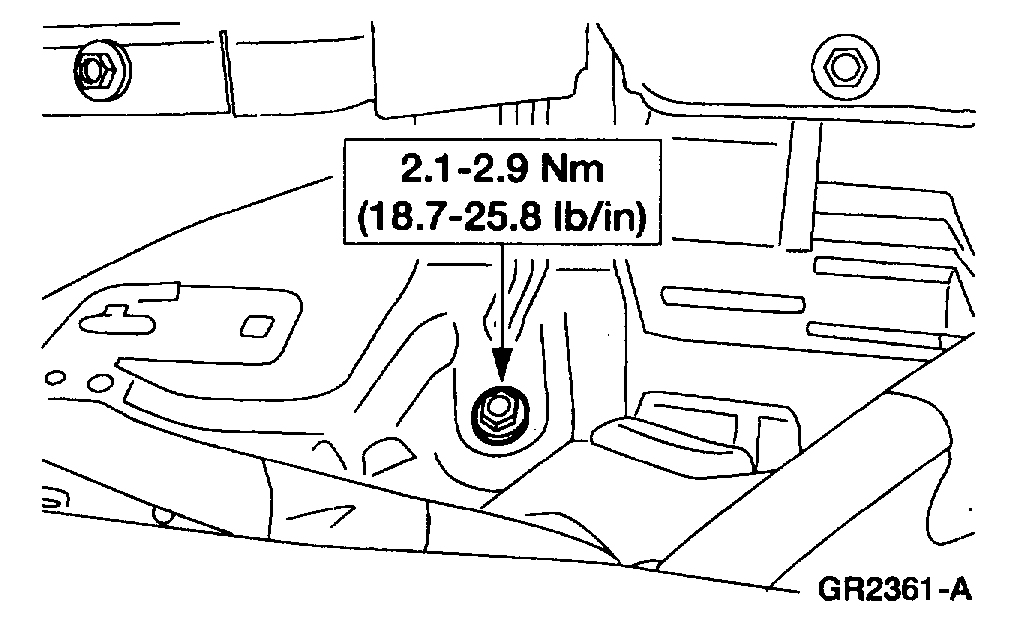
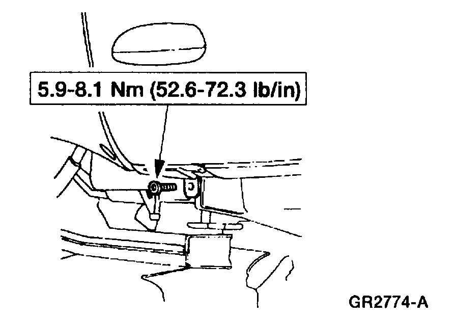
36. Remove the instrument panel bolt on the relay bracket.
Pic 34
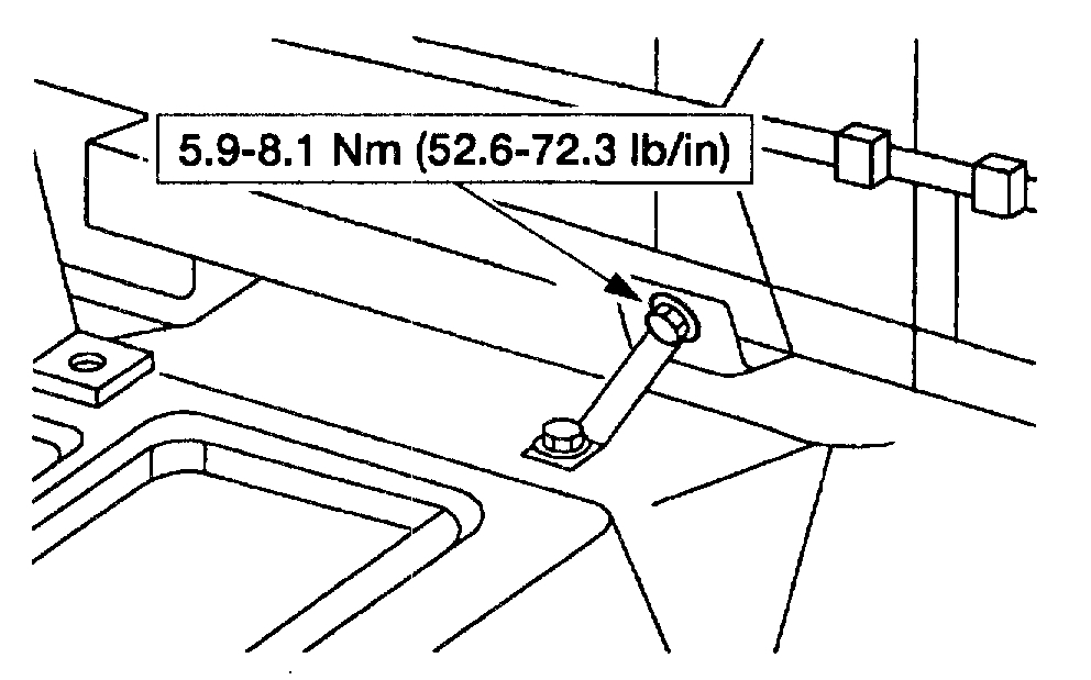
37. Remove the instrument panel reinforcement bolt below LH corner of the cigar lighter and power point.
Pic 35
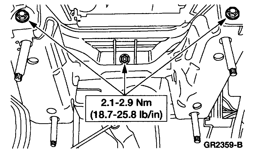
38. Remove the RH instrument panel cowl side nut.
Pic 36
39. Remove the LH instrument panel cowl side nut.
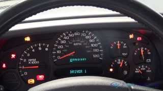
Pic 37
40. Remove the instrument panel bolts through the steering column opening.
Pic 38
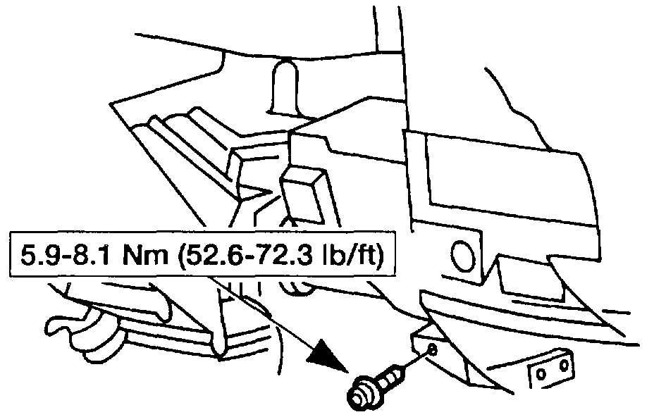
41. Remove the instrument panel to floor brace bolt.
Pic 39
22
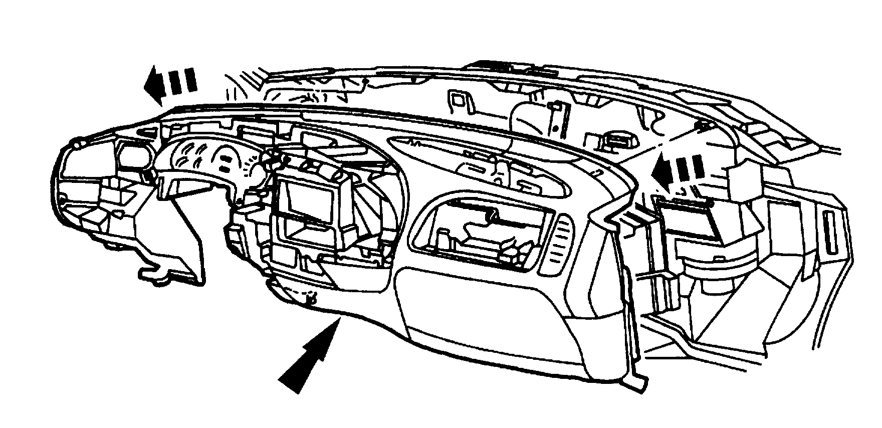
42. Remove the instrument panel.
NOTE: Two bullet connectors secure the instrument panel to the bulkhead.
___________________________________________________________________________________
Install
1998 Ford Truck Expedition 4WD V8-5.4L SOHC VIN L
Installation
Vehicle Body and Frame Interior Moulding / Trim Dashboard / Instrument Panel Service and Repair Procedures Instrument Panel - Replacement Installation
INSTALLATION
INSTALLATION
pic 40
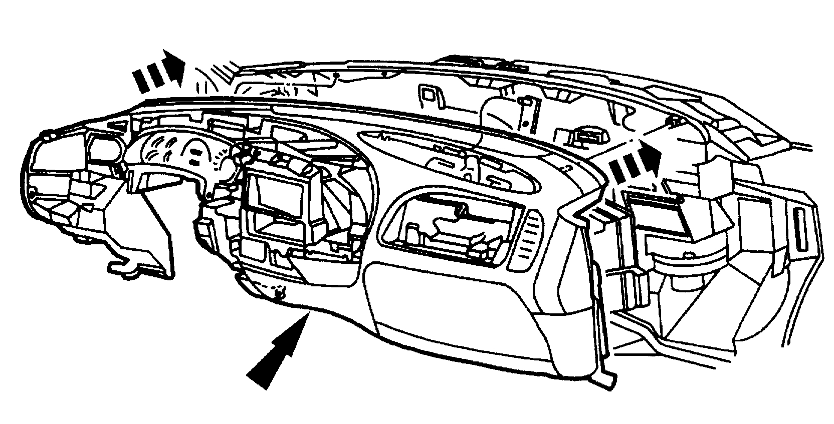
1. Position the instrument panel.
Align and seat the instrument panel to the bulkhead.
Pic 41
2. Connect the air bag diagnostic monitor electrical connectors.
Pic 42
3. Connect the inertia fuel shutoff switch electrical connector.
Pic 43
4. Connect the bulkhead electrical connector harness.
Pic 44
5. Install the bulkhead wiring harness electrical connectors from inside the engine compartment.
Pic 45
6. Install the instrument panel bolts through the passenger side air bag module opening.
Install the RH bolt first.
Pic 46
7. Install the instrument panel bolts through the steering column opening.
Pic 47
8. Install the LH instrument panel cowl side nut.
Pic 48
9. Install the RH instrument panel cowl side nut.
Pic 49
10. Install the instrument panel cowl top bolts.
1 Install the bolts.
2 Install the covers.
Pic 50
11. Install the instrument panel bolt on the relay bracket.
Pic 51
12. Install the instrument panel reinforcement bolt below the LH corner of the cigar lighter and power point.
Pic 52
13. Install the instrument panel reinforcement bolt below the LH corner of the glove compartment.
Pic 53
14. Install the instrument panel to floor brace bolt.
Pic 54
15. Connect the radio ground and the GEM/CTM ground bolts.
Pic 55
16. Connect the LH instrument panel main harness connectors.
1 Connect the instrument panel main harness connectors.
2 Tighten the bolt.
Pic 56
17. Connect the Brake Pedal Position (BPP) switch electrical connector.
Pic 57
18. Install the RH ground bolts.
Pic 58
19. Connect the RH instrument panel main harness connectors.
Pic 59
20. Install the LH and RH cowl side trim panels.
Pic 60
21. Install the LH and RH scuff plates.
Pic 61
22. Install the RH and LH windshield side garnish mouldings.
Pic 62
23. Position the RH assist handle.
Pic 63
24. Install the RH assist handle screws.
Pic 64
25. Install the RH assist handle screw covers.
Pic 65
26. Install the LH and RH door weather-strip seals into the proper position.
Pic 66
27. Install the passenger side air bag module.
1 Position the passenger side air bag module.
2 Install the bolts.
NOTE: Install the top bolt first.
3 Connect the electrical connector.
Warning:
*Never probe the connectors on the air bags. Doing so may result in air bag deployment, which could result in personal injury.
*Always wear safety glasses when handling an air bag.
*Carry a live air bag with the bag and trim cover pointed away from your body. An accidental deployment will then deploy with a minimal chance of injury.
28. Install the glove compartment.
Pic 67
29. Install the instrument panel relay cover.
1 If equipped, connect the sunload sensor.
2 If equipped, connect the autolamp electrical connector.
3 Install the instrument panel relay cover.
Pic 68
30. Position the steering column.
Install the steering column support nuts.
Pic 69
31. If equipped, connect the transmission range indicator to the steering column.
1 Connect the cable.
2 Install the bolt.
Pic 70
32. Install the instrument panel steering column opening cover reinforcement.
1 Position the instrument panel steering column opening cover reinforcement.
2 Install the nuts.
Pic 71
33. Connect the (A) air bag sliding contact electrical connectors and the (B) anti-theft sensor electrical connector.
Pic 72
34. Connect the remaining electrical connectors on the steering column.
Pic 73
35. Feed the antenna lead in cable through the cowl side panel.
1 Feed the antenna lead in cable through the cowl side panel.
2 Seat the antenna lead in cable grommet.
Pic 74
36. Connect the antenna lead in cable to the antenna base.
Pic 75
37. Install the RH front fender splash shield.
1 Position the RH front fender splash shield.
2 Install the screws.
Pic 76
38. Connect the electronic actuator electrical connector.
Pic 77
39. Connect the climate control head vacuum line connector.
40. Install the instrument panel steering column cover.
41. If equipped, install the front floor console assembly.
Pic 78
42. Install the battery cables.
Note: When the battery is disconnected and reconnected, some abnormal drive symptoms may occur while the vehicle relearns its adaptive strategy. The vehicle may need to be driven 16 km (10 mi) or more to relearn the strategy.
____________________________________
I hope this helps.
Take care,
Joe
Images (Click to make bigger)
Saturday, November 21st, 2020 AT 10:27 PM