Thank you.
I doubt this is a crankshaft position sensor at all. Is a correlation issue between the cam and crank sensors.
On your model, you have a distributor, which is a cam sensor. The gear at the bottom wears out and changes the timing or the setting between the sensors. When this happens, this code is set.
https://www.2carpros.com/articles/camshaft-angle-sensor-replacement
You will need to pull the distributor and examine the gear at the bottom. You may have to replace the gear if it is worn.
Then when you reinstall the distributor, you will need a scan tool to set the cam retard so the correlation is correct.
Roy
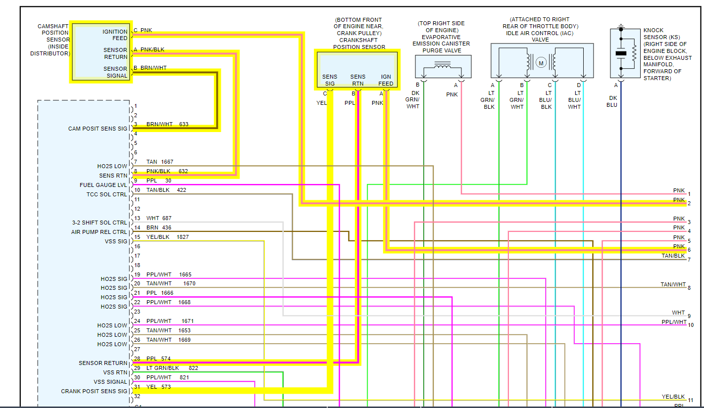
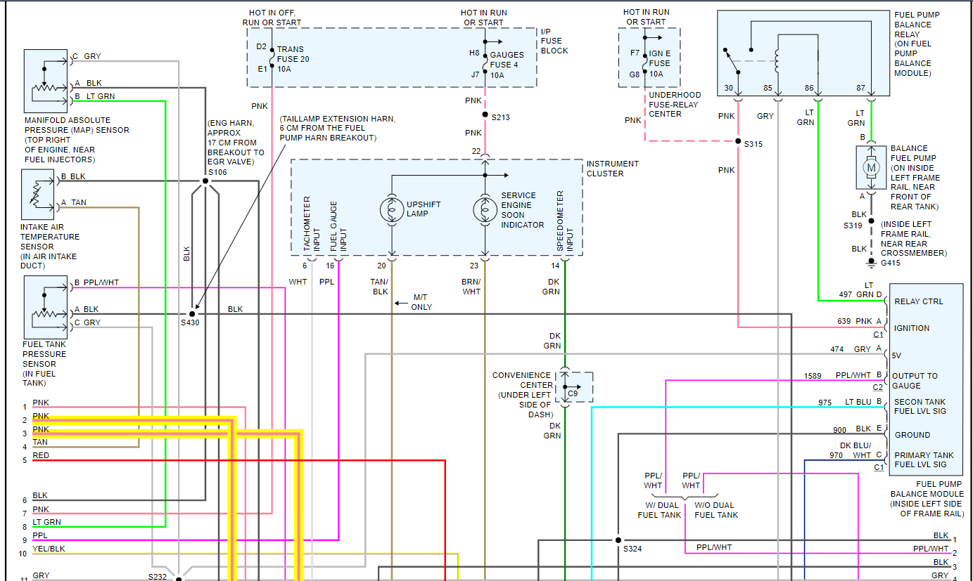
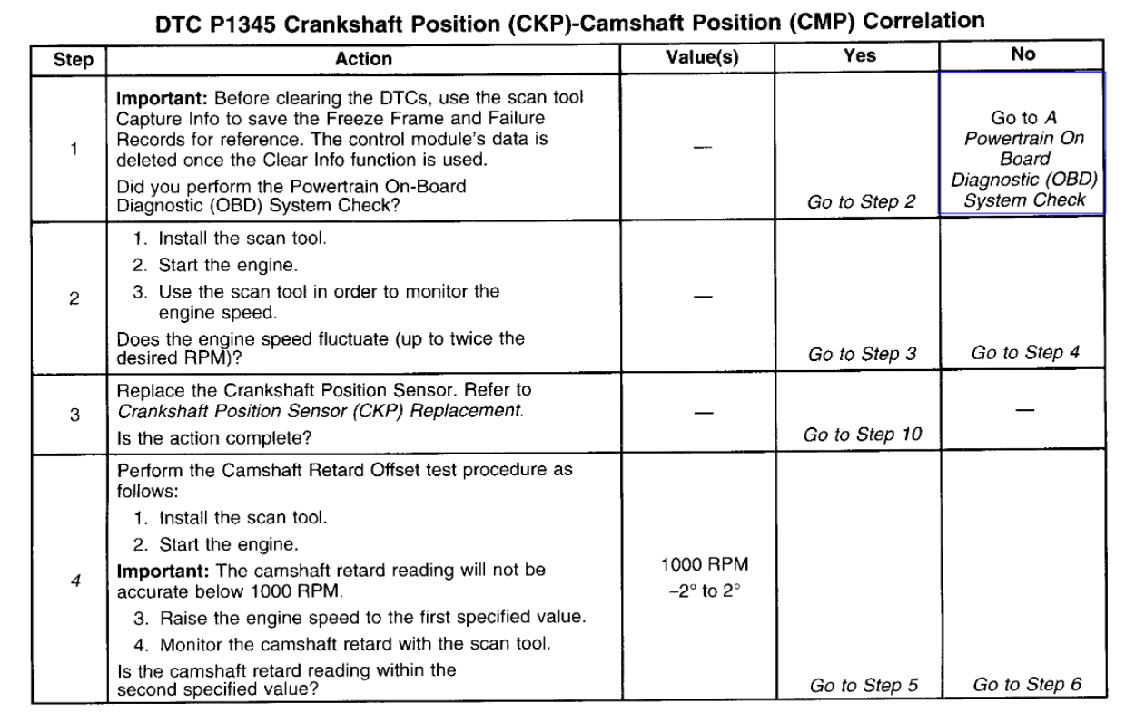
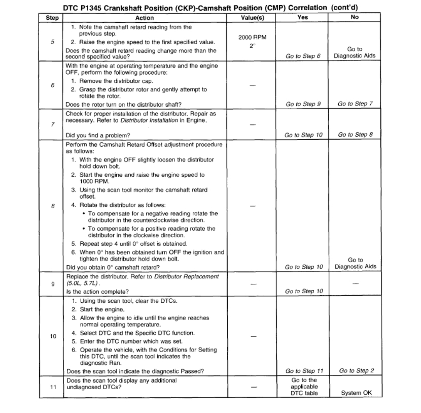
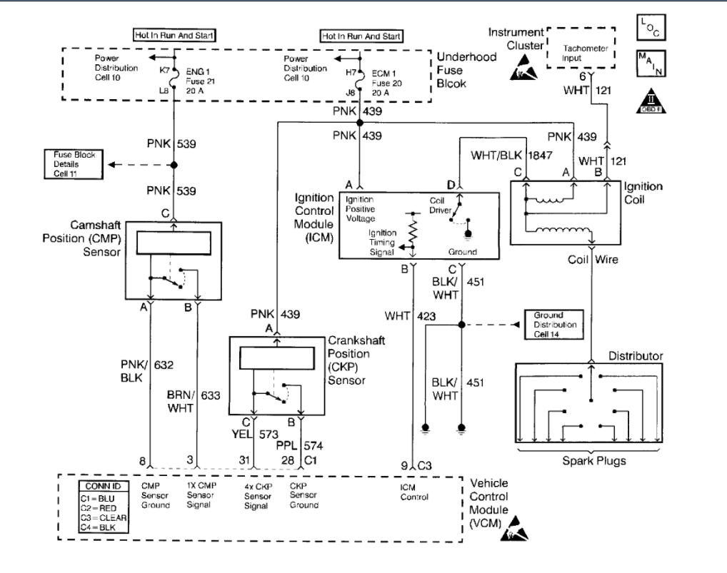
Circuit Description
This DTC monitors the CKP and CMP signals to determine if they are synchronized. If both signals are not observed by the Control Module (PCM/VCM) within a narrow time window, the VCM will determine that an error has occurred.
Conditions for Running the DTC
The engine is running
Conditions for Setting the DTC
When the engine is running, the cam sensor reference pulse is not detected at the correct position relative to the crankshaft position sensor pulse.
Action Taken When the DTC Sets
The Control Module illuminates the Malfunction Indicator Lamp (MIL) the first time the diagnostic runs and fails.
The Control Module will set the DTC and records the operating conditions at the time the diagnostic fails. The Control Module stores the failure information in the scan tools Freeze Frame and/or the Failure Records.
Conditions for Clearing the MIL/DTC
The Control Module turns OFF the MIL after 3 consecutive drive trips when the test has Run and Passed.
A history DTC will clear if no fault conditions have been detected for 40 warm-up cycles (coolant temperature has risen 22°C (40°F) from the start-up coolant temperature and the Engine Coolant Temperature is more than 70°C (158°F) during the same ignition cycle).
Use the scan tool Clear Information function.
Diagnostic Aids
Check the following items:
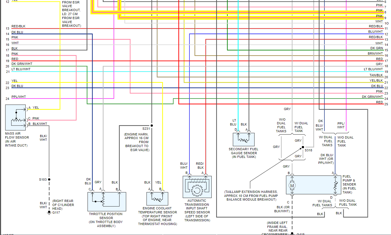
A loose CMP sensor causing a variance in the sensor signal
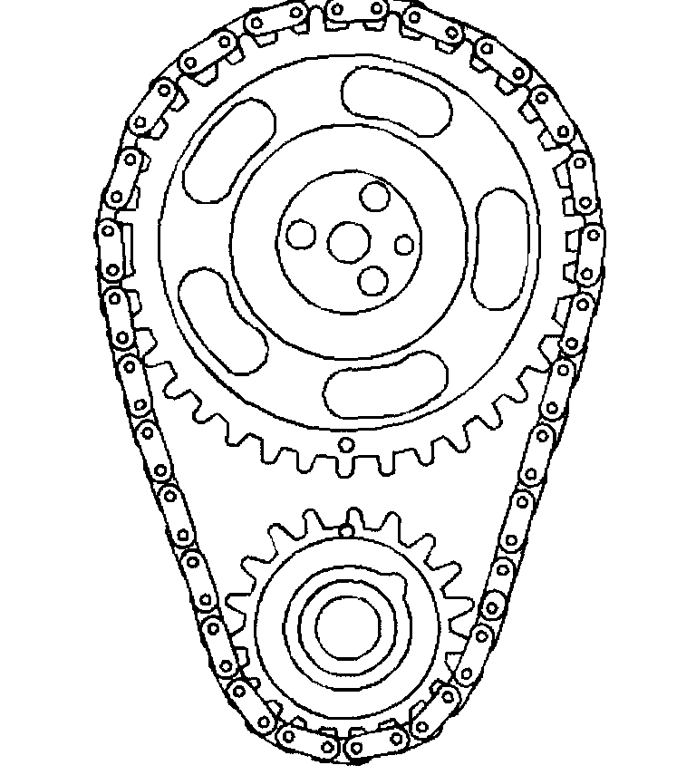
Excessive free play in the timing chain and gear assembly
Incorrectly installed distributor - 1 tooth off in either advance or retard positions
A loose distributor rotor on the distributor shaft
A loose or missing distributor hold down bolt.
An intermittent may be caused by any of the following conditions:
A poor connection
Rubbed through wire insulation
A broken wire inside the insulation
Thoroughly check any circuitry that is suspected of causing the intermittent complaint. Refer to Intermittents and Poor Connections Diagnosis. See: Computers and Control Systems > Symptom Related Diagnostic Procedures
Test Description
The numbers below refer to the step numbers on the table.
4. This test will determine if this DTC is intermittent.
5. When the engine speed is raised to 2000 RPM the camshaft retard offset should not vary more than 2 degrees.
6. If excessive pressure is used when performing this test unintentional damage to the distributor shaft could result.
7. If the distributor is one tooth off in either the advanced or retard positions the vehicle may run but 0 degrees camshaft retard offset will not be obtained.
8. If 0 degrees cannot be obtained during this procedure refer to Diagnostic Aids.
Distributor
DISTRIBUTOR REPLACEMENT
REMOVAL PROCEDURE
NOTE: There are two procedures available to install the distributor.
Use Installation Procedure 1 when the crankshaft has NOT been rotated from the original position.
Use Installation Procedure 2 when any of the following components are removed:
The intake manifold.
The cylinder head.
The camshaft.
The timing chain or sprockets.
The complete engine.
If the Malfunction Indicator Lamp turns on, and a DTC code P1345 sets after installing the distributor, this indicates an incorrectly installed distributor.
Engine damage or distributor damage may occur. Use Procedure 2 in order to install the distributor.
1. Turn OFF the ignition switch.
Remove the spark plug wires from the distributor cap.
Twist each spark plug 1/2 turn.
Pull only on the boot in order to remove the wire from the distributor cap.
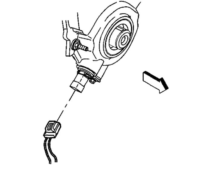
2. Remove the electrical connector from the base of the distributor.
imageOpen In New TabZoom/Print
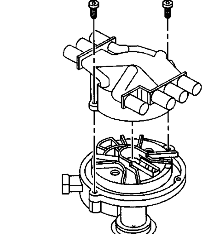
3. Remove the two screws that hold the distributor cap to the housing.
4. Discard the screws.
5. Remove the distributor cap from the housing.
imageOpen In New TabZoom/Print
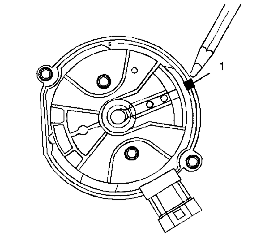
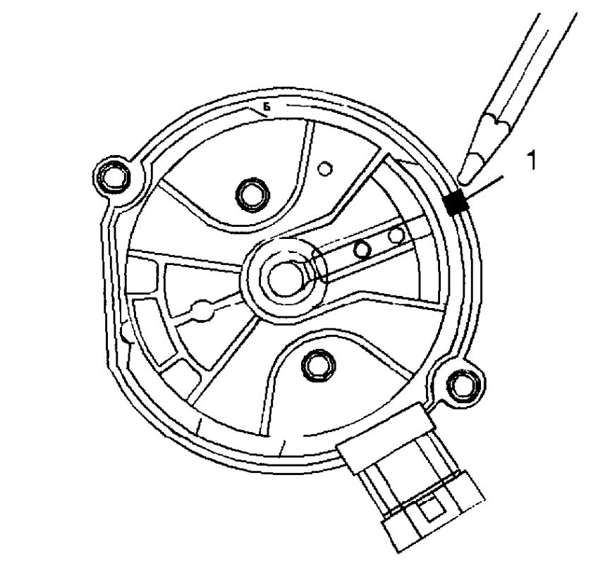
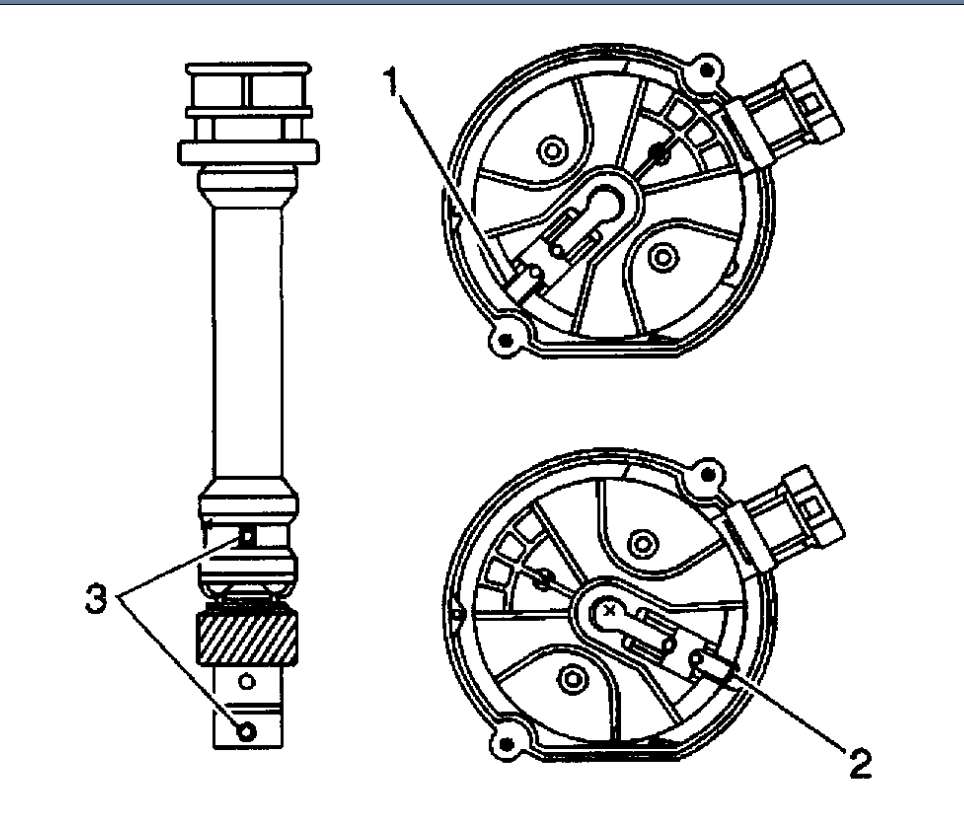
6. Use a grease pencil in order to note the position of the rotor in relation to the distributor housing (1).
7. Mark the distributor housing and the intake manifold with a grease pencil.
imageOpen In New TabZoom/Print
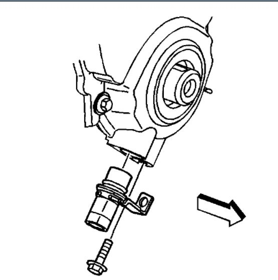
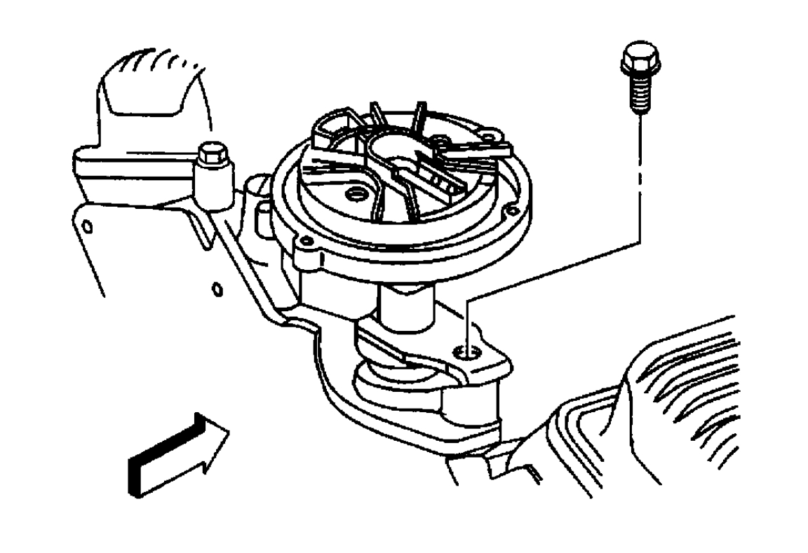
8. Remove the mounting clamp hold down bolt.
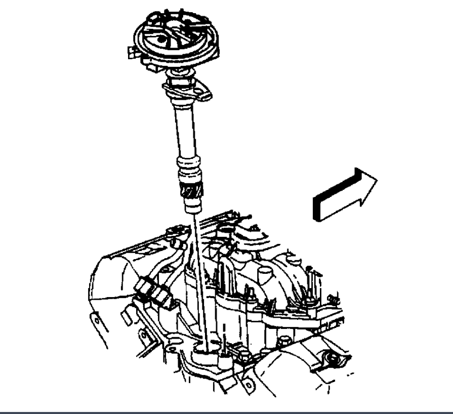
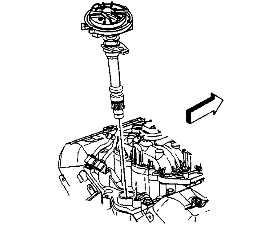
9. Remove the distributor.
imageOpen In New TabZoom/Print
10. As the distributor is being removed from the engine watch the rotor move in a counter-clockwise direction about 42 degrees. This will appear as slightly more than one clock position.
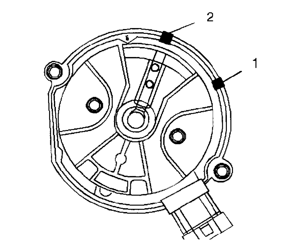
11. Note the position of the rotor segment.
11.1.Place a second mark on the base of the distributor.
This will aid in achieving proper rotor alignment during the distributor installation.
11.2.The second mark on the distributor housing is identified in the graphic as number 2.
INSTALLATION PROCEDURE 1
imageOpen In New TabZoom/Print
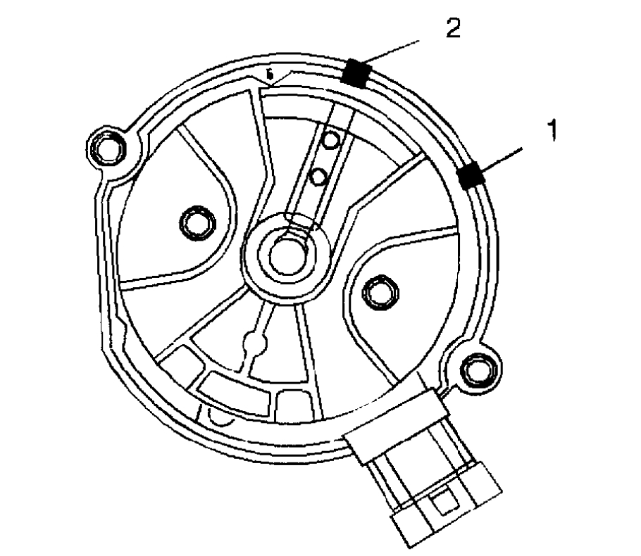
1. If installing a new distributor assembly, place two marks on the new distributor housing in the same location as the two marks on the original housing.
2. Remove the new distributor cap, if necessary.
3. Align the rotor with mark made at location 2.
imageOpen In New TabZoom/Print
4. Guide the distributor into the engine.
5. Align the hole in the distributor hold-down base over the mounting hole in the intake manifold.
imageOpen In New TabZoom/Print
6. As the distributor is being installed, observe the rotor moving in a clockwise direction about 42 degrees.
7. Once the distributor is completely seated, the rotor segment should be aligned with the mark on the distributor base in location number 1.
If the rotor segment is not aligned with the number 1 mark, the driven gear teeth and the camshaft have meshed one or more teeth out of alignment.
In order to correct this condition, remove the distributor and reinstall it.
NOTE: Refer to Fastener Notice in Service Precautions.
imageOpen In New TabZoom/Print
8. Install the distributor mounting clamp bolt.
Tighten
Tighten the distributor clamp bolt to 25 N.m (18 lb ft).
imageOpen In New TabZoom/Print
9. Install the distributor cap.
10. Install two NEW distributor cap screws.
Tighten
Tighten the screws to 2.4 N.m (21 lb in).
11. Install the electrical connector to the distributor.
12. Install the spark plug wires to the distributor cap.
imageOpen In New TabZoom/Print
13. Install the ignition coil wire.
The wire must not touch anything like the dip slick. Rubbing will make a ground/short after time of use.
14. For V8 engines, connect a scan tool.
imageOpen In New TabZoom/Print
15. Monitor the Camshaft Retard Offset value. Refer to Computers and Control Systems Camshaft Retard Offset Adjustment.
IMPORTANT: If the Malfunction Indicator lamp is turned on after installing the distributor, and a DTC P1345 is found, the distributor has been installed incorrectly.
16. Refer to Installation Procedure 2 for proper distributor installation.
INSTALLATION PROCEDURE 2
imageOpen In New TabZoom/Print
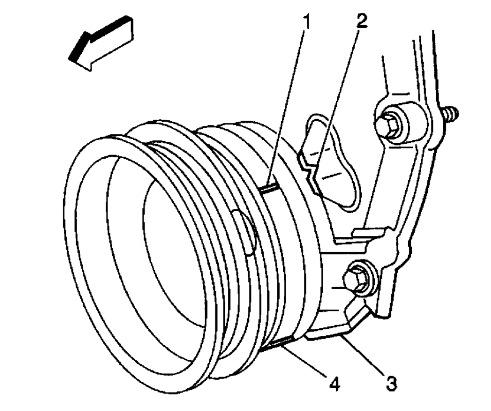
IMPORTANT: Rotate the number 1 cylinder to Top Dead Center (TDC) of the compression stroke. The engine front cover has 2 alignment tabs and the crankshaft balancer has 2 alignment marks (spaced 90 degrees apart) which are used for positioning number 1 piston at Top Dead Center (TDC). With the piston on the compression stroke and at top dead center, the crankshaft balancer alignment mark (1) must align with the engine front cover tab (2) and the crankshaft balancer alignment mark (4) must align with the engine front cover tab (3).
1. Rotate the crankshaft balancer clockwise until the alignment marks on the crankshaft balancer are aligned with the tabs on the engine front cover and the number 1 piston is at top dead center of the compression stroke.
imageOpen In New TabZoom/Print
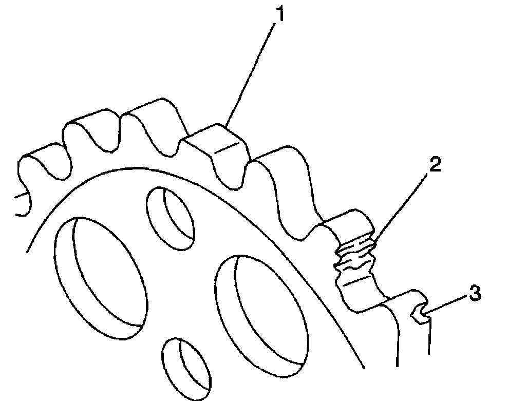
2. Align white paint mark on the bottom stem of the distributor, and the pre-drilled indent hole in the bottom of the gear (3).
NOTE: The OBD II ignition system distributor driven gear and rotor may be installed in multiple positions. In order to avoid mistakes, mark the distributor on the following components in order to ensure the same mounting position upon reassembly:
The distributor driven gear
The distributor shaft
The rotor holes
Installing the driven gear 180 degrees out of alignment, or locating the rotor in the wrong holes, will cause a no-start condition. Premature engine wear or damage may result.
3. With the gear in this position, the rotor segment should be positioned as shown for a V6 engine (1) or V8 engine (2).
The alignment will not be exact.
If the driven gear is installed incorrectly, the dimple will be approximately 180 degrees opposite of the rotor segment when the gear is installed in the distributor.
4. Using a long screw driver, align the oil pump drive shaft to the drive tab of the distributor.
imageOpen In New TabZoom/Print
5. Guide the distributor into the engine. Ensure that the spark plug towers are perpendicular to the centerline of the engine.
imageOpen In New TabZoom/Print
6. Once the distributor is fully seated, the rotor segment should be aligned with the pointer cast into the distributor base.
This pointer may have a 6 cast into it, indicating that the distributor is to be used on a 6 cylinder engine or a 8 cast into it, indicating that the distributor is to be used on a 8 cylinder engine.
If the rotor segment does not come within a few degrees of the pointer, the gear mesh between the distributor and the camshaft may be off a tooth or more.
If this is the case, repeat the procedure again in order to achieve proper alignment.
NOTE: Refer to Fastener Notice in Service Precautions.
imageOpen In New TabZoom/Print
7. Install the distributor mounting clamp bolt.
Tighten
Tighten the distributor clamp bolt to 25 N.m (18 lb ft).
imageOpen In New TabZoom/Print
8. Install the distributor cap.
9. Install two NEW distributor cap screws.
Tighten
Tighten the screws to 2.4 N.m (21 lb in).
10. Install the electrical connector to the distributor.
11. Install the spark plug wires to the distributor cap.
imageOpen In New TabZoom/Print
12. Install the ignition coil wire.
The wire must not touch anything like the dip stick. Rubbing will make a ground/short after time of use.
13. For V8 engines, connect a scan tool.
imageOpen In New TabZoom/Print
14. Monitor the Camshaft Retard Offset value. Refer to Computers and Control Systems Camshaft Retard Offset Adjustment.
IMPORTANT: If the Malfunction Indicator lamp is turned on after installing the distributor, and a DTC P1345 is found, the distributor has been installed incorrectly.
15. Refer to Installation Procedure 2 for proper distributor installation.
Images (Click to make bigger)
Friday, November 13th, 2020 AT 5:57 PM