Timing chain replacement

Tiny
MARK FRIZZELL
  • MEMBER
  • 2012 LAND ROVER LR4
  • 5.0L
  • V8
  • 4WD
  • AUTOMATIC
  • 68,000 MILES
Have read many blogs on cassettes problems on this vehicle, I have one.
I have searched for the parts two -tension-er's and guides (new upgrades).
But not sure what correct part numbers for the upgraded tension-er's and the guides with the metal at the contact of tension-er area. Any information will help. I do not know if I am buying old new stock or the upgraded version.

Thanks, Mark
Tuesday, June 19th, 2018 AT 6:41 AM

84 Replies

Tiny
KEN L
  • MASTER CERTIFIED MECHANIC
  • 42,961 POSTS
Hello,

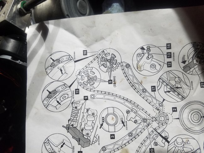
Here are the correct part numbers for the timing chain guides and tension-er's along with diagrams to show you how to do the job:

Parts Information OEM Part # Price
Timing Chain Guide
18 - Tensioner Guide LR051013 $70.98
Chain Guide 19 - Right LR051011 $38.63
19 - Left LR051012 $38.63
17 - Timing Chain LR032048 $98.60
20 - Chain Tensioner LR051008 $129.53
22 - Timing Chain, Intermediate Gear
Includes: Intermediate Gear. LR067417 $381.61

Timing Drive Components
This is a "Trustmark Authoring Standards (TAS) Repair Procedure"
TAS style procedures can be identified by steps that have no accompanying step text and the magenta color of the electrical connectors and fasteners such as nuts, bolts, clamps or clips.
TAS removal and installation procedures use a sequence of color illustrations to indicate the order to be followed when removing/disassembling or installing/assembling a component.
Many of the TAS procedures will have the installation information within the removal steps.
The TAS color illustrations use a variety of symbols to indicate important details of the procedures. It is important to understand these symbols in order to properly used the TAS procedures. Refer to How to Use TAS Procedures and TAS Symbol Glossary at Vehicle | Description and Operation for additional information on these TAS procedures.
For additional information, refer to How to Use TAS Procedures See: Description and OperationHow to Use TAS Procedures

Removal

Caution: Check all timing components for wear and install new components if required.

Note:
Removal steps in this procedure may contain installation details.

Note:
Some variation in the illustrations may occur, but the essential information is always correct.
1 Disconnect the battery ground cable.
For additional information, refer to Specifications
Warning: Make sure to support the vehicle with axle stands.
2 Raise and support the vehicle.

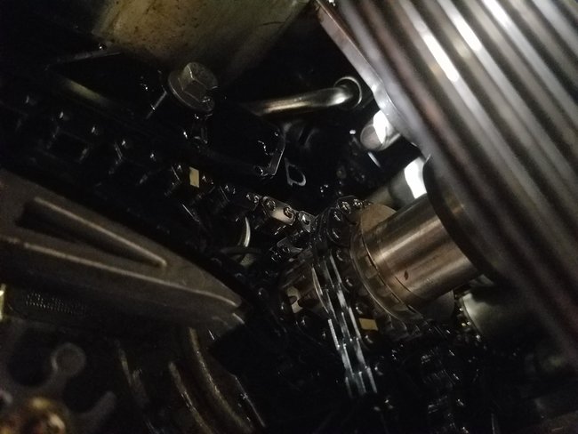
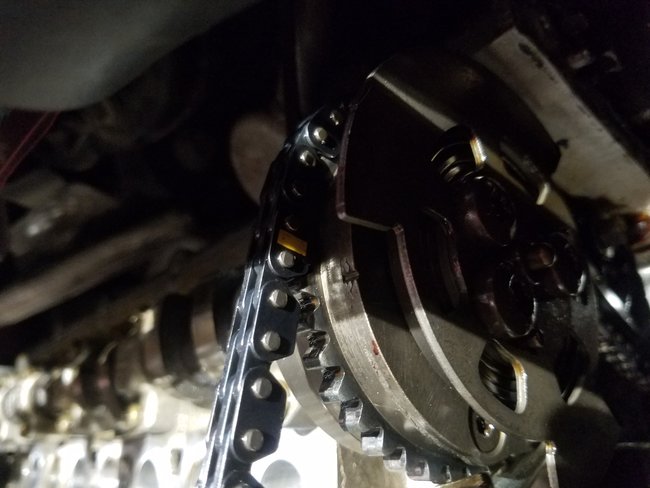
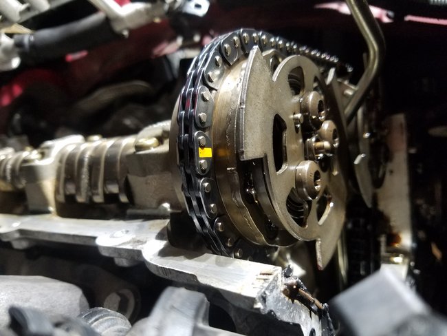
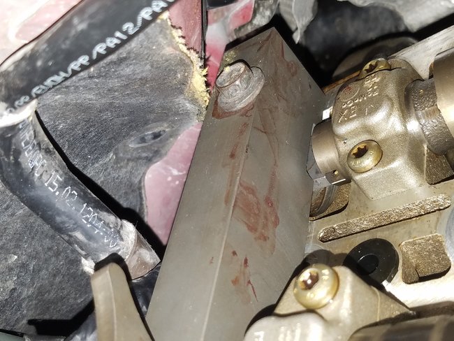
Here are the diagrams you will need to replace the timing chain and guides with the tension-er's. (Below)

Please let us know if you need anything else to get the problem fixed.

Cheers, Ken
Was this
answer
helpful?
Yes
No
+1
Wednesday, June 20th, 2018 AT 12:04 PM
Tiny
MARK FRIZZELL
  • MEMBER
  • 141 POSTS
Great, I have everything and have studied everything you gave plus everything I could find on the web (not much on there). Lol
I have valve covers off, etc.
My question is, as far as I can tell there is only one way everything lines up? In other words there is no 180 off or anything like that right?
Was this
answer
helpful?
Yes
No
+1
Tuesday, July 24th, 2018 AT 1:33 PM
Tiny
MARK FRIZZELL
  • MEMBER
  • 141 POSTS
Actually I mean 360 off.
Was this
answer
helpful?
Yes
No
+1
Tuesday, July 24th, 2018 AT 1:34 PM
Tiny
MARK FRIZZELL
  • MEMBER
  • 141 POSTS
I notice that as I rotate engine the marks on the old factory chain never line up, is this because of the VVT?
Was this
answer
helpful?
Yes
No
+1
Wednesday, July 25th, 2018 AT 8:35 AM
Tiny
KEN L
  • MASTER CERTIFIED MECHANIC
  • 42,961 POSTS
Correct you must bottom out the VVT to set the timing in the guides above they have you remove the camshaft angle sensor but I think you can do it without the special tool. Just make sure the camshaft actuators are all the way back (not advanced).

Let us know what happens and please upload pictures or videos of the problem.

Cheers, Ken
Was this
answer
helpful?
Yes
No
+1
Wednesday, July 25th, 2018 AT 2:13 PM
Tiny
MARK FRIZZELL
  • MEMBER
  • 141 POSTS
Yeah, that is what I thought. I have the tool for VVT's, I assume the engine rotation is clockwise as your looking at the front of crank, and VVT set all the way back would be counter clockwise.
Was this
answer
helpful?
Yes
No
+1
Wednesday, July 25th, 2018 AT 2:38 PM
Tiny
STEVE W.
  • MECHANIC
  • 13,002 POSTS
Yes, on the rotation directions you have.
Was this
answer
helpful?
Yes
No
+1
Sunday, July 29th, 2018 AT 8:06 AM
Tiny
MARK FRIZZELL
  • MEMBER
  • 141 POSTS
Okay Ken, things are looking good except when I pulled pin on one tension-er then reset it, it will not spring back out? What happened?
Was this
answer
helpful?
Yes
No
Monday, July 30th, 2018 AT 12:56 PM
Tiny
MARK FRIZZELL
  • MEMBER
  • 141 POSTS
Sorry I got it, was not holding my tongue out. Lol
Was this
answer
helpful?
Yes
No
Monday, July 30th, 2018 AT 2:34 PM
Tiny
MARK FRIZZELL
  • MEMBER
  • 141 POSTS
I noticed after get all together, removed the cam holding tool from back of cam on left bank that the cams moved a little bit. Normal?
Was this
answer
helpful?
Yes
No
Monday, July 30th, 2018 AT 3:03 PM
Tiny
STEVE W.
  • MECHANIC
  • 13,002 POSTS
A small amount is okay, like 1/2 a link or less. More than that double check that the marks are okay. If they are still lined up you should be good.
Was this
answer
helpful?
Yes
No
+1
Monday, July 30th, 2018 AT 5:08 PM
Tiny
MARK FRIZZELL
  • MEMBER
  • 141 POSTS
Picture of left bank.
Was this
answer
helpful?
Yes
No
Tuesday, July 31st, 2018 AT 7:23 AM
Tiny
MARK FRIZZELL
  • MEMBER
  • 141 POSTS
I notice when put the cam tool back on the exhaust cam is just slightly off, not much just a shade enough tool will not go fully in. I really need to get this right real pain to disassemble. Lol
Was this
answer
helpful?
Yes
No
Tuesday, July 31st, 2018 AT 7:33 AM
Tiny
KEN L
  • MASTER CERTIFIED MECHANIC
  • 42,961 POSTS
Yes, if the cam tool is on the engine when these images were taking the chain looks like it is off one tooth or the actuator is not fully backed off. Can you send pictures of the cam tool installed?
Was this
answer
helpful?
Yes
No
+1
Tuesday, July 31st, 2018 AT 11:31 AM
Tiny
MARK FRIZZELL
  • MEMBER
  • 141 POSTS
I could not get cam tool back on the exhaust cam is turned slightly so will not lineup. So guess I should start over.
Was this
answer
helpful?
Yes
No
Tuesday, July 31st, 2018 AT 11:56 AM
Tiny
MARK FRIZZELL
  • MEMBER
  • 141 POSTS
The pictures were after I used the actuator tool to tension the chains counter clockwise by the intake cam then removed the cam holding tool went. Back to check and look like the exhaust cam rotated slightly, the cam holder won't got back on. So I should start over?
Was this
answer
helpful?
Yes
No
Tuesday, July 31st, 2018 AT 12:02 PM
Tiny
MARK FRIZZELL
  • MEMBER
  • 141 POSTS
And yes that is my blood on the tool. Lol. Is in on the intake side, not on exhaust. No the previous pictures were after the tool was removed.
Was this
answer
helpful?
Yes
No
Tuesday, July 31st, 2018 AT 12:44 PM
Tiny
MARK FRIZZELL
  • MEMBER
  • 141 POSTS
I redid the left bank, this were it is, tool in back fully seated, chain and tension-er on. I have not yet put tension on actuators yet.
Was this
answer
helpful?
Yes
No
+1
Wednesday, August 1st, 2018 AT 9:25 AM
Tiny
KEN L
  • MASTER CERTIFIED MECHANIC
  • 42,961 POSTS
Looks good from here. Are the crankshaft marks lined up you are on TDC? If so it looks good to me. Sorry about the injury.
Was this
answer
helpful?
Yes
No
+1
Wednesday, August 1st, 2018 AT 11:40 AM
Tiny
MARK FRIZZELL
  • MEMBER
  • 141 POSTS
Yep, crank at 6:00 o'clock, have not put tension on actuators yet.
Was this
answer
helpful?
Yes
No
Wednesday, August 1st, 2018 AT 11:46 AM

Please login or register to post a reply.

Sponsored links