Welcome to 2CarPros.
If you have white smoke from the exhaust and are using coolant, there is a very good chance the head gasket has failed. When this happens, it can allow coolant to enter the engine's combustion chamber and when it is burned with the fuel, it puts off an odor and white smoke.
Here is a link that explains how to check for a bad head gasket. Take a look through it and see if anything mirrors what you are experiencing.
https://www.2carpros.com/articles/head-gasket-blown-test
As far as the shift, it could be related with an overheating issue. Since you are losing coolant, it may be an issue.
_______________________________________________________
If you determine it is a head gasket, here are the directions for removal and replacement of the cylinder head. Of course, once removed, a new gasket is installed. This is a very big job on this vehicle. However, I will help if needed.
All attached pictures correlate with the directions.
_______________________________________________________
2001 Saturn SL2 L4-1.9L DOHC VIN 7
Cylinder Head Removal
Vehicle Engine, Cooling and Exhaust Engine Cylinder Head Assembly Service and Repair Procedures Cylinder Head Removal
CYLINDER HEAD REMOVAL
- Tools Required
- SA9124E Regulator Valve Remover/Replacer
- J-43223 Rocker Arm Removal Tool
- J-43299 Camshaft Holder
- SA9lllE Mubea Hose Clamp Pliers
- SA9104E Front Crank Seal Replacer
- SA9123E Gasket Seal Cutter
pic 1
CAUTION: DO NOT ALLOW SMOKING OR THE USE OF OPEN FLAMES IN THE AREA WHERE WORK ON THE FUEL SYSTEM IS TAKING PLACE. ANY TIME THE FUEL SYSTEM IS BEING WORKED ON, DISCONNECT THE NEGATIVE BATTERY CABLE, EXCEPT FOR THOSE TESTS WHERE BATTERY VOLTAGE IS REQUIRED.
IMPORTANT: Camshaft(s) can be removed using service tool J-43299. Gauge bar kit SA9127E is used for pressurizing the cylinder with 690 kPa (100 psi) of air to hold the valves closed. Valve springs, caps and stem seals can be replaced without removing the cylinder head using service tool SA9124E. Rocker arm assemblies can be removed using tool J-43223. (Refer to "Camshaft and Lifter Replacement" and "Valve Spring and Stem Seal Replacement In-Vehicle".)
pic 2
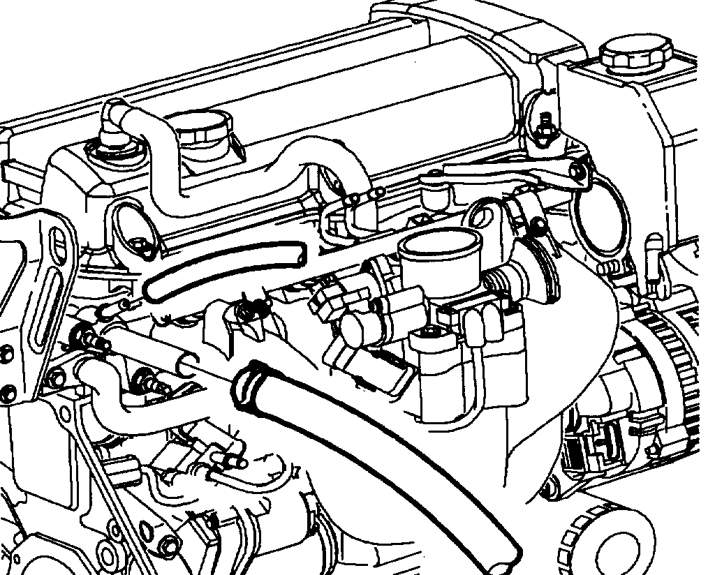
1. Disconnect cable from negative terminal of battery and remove coolant bottle cap.
NOTICE: The engine's cooling system thermostat will not function correctly once it has been contacted by oil. If oil is found in the cooling system, it must be flushed and the thermostat's cartridge replaced.
pic 3
2. Drain coolant from radiator and engine. (Engine drain is at right front corner of engine block under thermostat housing.)
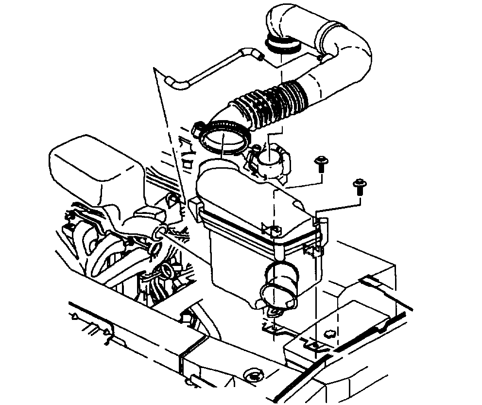
3. Remove air cleaner cover assembly and air inlet duct.
a. Disconnect the cam cover air hose at air duct.
pic 4
4. Disconnect accelerator cable from throttle body and intake manifold bracket.
IMPORTANT: The throttle body assembly, fuel rail, injectors and intake manifold can be removed with cylinder head assembly from vehicle.
pic 5
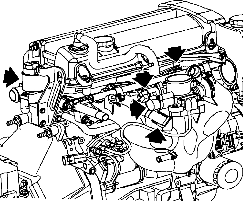
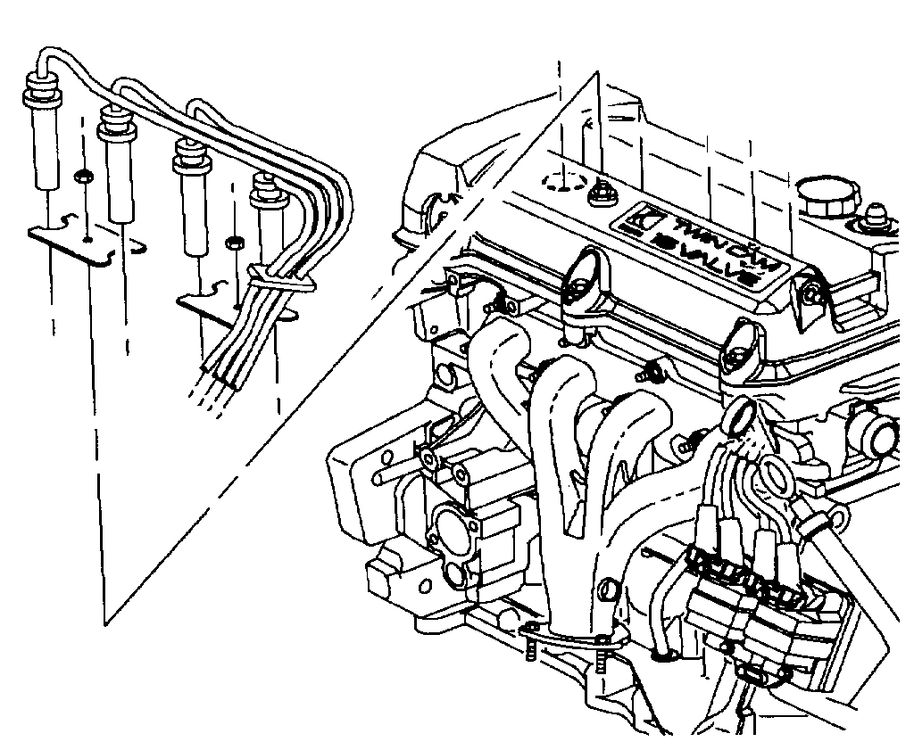
5. Remove the following electrical connectors:
a. Coolant temperature gauge and Powertrain Control Module (PCM) connector located at rear side of head.
IMPORTANT: Use long nose pliers to remove the coolant temperature connectors.
b. Injector connector
c. Idle Air Control (IAC) valve
d. Throttle Position (TP) sensor
e. Manifold Air Pressure (MAP)
pic 6
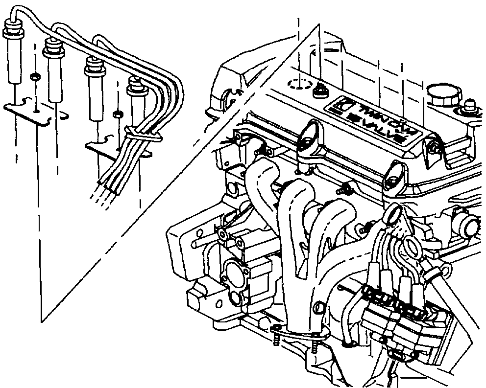
f. Remove oxygen sensor
g. Remove spark wires
h. Air conditioner compressor
i. EGR
pic 7
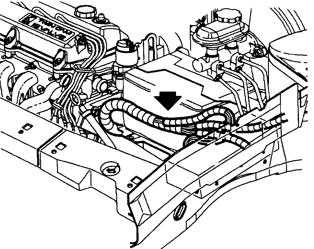
6. Lay harness over onto underhood junction block and battery cover.
pic 8
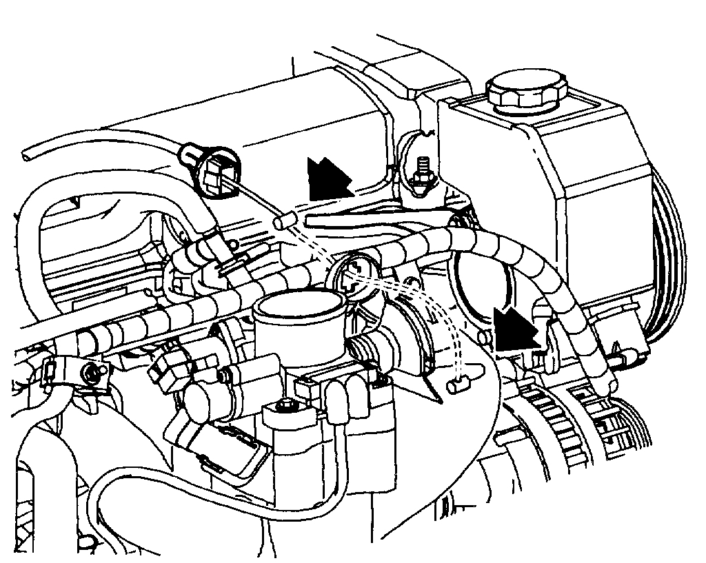
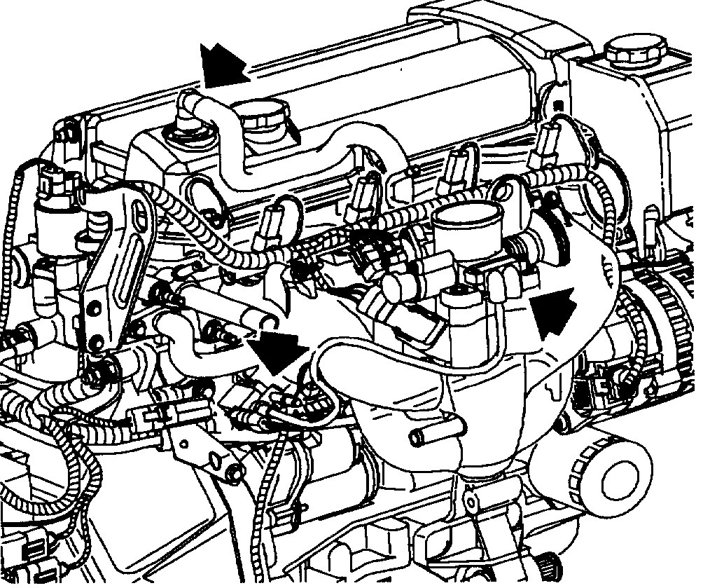
7. Disconnect the following vacuum hoses:
a. EVAP canister purge valve
b. PCV hose at cam cover
c. Throttle body connector
d. Vacuum brake booster hose at brake booster.
IMPORTANT: The MAP sensor does not require removal.
pic 9
8. Disconnect the following hoses:
a. Upper radiator hose at cylinder head outlet.
b. Deaeration hose at intake manifold.
c. Heater hose at intake manifold or front of dash.
IMPORTANT: Use service tool SA911E (Snap-on Tool HPC10 or equivalent) to remove hose clamps.
CAUTION: CATCH LEAKING FUEL IN A CONTAINER WHENEVER FITTINGS ARE LOOSENED OR LINES ARE DISCONNECTED.
pic 10
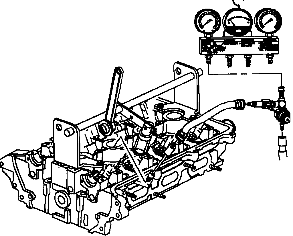
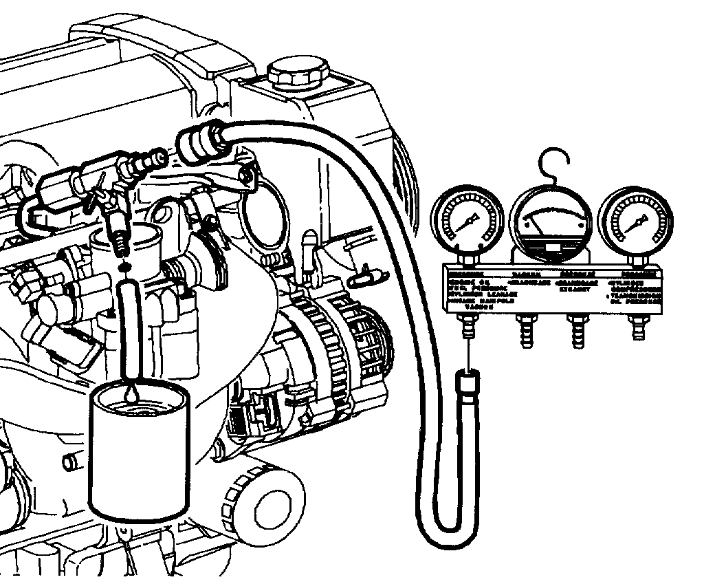
9. Disconnect fuel line:
a. Fuel pressure can be bled in to an approved container using gauge bar kit SA9127E.
b. Remove attachment bolt that clamps fuel lines to the intake manifold support brace.
c. Disconnect the fuel supply line to the fuel rail.
d. Remove power steering support bracket.
pic 11
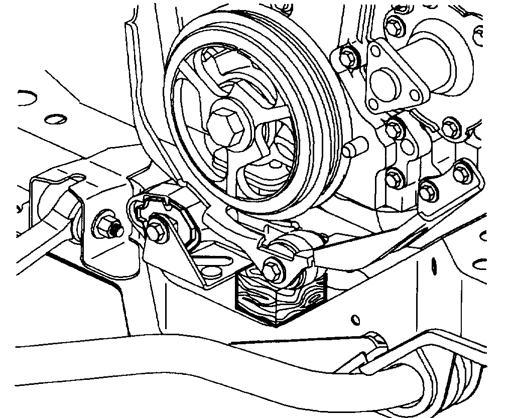
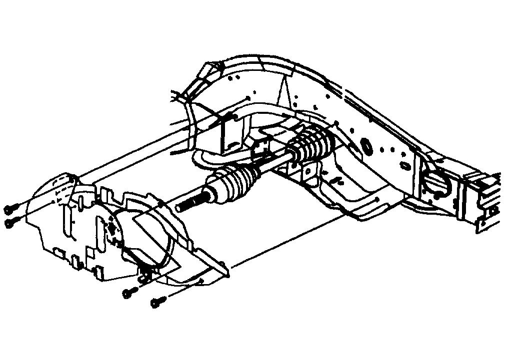
10. Unclip the lower splash shield attachments and place a 1 inch x 1 inch x 2 inch long block of wood between the torque strut and cradle.
IMPORTANT: Installation of the wood block prior to upper engine torque axis mount removal allows the mount to be easily installed without lifting or jacking the powertrain.
pic 12
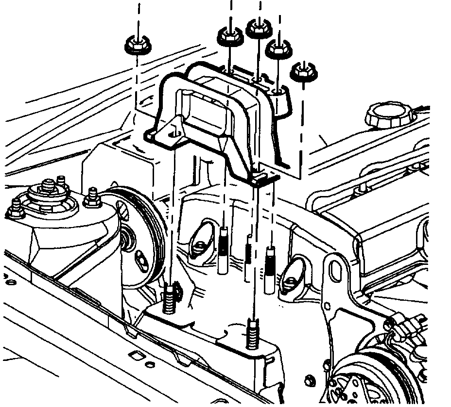
11. Remove the three right-hand, upper engine torque axis mount to front cover nuts and the two mount to midrail bracket nuts, allowing the powertrain to rest on the block of wood.
pic 13
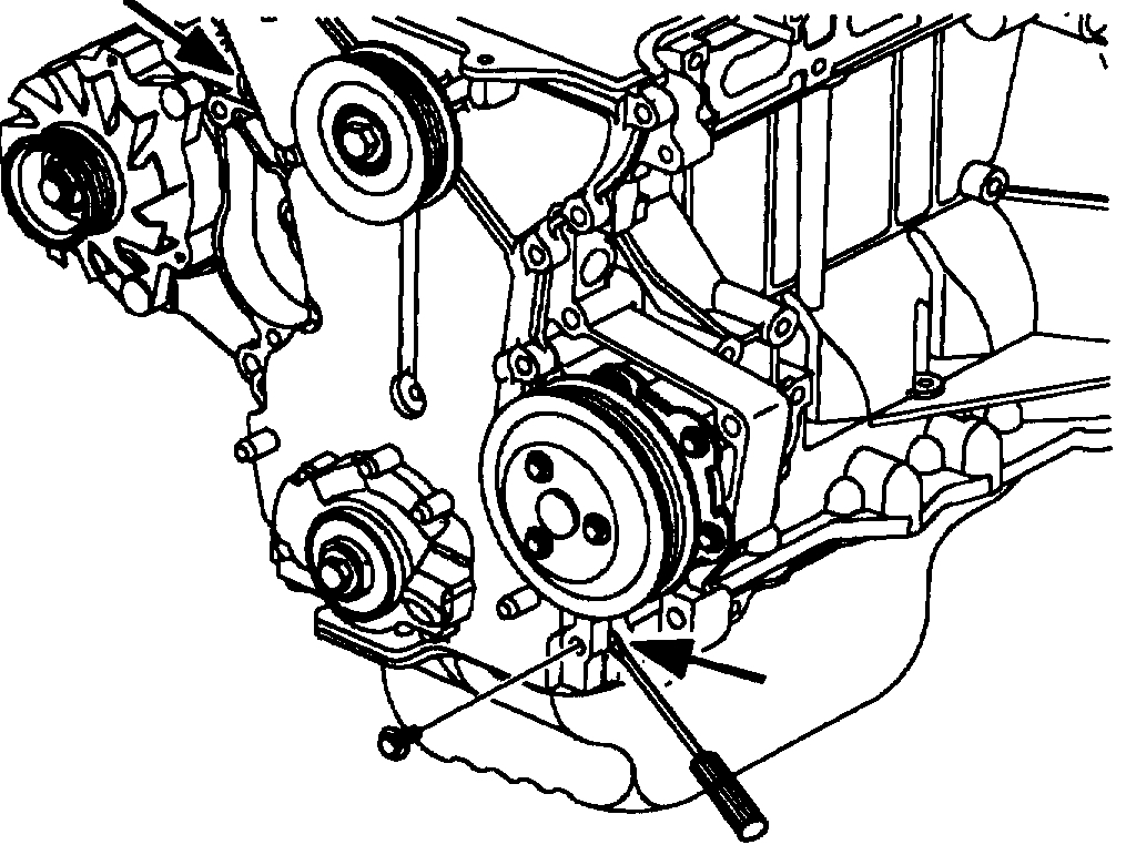
12. Remove the accessory drive belt and tensioner. It is not necessary to remove the water pump pulley.
IMPORTANT: The accessory drive belt idler pulley must be removed to allow the front cover to be removed and replaced in the vehicle.
13. Remove camshaft cover assembly.
IMPORTANT:
- Cover camshaft area whenever repairs are not being performed to prevent foreign debris from entering engine.
- Inspect the 8 cam cover silicone isolators for cracks. Replace the isolators if deterioration exists.
pic 14
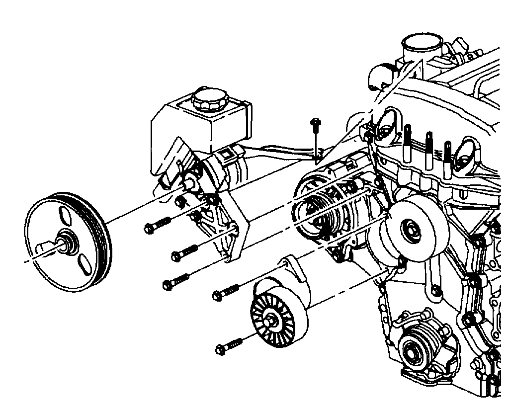
14. Remove the five power steering pump bracket attachment bolts (if equipped) and position the pump next to the right-hand front of dash panel, away from the cylinder head and intake manifold.
IMPORTANT: It is not necessary to remove the water pump pulley.
pic 15
15. Remove the three A/C compressor front bracket bolts (if equipped) attached to cylinder head and block. The rear bracket bolts can be removed from the compressor or bracket attachment to block and head.
IMPORTANT:
- The rear compressor bracket center hole is slotted for ease of compressor removal and installation.
- It is not necessary to discharge the A/C system.
a. Tie the compressor assembly to the vehicle front support bar.
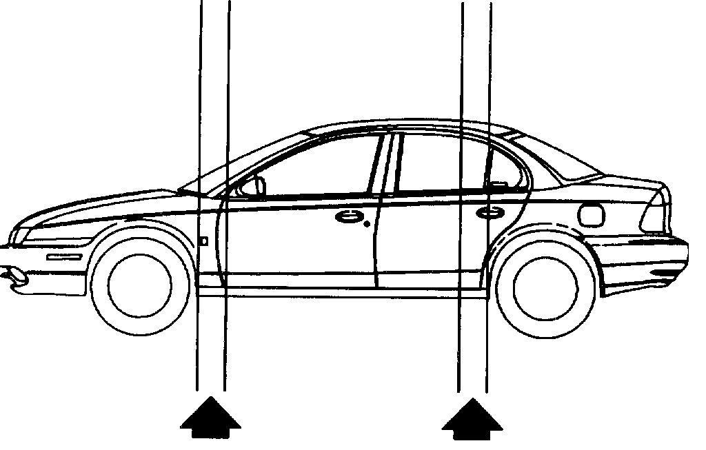
CAUTION: MAKE SURE THE VEHICLE IS PROPERLY SUPPORTED AND SQUARELY POSITIONED PRIOR TO LIFTING. TO HELP AVOID PERSONAL INJURY WHEN A VEHICLE IS ON A HOIST, PROVIDE ADDITIONAL SUPPORT FOR THE VEHICLE ON THE OPPOSITE END FROM WHICH COMPONENTS ARE TO BE REMOVED. MAKE SURE THE HOIST DOES NOT CONTACT FUEL OR BRAKE LINES.
pic 16
16. Jack or raise the vehicle on a hoist.
17. Drain engine oil.
pic 17
18. Remove the right wheel and splash shield.
pic 18
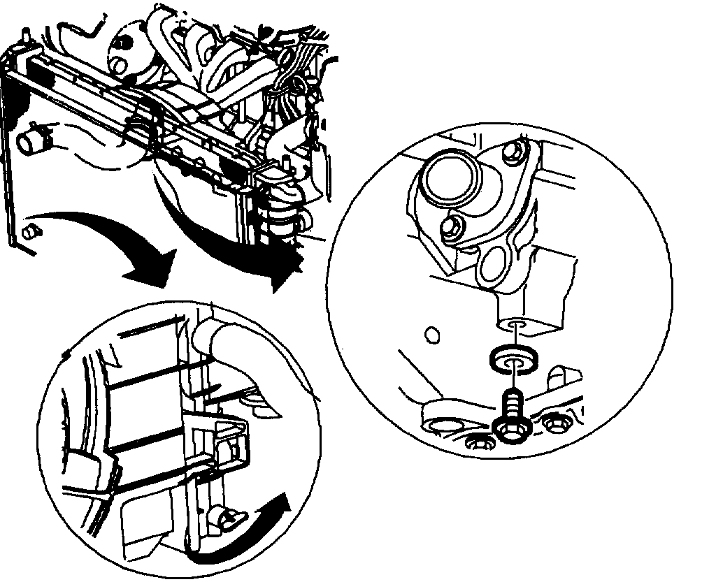
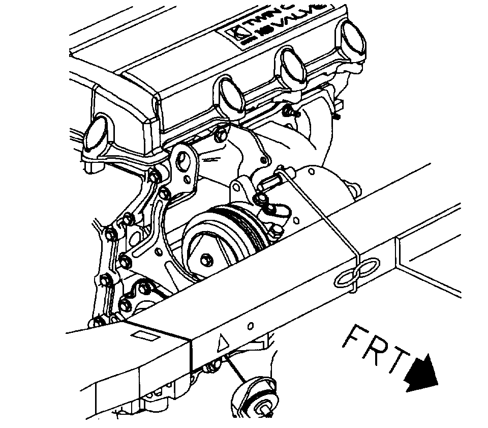
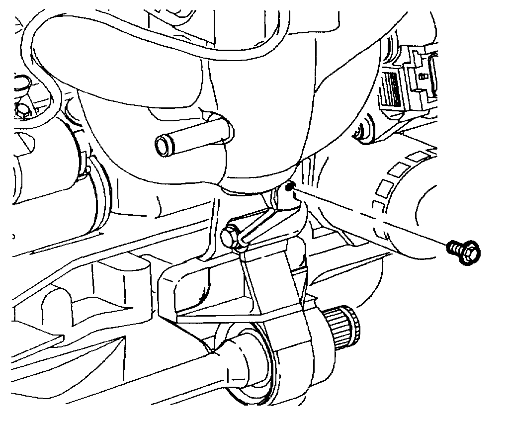
19. Remove the intake manifold support brace bolt attached to the intake manifold located next to the generator.
pic 19
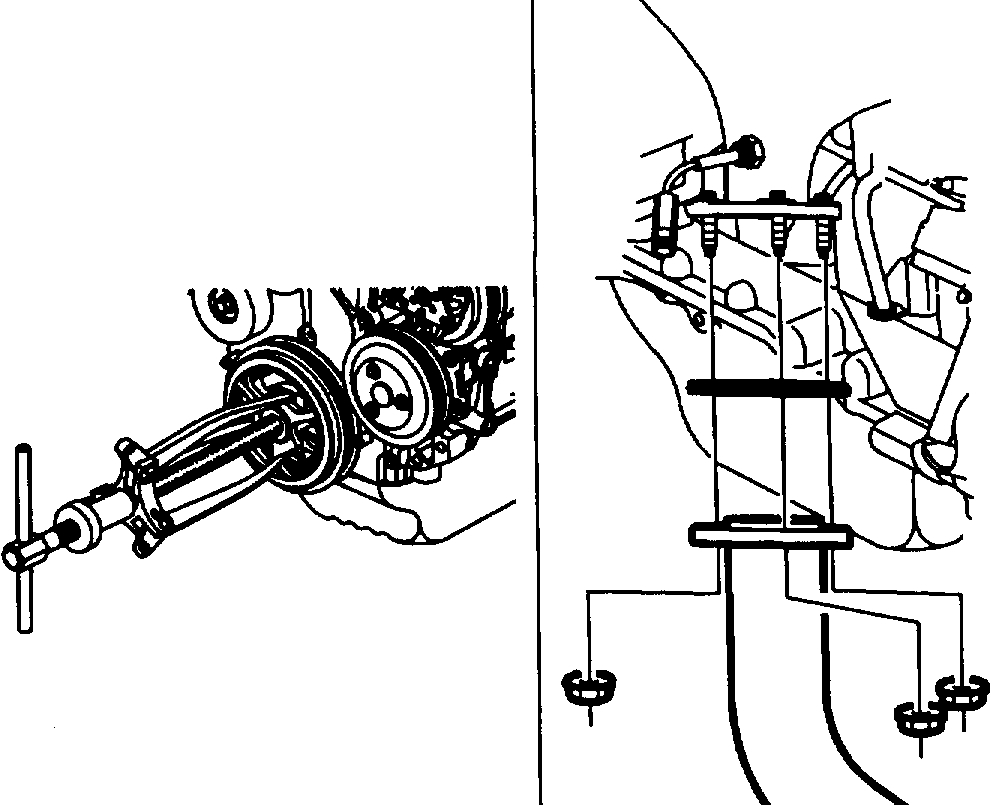
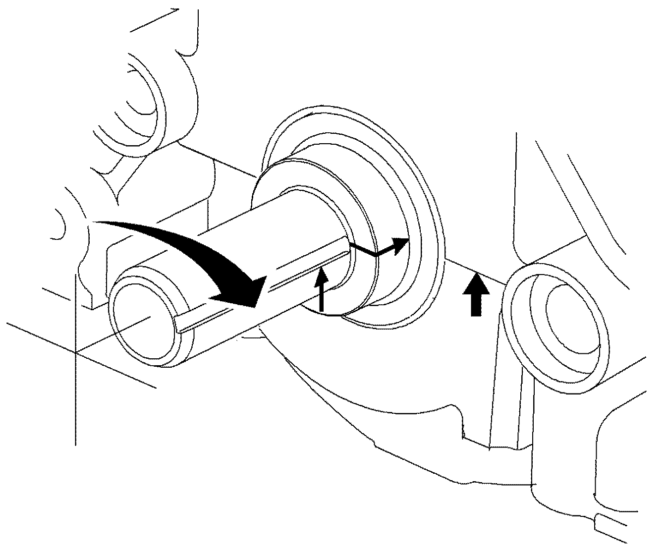
20. Remove front damper/pulley assembly. Hold damper with a strap wrench or use a 3/4 inch square x 12 inch long piece of wood wedged between the damper spoke and rear, lower side of front cover when removing the bolt.
a. Puller jaw slots are cast into damper/pulley assembly for removal with a small three jaw puller if required.
21. Disconnect exhaust pipe from exhaust manifold:
a. Remove the three nuts from the flange.
pic 20
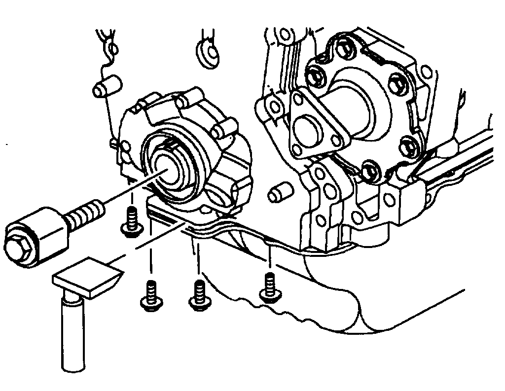
22. Removal of the front cover assembly:
a. Install the crankshaft gear retaining service tool SA9104E to make sure the front crankshaft timing sprocket is held firmly in place.
IMPORTANT: Install service tool SA9104E with flat side toward the sprocket. Failure to hold the crankshaft timing sprocket in place will cause timing chain guide damage. This tool also aligns the oil pump gerotor during front cover installation. After the front cover assembly is loosened and moved approximately 25.4 mm (1 inch) from the engine, the crankshaft timing gear service tool should be removed.
b. Remove the four front oil pan bolts.
c. Use RTV cutter service tool SA9123E to cut the oil pan seal away from front cover.
d. Spray the two dowel pin holes (upper left-hand and lower right-hand side of cover) in the cover with penetrating oil to facilitate cover removal off the dowel pins.
e. Remove the front cover bolts.
IMPORTANT: One front cover assembly attachment bolt is located under the torque axis mount flange, above the accessory drive belt pulley.
pic 21
f. Using a screwdriver, pry the front cover away from the cylinder block using the pry locations tabs provided.
IMPORTANT:
- The front cover assembly can be removed from under the hood or through the wheel well.
- Cover the front of the engine with a shop towel to prevent debris entry into oil gallery openings and pan.
NOTICE: Position crankshaft 90 degrees off top dead center to make sure pistons will not contact valves upon assembly.
pic 22
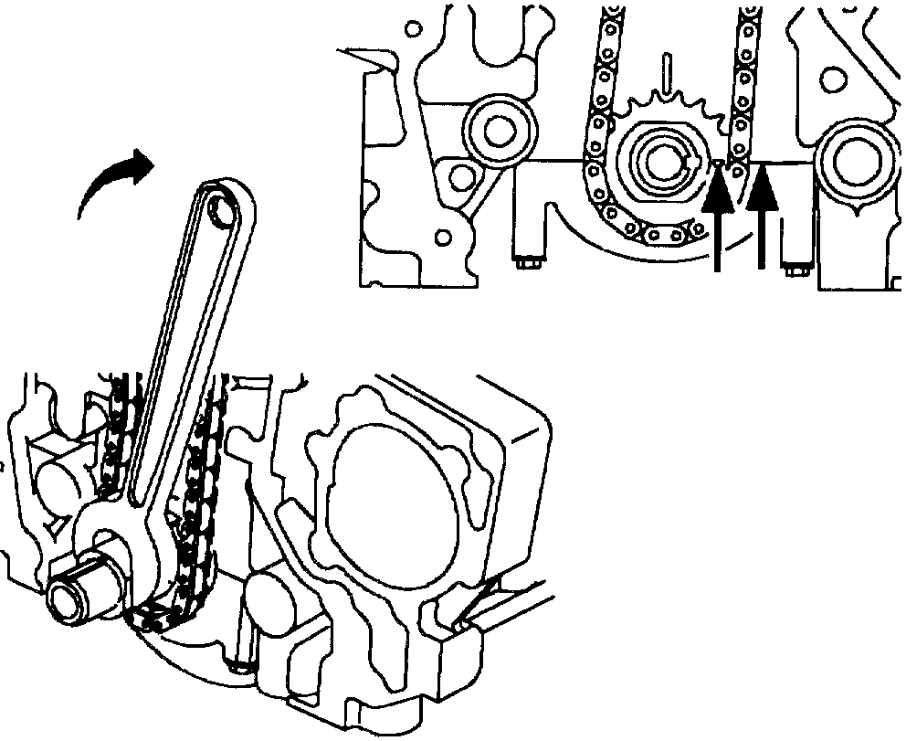
23. Rotate crankshaft clockwise (viewed from crankshaft accessory belt end) so timing mark on crankshaft sprocket and key way align with main bearing cap split line.
CAUTION: THE CAMSHAFTS CAN ROTATE DURING TIMING CHAIN AND SPROCKET REMOVAL. DO NOT PLACE FINGERS OR TOOLS BETWEEN THE CAMSHAFT SPROCKET AND CHAIN DURING REMOVAL OR ASSEMBLY.
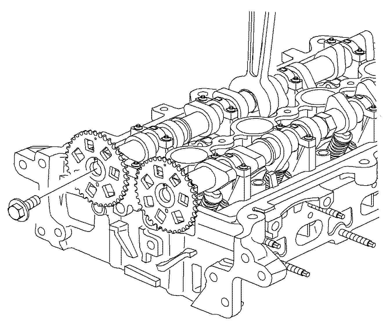
pic 23
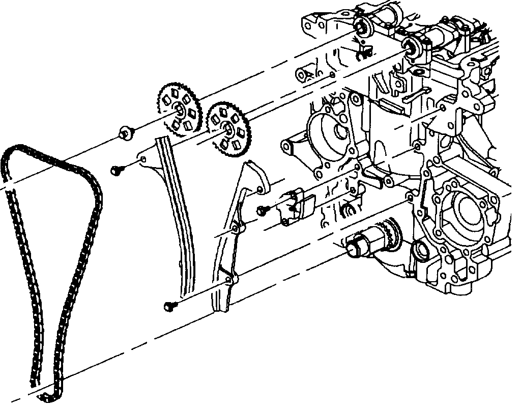
24. Remove timing chain tensioner, guides, camshaft sprockets and chain. Use a 24 mm wrench to hold the camshaft when removing the sprocket bolts.
IMPORTANT: Camshaft bearing caps are marked for proper installation.
pic 24
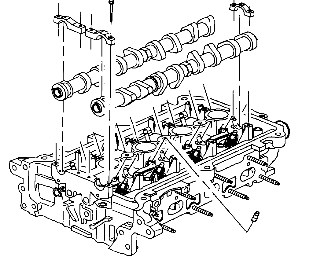
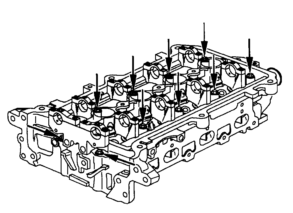
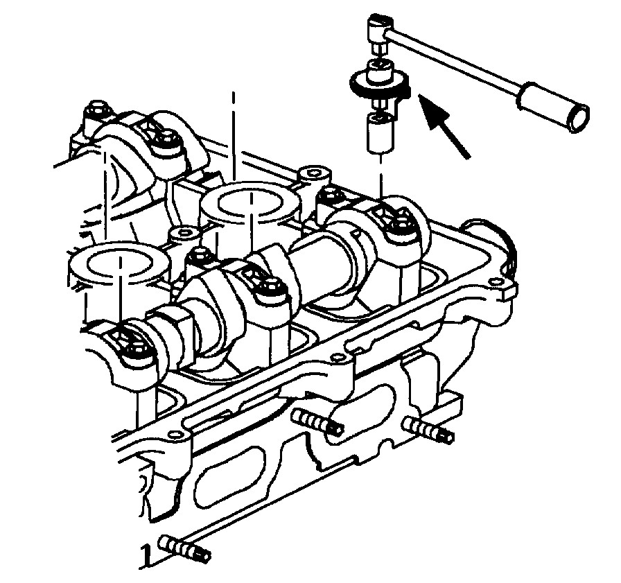
25. Uniformly remove camshaft bearing cap attachment bolts and caps.
26. Remove each camshaft.
27. Remove lash adjuster and rocker arms. Keep them in order.
NOTICE: Use only a six point socket to remove the cylinder head bolts. A 12 point socket will round off the bolt head.
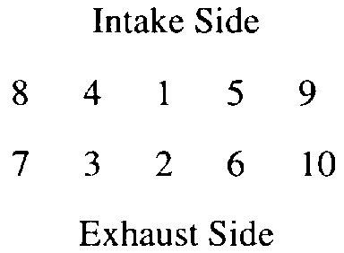
pic 25
Intake side
3 7 10 6 2
4 8 9 5 1
Exhaust side
28. Uniformly loosen and remove the 10 head bolts in several passes, in the sequence shown.
IMPORTANT: Head warpage or cracking could result from removing the bolts out of order or when cylinder is hot.
NOTICE: Be careful not to damage the aluminum cylinder head and block gasket sealing surface when removing the cylinder head or during cleaning.
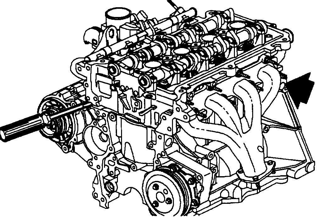
pic 26
29. Lift the cylinder head from the dowels on the cylinder block and place the head on wooden blocks or a bench. If the cylinder head is difficult to lift off, pry with a screwdriver between the cylinder head and block bosses.
______________________________
Install
2001 Saturn SL2 L4-1.9L DOHC VIN 7
Cylinder Head Installation
Vehicle Engine, Cooling and Exhaust Engine Cylinder Head Assembly Service and Repair Procedures Cylinder Head Installation
CYLINDER HEAD INSTALLATION
CYLINDER HEAD INSTALLATION (DOHC)
TOOLS REQUIRED:
- SA91101NE Feeler Gage Set
- SA9140E Torque Angle Gage
- SA9177NE Straight Edge 24"
- SA9179NE Dial Indicator
pic 27
1. Remove the gasket material:
a. Using a plastic or wood gasket scraper, remove all the gasket material from the cylinder block surface.
b. Clean the cylinder block bolt holes of any residual sealer, oil, or foreign material. Remove any oil with solvent.
c. Clean the cylinder head bolt threads with a wire brush.
d. Coat the bolt threads with engine oil.
e. Inspect cylinder block orifice for any debris.
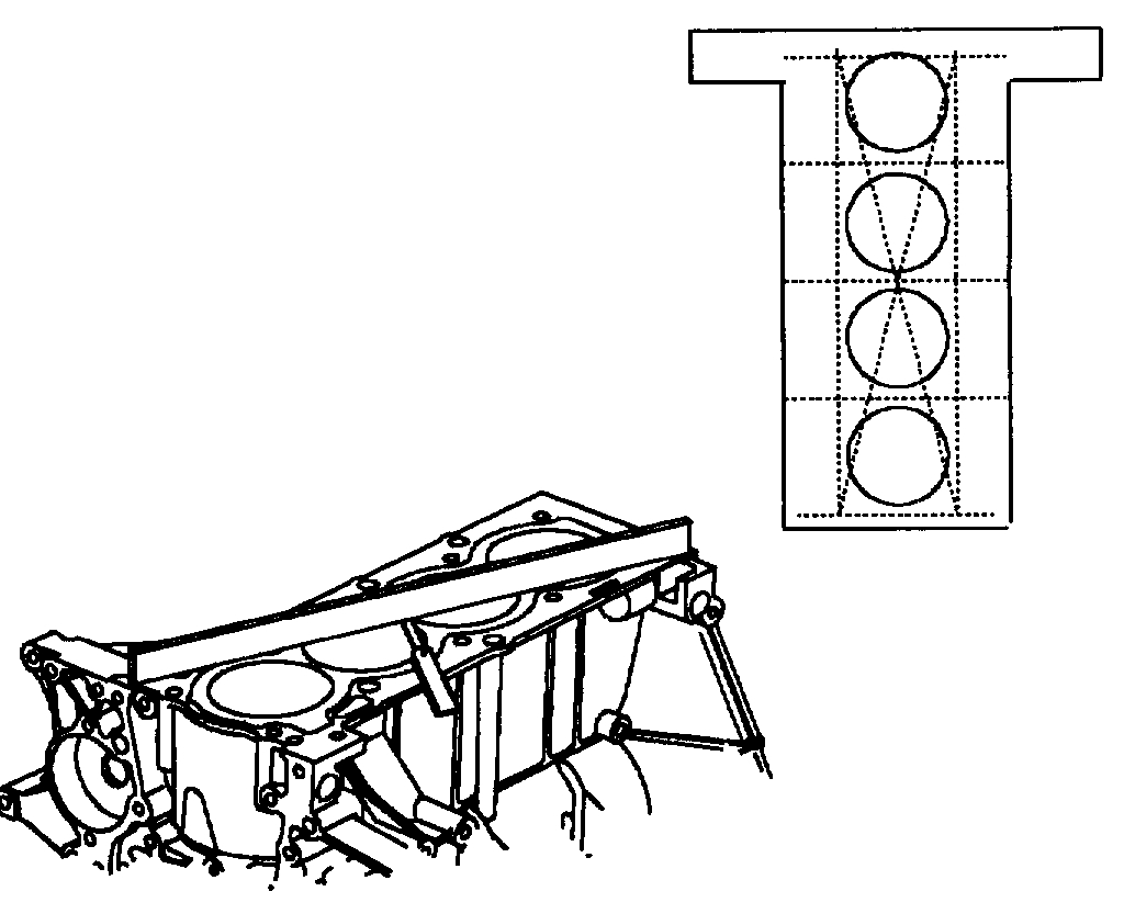
pic 28
NOTICE: Be careful not to scratch or score the cylinder block and head aluminum surfaces when cleaning.
2. Inspect the top of the cylinder block for flatness. Using a SA9177NE or equivalent and a SA91101NE or equivalent, measure the surfaces contacting the cylinder head gasket for warpage.
MAXIMUM WARPAGE
TRANSVERSE
Standard: 0.03 mm (0.0012 in.)
Service Limit: 0.05 mm (0.002 in.) max.
LONGITUDINAL
Standard: 0.07 mm (0.0028 in.)
Service Limit: 0.1 mm (0.004 in.)
pic 29
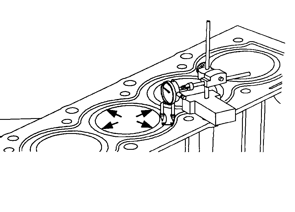
3. Inspect the liner height at 4 locations around the cylinder bore using a SA9179NE or equivalent.
LINER HEIGHT
STANDARD: FLUSH
Service Limit: 0.013 mm (0.0005 in.) max.
pic 30
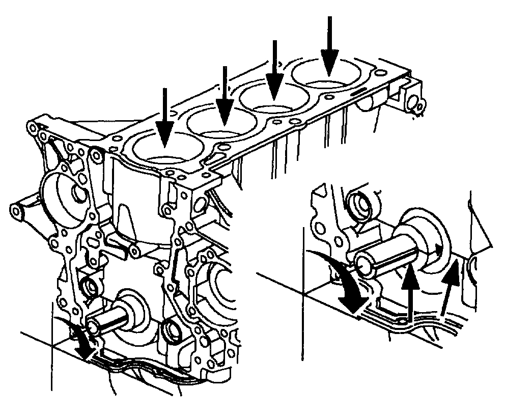
4. Inspect the cylinder bore and the tops of pistons for debris, deep scratches, excessive carbon built up, etc.
NOTICE: The crankshaft must be correctly positioned to prevent valve and piston damage. Dowel pins in each camshaft must be located at the 12 o'clock position.
5. Position the number one cylinder, clockwise as viewed from the accessory drive end 90 degrees past top dead center (TDC). The crankshaft is correctly positioned when the crankshaft keyway and sprocket timing mark are aligned with the cylinder block main bearing cap split line.
IMPORTANT: Whenever a cylinder block or head bolts are replaced, install the cylinder head and torque the bolts to 65 Nm (48 lbs ft). Next, remove the bolts, coat the threads with engine oil and follow the torque angle procedure steps. Torquing the bolts one time prior to following the torque angle steps insures proper clamp load is achieved.
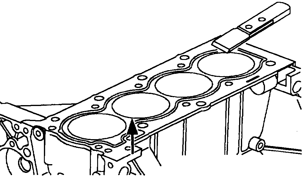
pic 31
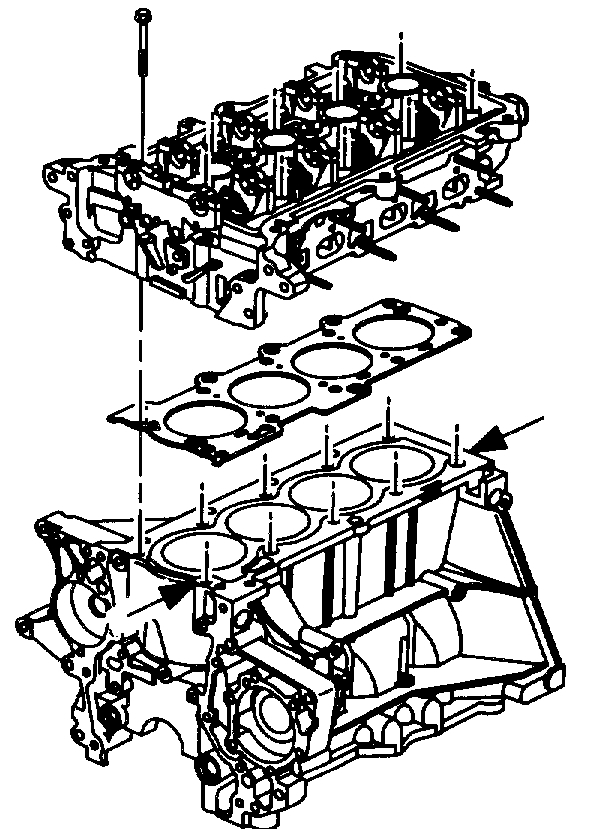
6. Install a new cylinder head gasket.
7. Install the cylinder head, aligning it on the dowels.
a. Carefully guide the head into place.
b. Thread the bolts, threads coated with engine oil in by hand until finger tight.
pic 32
IMPORTANT: The following steps must be completed in sequence. This will ensure uniform bolt tension.
8. Cylinder head bolt tightening procedure:
9. In sequence, torque the cylinder head bolts.
TIGHTEN
Cylinder head bolts - first pass to 30 Nm (22 lb. ft.).
pic 33
10. In sequence, torque all bolts, second pass.
TIGHTEN
Cylinder head bolts - second pass (DOHC to ) 45 Nm (33 lb. ft.) + 90 degrees.
11. Install the SA9140E or equivalent, Snap-on Tool 360.
12. Calibrate the gage to zero.
13. In sequence, turn each bolt an additional 90 degrees - final pass.
______________________________________
You will need to retime the engine, so here are the directions for installing the timing chain. If it has never been replaced, this is a good time to install a new chain and components.
______________________________________
2001 Saturn SL2 L4-1.9L DOHC VIN 7
Timing Chain, Sprockets, Guides and Tensioner Installation
Vehicle Engine, Cooling and Exhaust Engine Timing Components Timing Chain Service and Repair Procedures Timing Chain, Sprockets, Guides and Tensioner Installation
TIMING CHAIN, SPROCKETS, GUIDES AND TENSIONER INSTALLATION
Camshaft Timing Chain, Sprocket, and Tensioner (DOHC)
Assemble the timing chain, the sprockets, the guides and the tensioners:
pic 34
1. Verify that the crankshaft is positioned at 90 degrees past top dead center (TDC). The crankshaft keyway and sprocket must be aligned with the cylinder block main bearing cap split line, as viewed from the accessory drive end, to prevent piston and valve damage.
pic 35
Notice: Do not torque the camshaft retaining bolts against the 3/16 in. timing pins as it will damage the cylinder head.
2. Install the camshaft timing gears, the retaining bolts and washers. The letters FRT on the sprockets must face forward, away from the cylinder head. Wrench flats 24 mm are provided to hold the camshafts from rotating while torquing the bolts.
Tighten
Tighten the camshaft sprockets-to-camshafts to 100 N.m (74 lb ft).
pic 36
3. Bring the camshafts up to the number one TDC by rotating the camshaft and sprocket until the timing pins 4.77 mm (3/16 in) drill can be installed. Wrench flats are installed on the camshafts to assist with rotation.
pic 37
4. Rotate the crankshaft counterclockwise, as viewed from the accessory drive end, until the number one cylinder is TDC. The crankshaft sprocket timing mark will align with cylinder block timing mark.
pic 38
Caution: The camshaft can rotate during timing chain installation when the timing pins (4.77 mm (3/16 in) drill) have not been installed. Do not place fingers between the camshaft sprockets and the chain during the timing chain installation.
5. Place the timing chain over the camshaft sprockets and under the crankshaft sprocket.
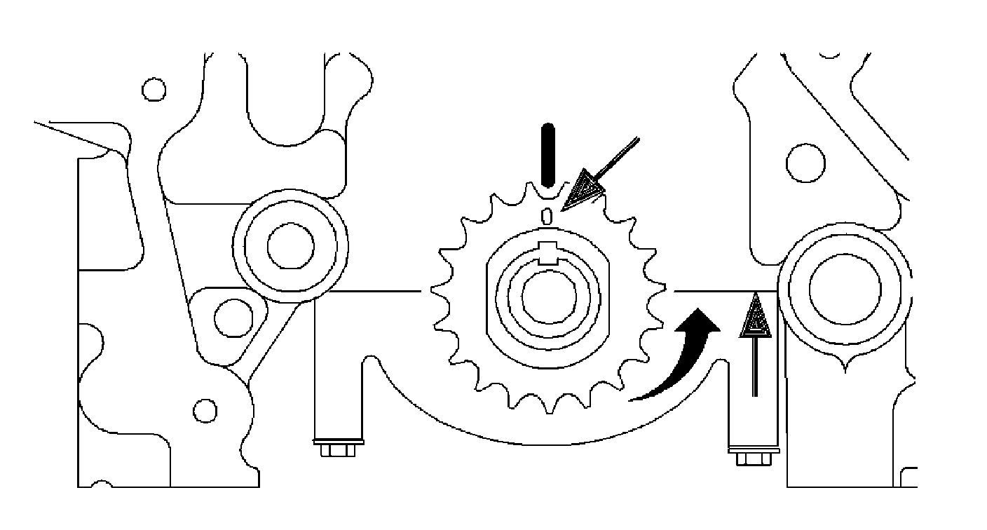
pic 39
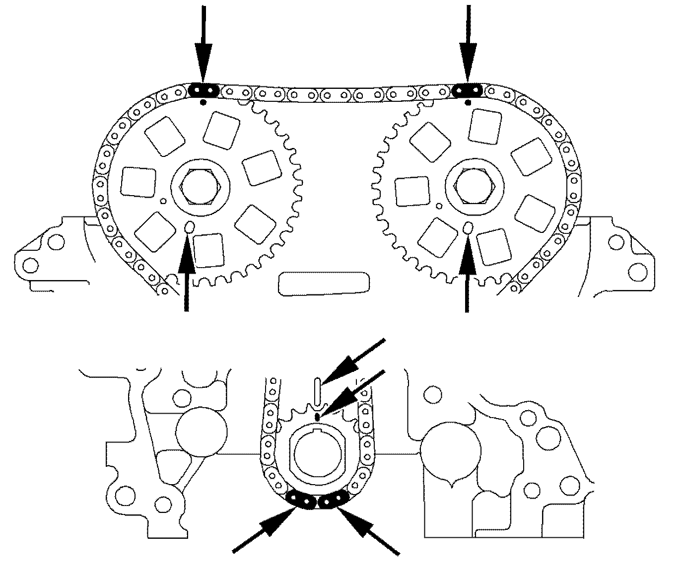
Notice: Excess slack in the chain must be kept to the chain tensioner side (movable guide) of the cylinder block when installing the timing chain or the camshaft sprockets will not be correctly timed to the crankshaft sprocket.
Important: Two separated black link plates align the pip marks on the camshaft sprockets and another 2 paired link plates align the crankshaft sprocket tooth that is located at the six o'clock position. The pip mark on the crankshaft sprocket must be aligned with the timing mark on the cylinder block.
Important: Alignment of both timing pin holes, crankshaft sprocket pip mark with cylinder block mark, black links with camshaft and crankshaft sprockets must be correct to make sure the engine is properly timed.
6. Ensure that the black colored link plates are located over the pip mark on the cam sprockets only. The crankshaft sprocket tooth must be pointed directly downward at the 6 o'clock position between the 2 silver colored links. The pip mark on the crankshaft sprocket will be aligned with the timing mark on the cylinder block.
pic 40
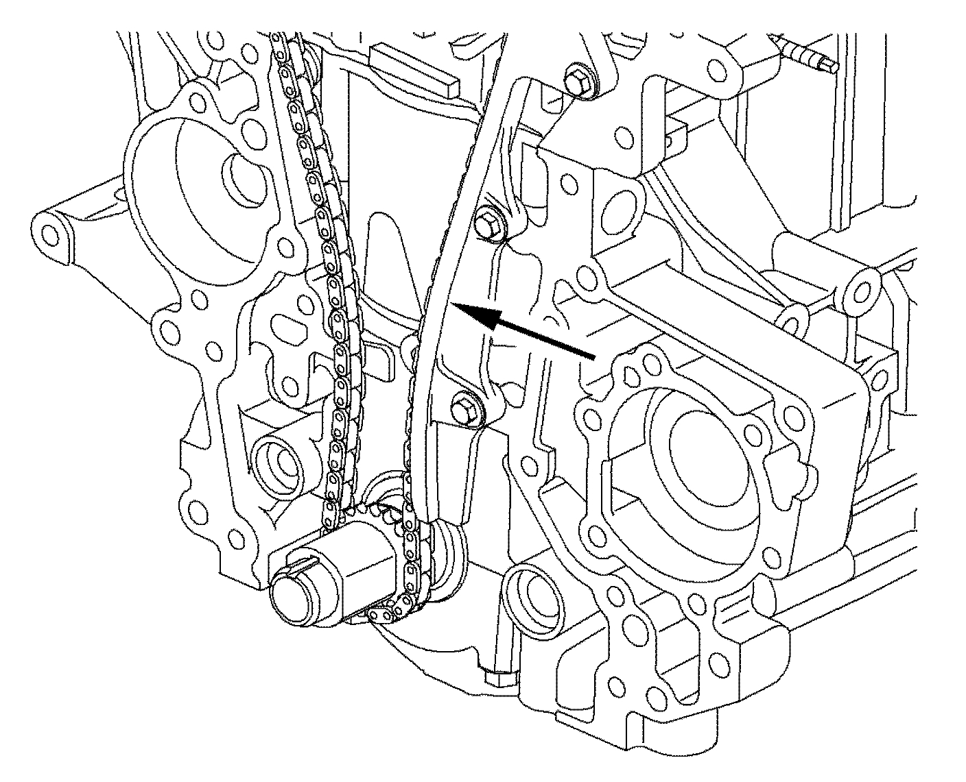
Important: The timing chain should be snug against the fixed guide.
7. Install the fixed guide.
Tighten
Tighten the timing chain fixed guide-to-block to 26 N.m (19 lb ft).
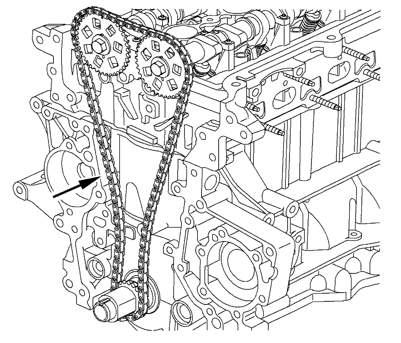
pic 41
8. Install the pivoting chain guide. Inspect for clearance between the block and the head. Torque the bolt and ensure the guide pivots freely.
Tighten
Tighten the timing chain pivot guide-to-head to 26 N.m (19 lb ft).
Important: The camshafts must be positioned fully forward prior to bearing cap installation.
9. Install the 2 forward remaining camshaft bearing caps and timing chain guide.
Tighten
Tighten the camshaft bearing cap-to-head (LL0) to 14 N.m (10 lbs ft).
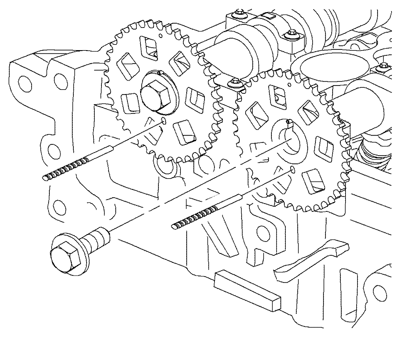
pic 42
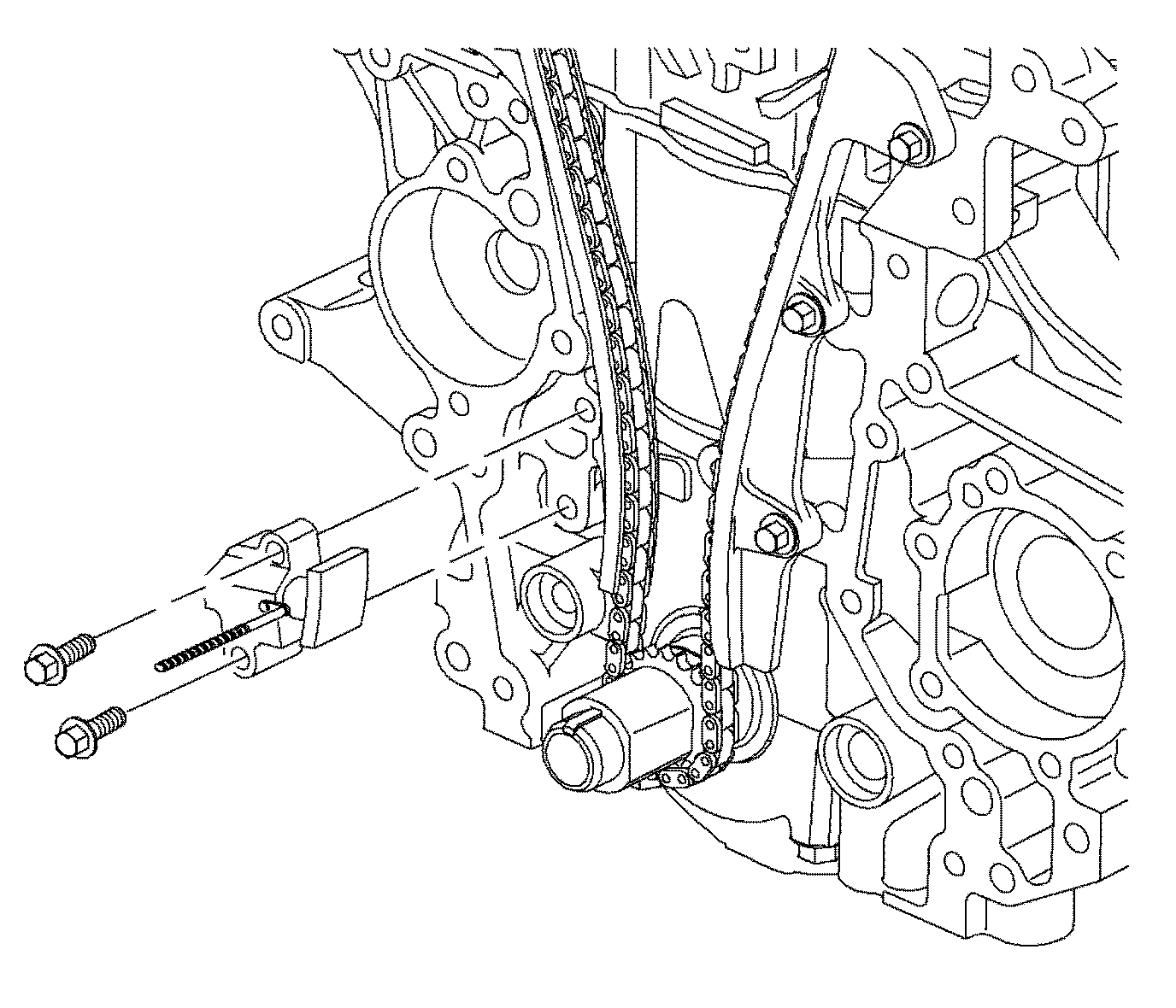
10. Retract the tensioner plunger and pin the ratchet lever using a 3.18 mm (1/8 in) or No 31 drill. Install the chain tension and torque the 2 bols. Remove the drill and allow the tensioner plunger to extend.
Tighten
Tighten the timing chain tensioner-to-block to 19 N.m (14 lb ft).
11. Verify all timing marks for accuracy. Remove the camshaft timing pins.
_________________________________
Let me know if this helps or if you have other questions.
Take care,
Joe
Images (Click to enlarge)
Sep 13, 2019 at 8:17 PM