Hi,
If it isn't aligned, you need to take it back apart. I'm sure that isn't what you want to hear. However, it need to be aligned. I suggest contacting a parts store to see if they have an alignment tool that they will rent or lend to you. I will provide all the directions for removal and replacement for you to help.
Here are the directions. The attached pics correlate with the directions.
__________________________________________________
2009 Pontiac Vibe FWD L4-1.8L
Clutch Assembly Replacement (MVE Manual Transmission)
Vehicle Transmission and Drivetrain Clutch Pressure Plate Service and Repair Removal and Replacement Clutch Assembly Replacement (MVE Manual Transmission)
CLUTCH ASSEMBLY REPLACEMENT (MVE MANUAL TRANSMISSION)
Clutch Assembly Replacement (MVE Manual Transmission)
Removal Procedure
pic 1
1. Remove the manual transaxle assembly. Refer to Transmission Replacement (See: Manual Transmission/Transaxle > Removal and Replacement > Transmission Replacement).
2. Remove the clutch release fork with the clutch release bearing from the manual transaxle.
pic 2
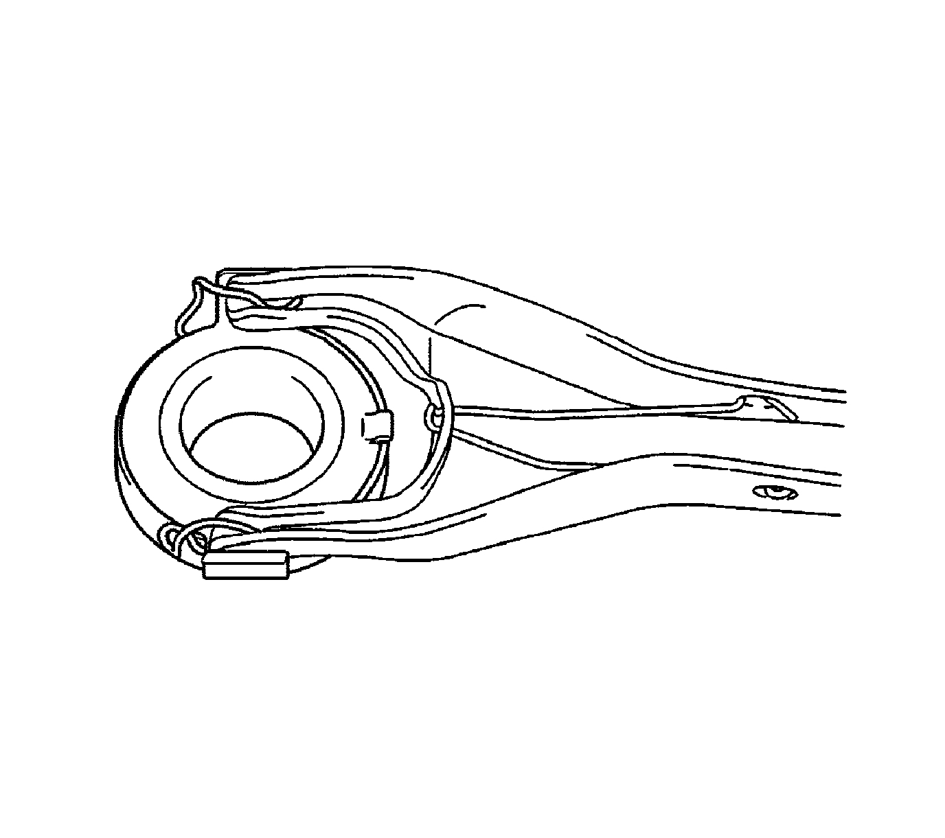
3. Remove the clutch release fork boot from the manual transaxle.
pic 3
4. Remove the release bearing and clip from the clutch release fork.
pic 4
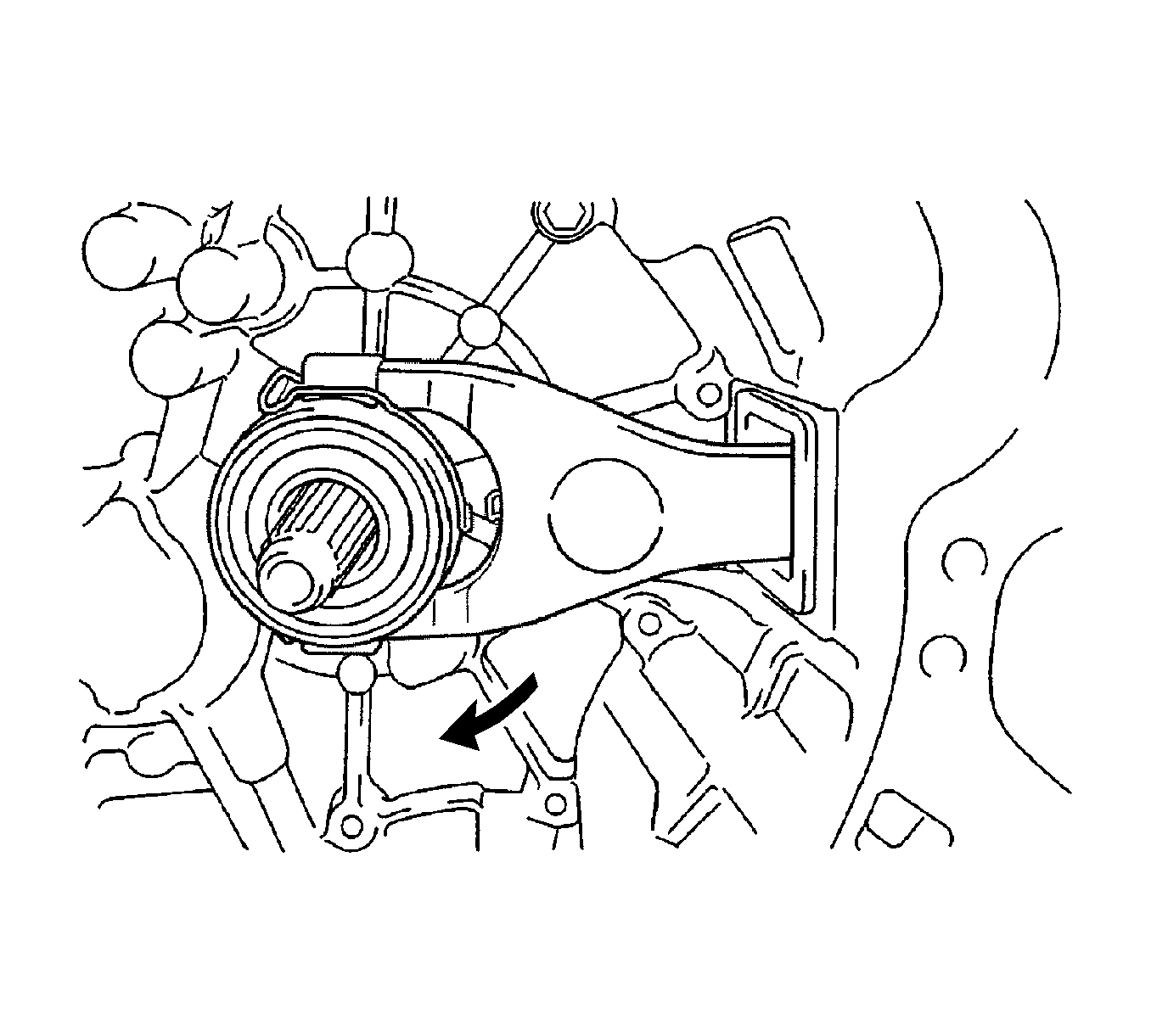
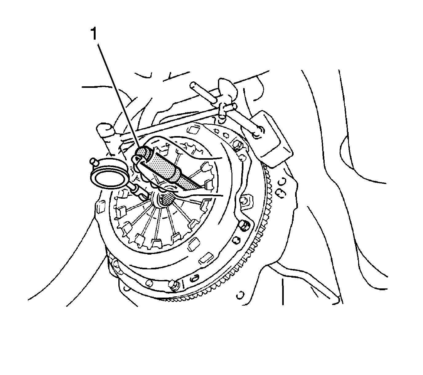
5. Remove the release fork support (1) from the manual transaxle.
pic 5
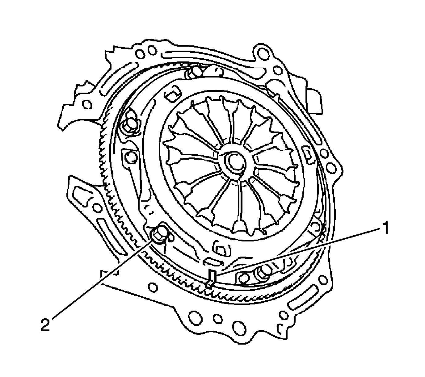
6. Put matchmarks (1) on the clutch cover assembly and the flywheel sub-assembly.
7. Loosen each bolt (2) one turn at a time until the spring tension is released.
8. Remove the bolts and pull off the clutch cover.
9. Remove the clutch disc assembly.
pic 6
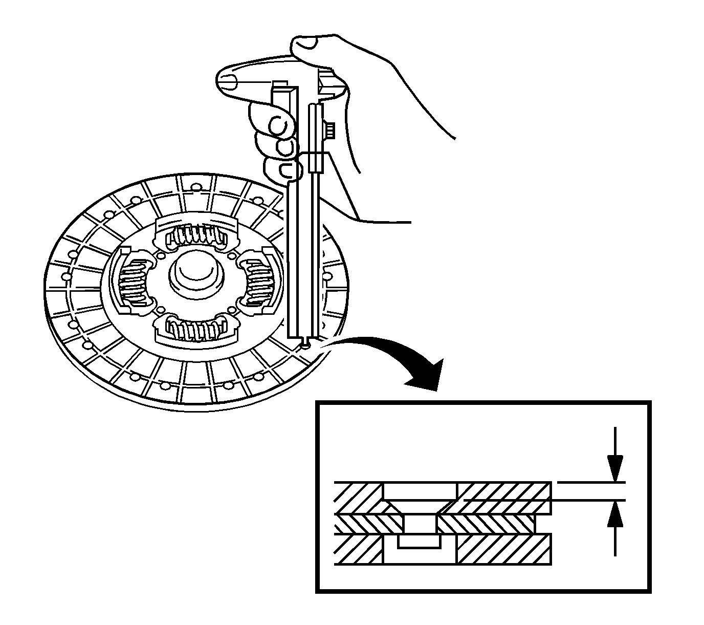
10. Using vernier calipers, measure the rivet head depth.
Minimum rivet depth: 0.3 mm (0.012 in)
If necessary, replace the clutch disc assembly.
Note: Insert the clutch disc assembly in the correct direction.
11. Install the clutch disc assembly onto the transaxle assembly.
pic 7
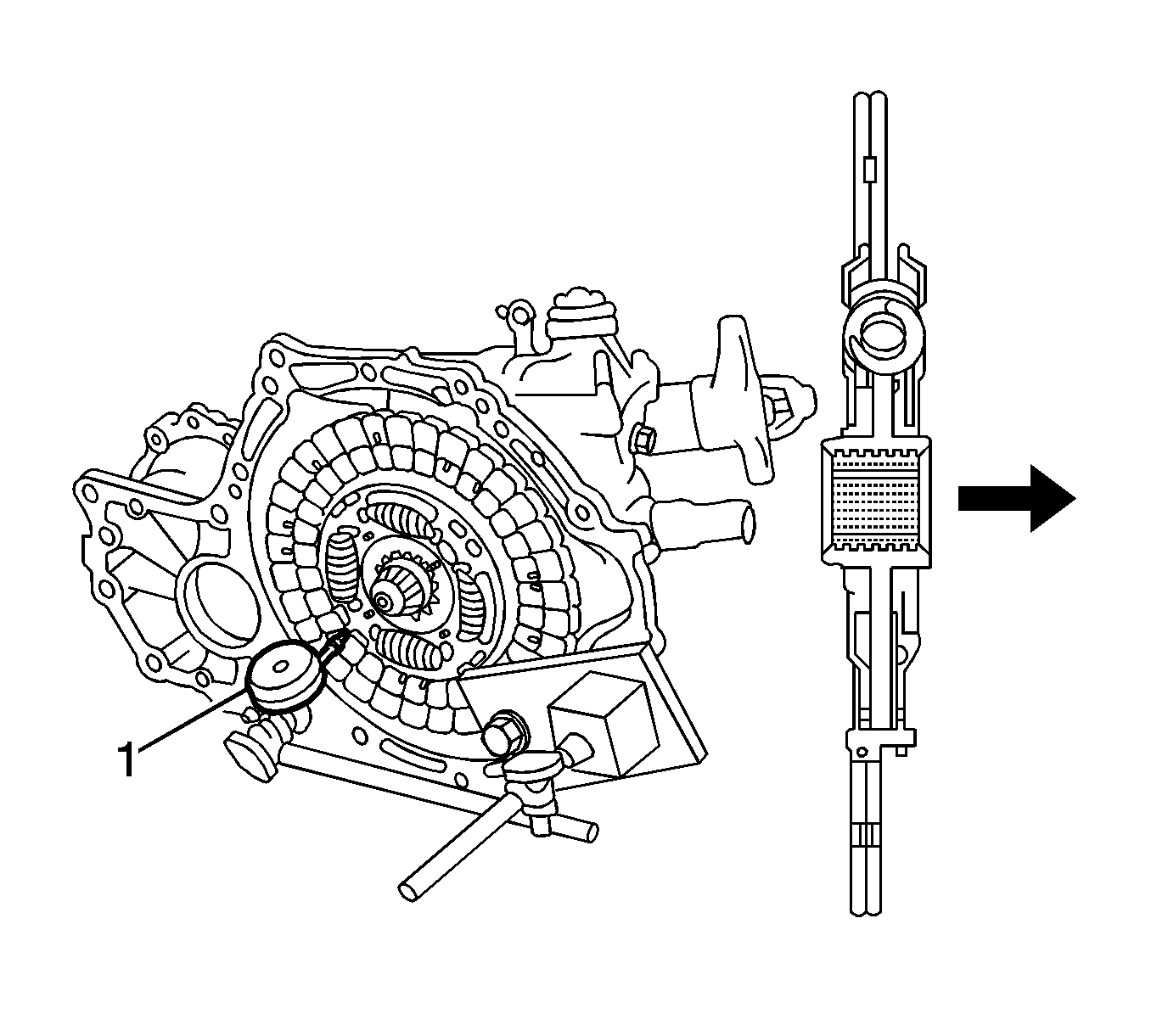
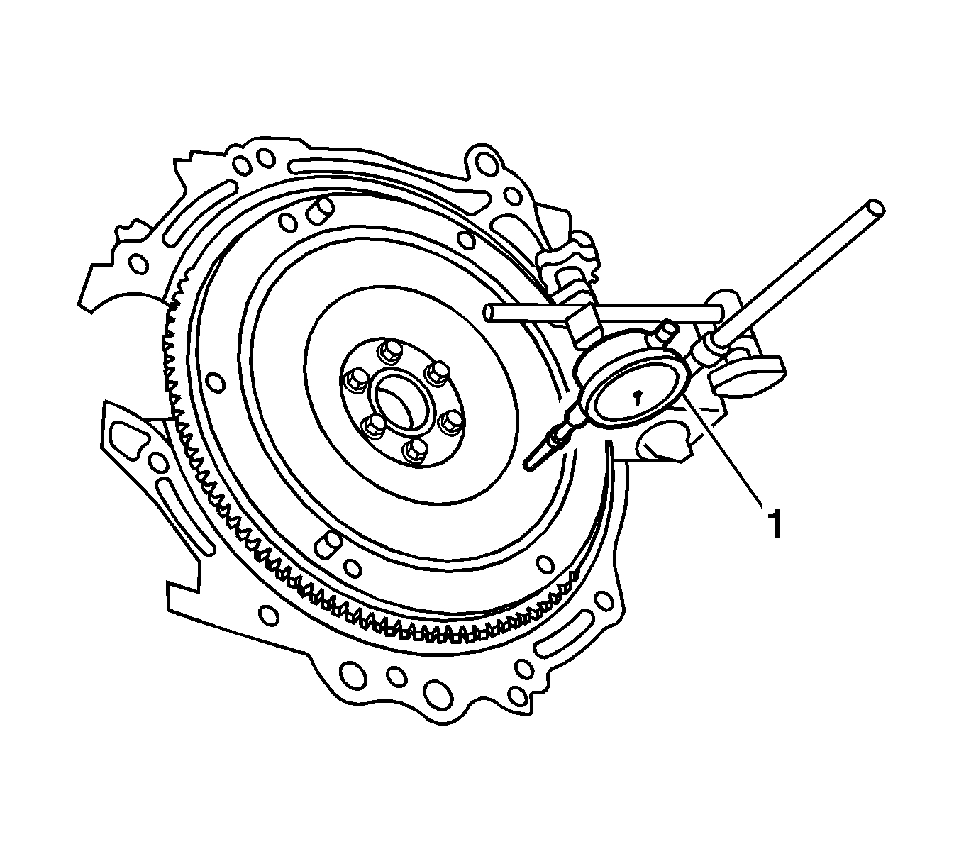
12. Using a dial indicator (1), measure the clutch disc assembly runout.
Maximum runout: 0.8 mm (0.031 in).
If necessary, replace the clutch disc assembly.
pic 8
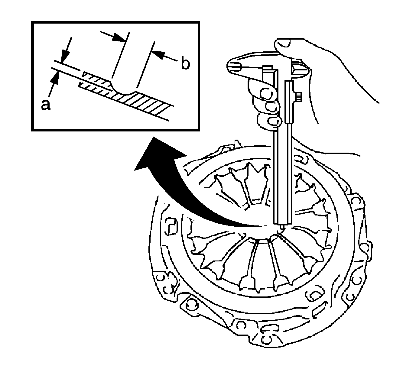
13. Using vernier calipers, measure the depth (a) and width (b) of the diaphragm spring wear.
If necessary, replace the clutch cover assembly.
pic 9
14. Using a dial indicator (1), measure the flywheel sub-assembly runout.
Maximum runout: 0.1 mm (0.004 in)
If necessary, replace the flywheel sub-assembly.
pic 10
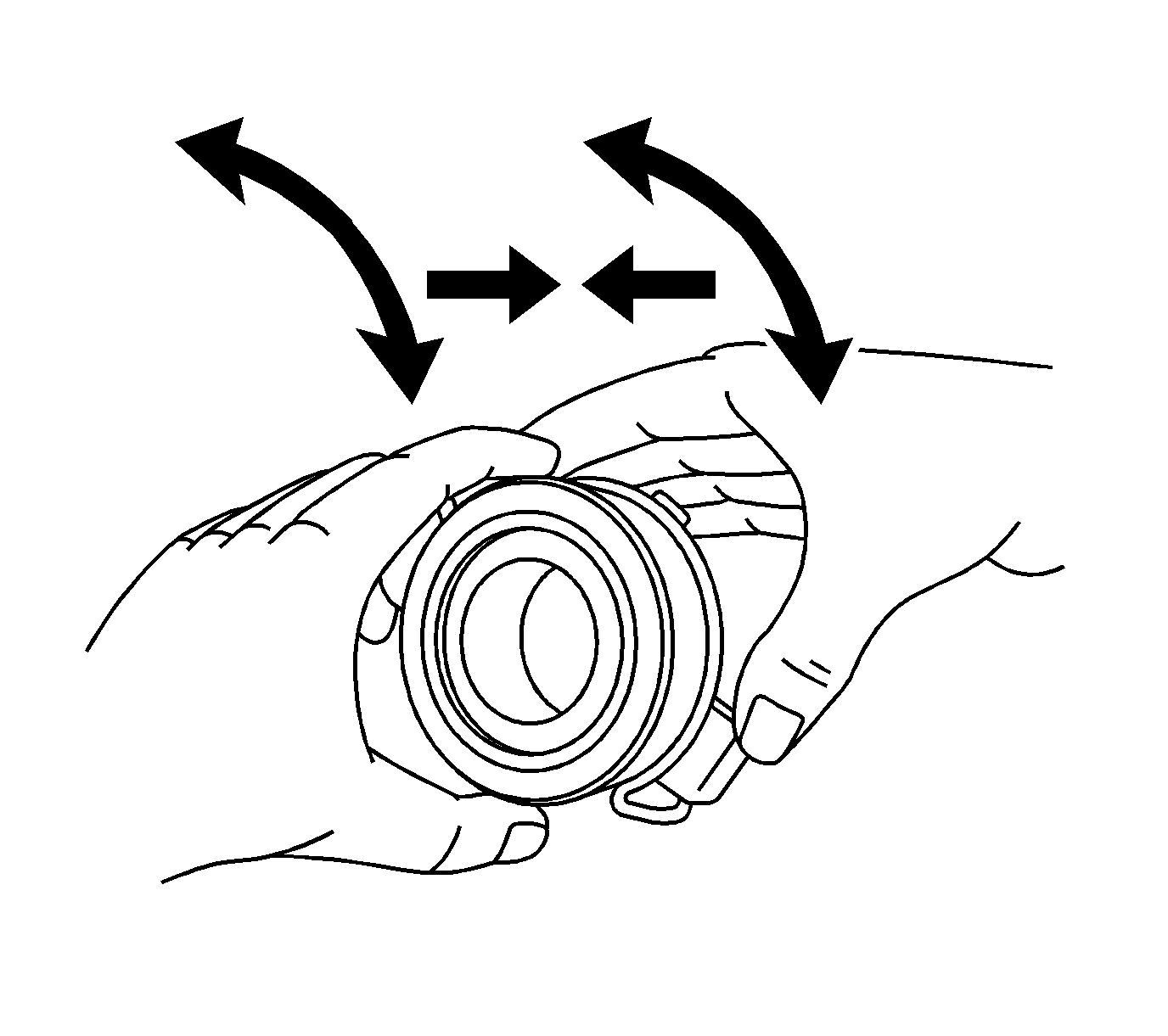
15. Check that the clutch release bearing assembly moves smoothly without abnormal resistance by turning the sliding parts of the clutch release bearing assembly-contact surfaces with the clutch cover-while applying force in the axial direction.
16. Inspect the clutch release bearing assembly for damage and wear.
If necessary, replace the release bearing assembly.
pic 11
Installation Procedure
pic 12
Note: Insert the clutch disc assembly in the correct direction.
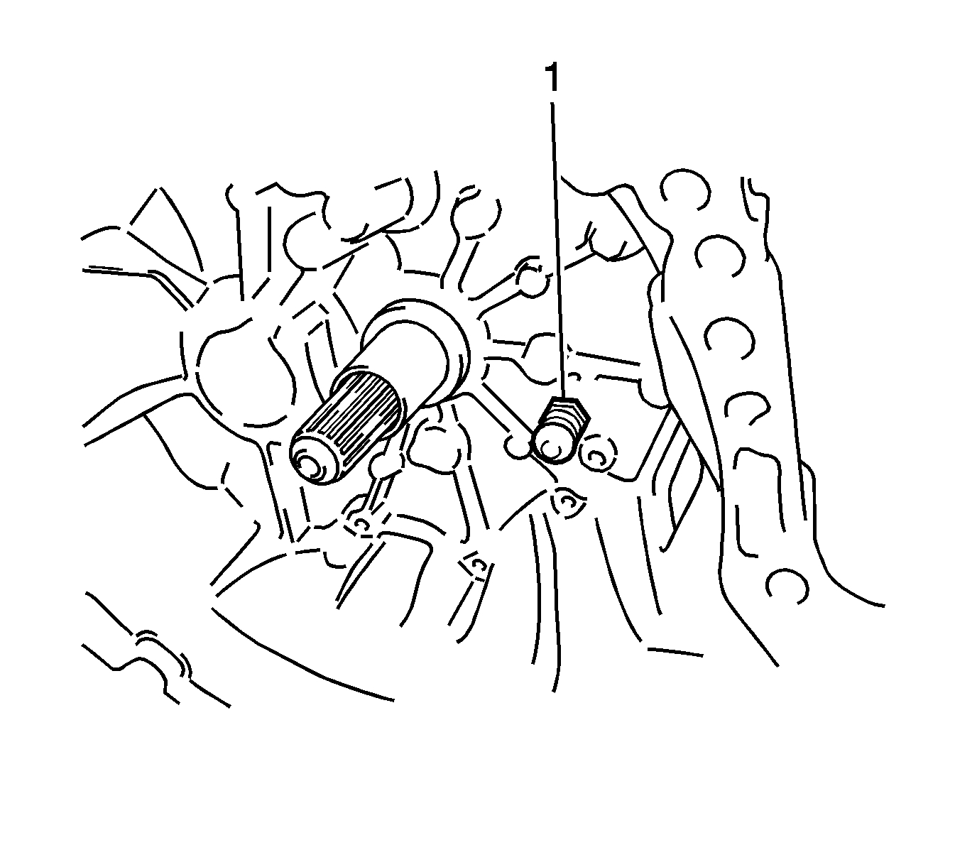
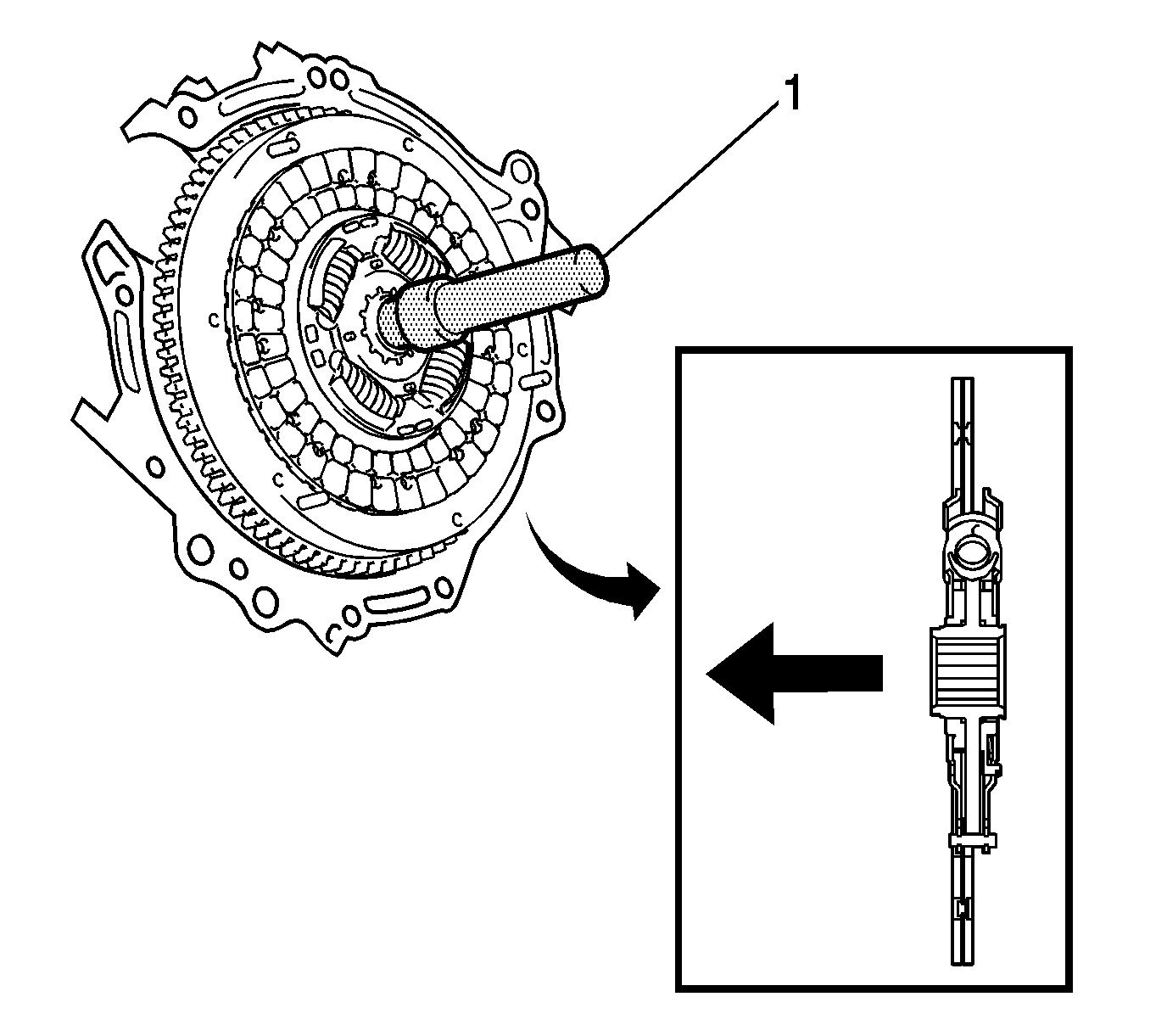
1. Insert a clutch pilot tool (1) into the clutch disc assembly, then insert them both into the flywheel sub-assembly.
pic 13
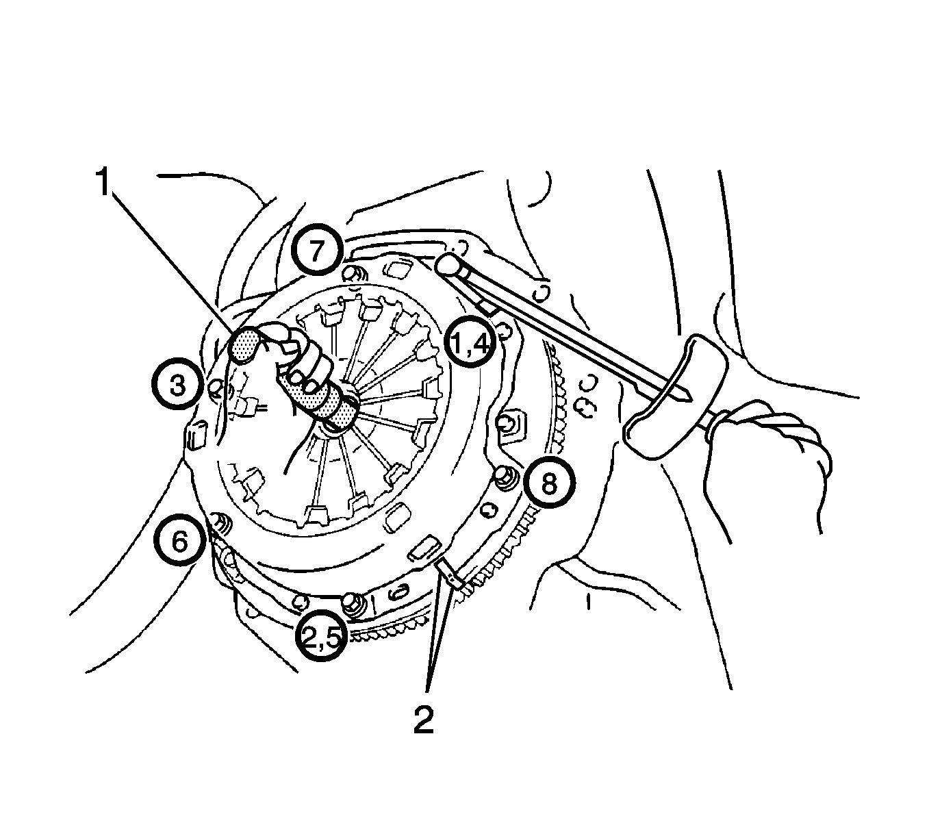
2. Align the matchmark (2) on the clutch cover assembly with the one on the flywheel sub-assembly.
Caution: Refer to Fastener Caution (See: Vehicle > Vehicle Damage Warnings > Fastener Caution).
Note:
* Tighten the bolts evenly one turn at a time.
* Move the pilot tool (1) up and down, right and left lightly after checking that the disc is in the center, and tighten the bolts.
3. Tighten the bolts in order, starting with the bolt located near the knock pin at the top to 19 Nm (14 lb ft).
pic 14
4. Using a dial indicator with a roller instrument (1), check the diaphragm spring tip alignment.
Maximum non-alignment: 0.9 mm (0.035 in)
5. If the alignment is not as specified, adjust the diaphragm spring tip alignment.
pic 15
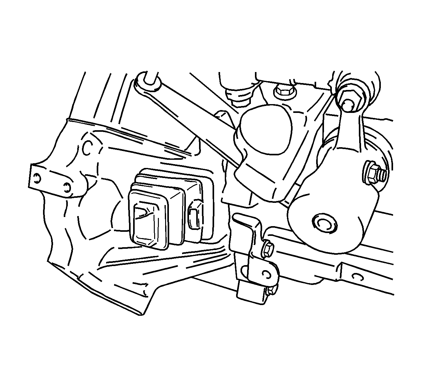
6. Install the release fork support (1) onto the transaxle assembly and tighten to 37 Nm (27 lb ft).
pic 16
7. Install the clutch release fork boot to the manual transaxle.
pic 17
8. Apply grease to the contact surfaces of the release fork, release bearing assembly, release fork push rod, and release fork support.
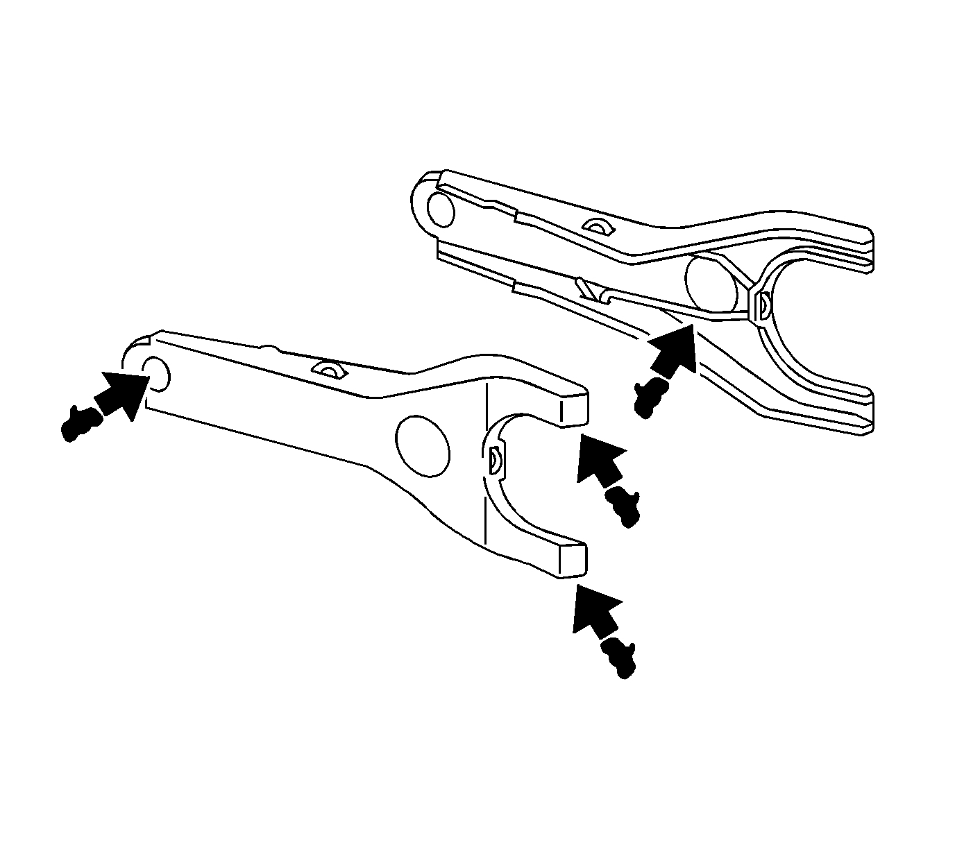
9. Install the release fork onto the release bearing assembly with the clip.
pic 18
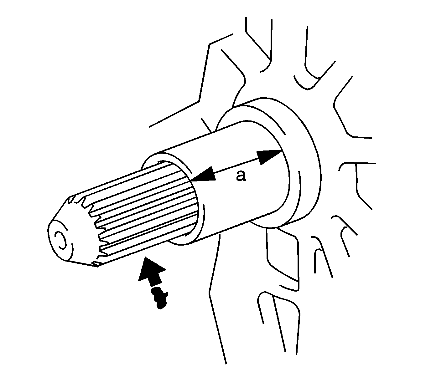
10. Apply grease to the input shaft spline.
11. Install the clutch release bearing with the release fork onto the transaxle assembly.
12. Install the manual transaxle assembly. Refer to Transmission Replacement (See: Manual Transmission/Transaxle > Removal and Replacement > Transmission Replacement).
________________________________________
Let me know if this helps. Also, compare the new parts to the ones being replaced. There were two different manual transmission around this time. One was a MVE and one was a MVC.
Let me know if this helps.
Joe
Images (Click to enlarge)
Jan 5, 2020 at 7:51 PM