Hello .. thanks for the donation .. much appreciated
You will need a shop with a good scan tester to do the following DTC test's .. I would start with these test's and checking the wiring/connectors before replacing the cluster
INSTRUMENT PANEL CLUSTER DIAGNOSTIC SYSTEM CHECK
NOTE:Use this check as the starting point for any instrument panel cluster complaint.
Testing
Install scan tool to DLC. If scan tool powers up, go to next step. If scan tool does not power up, see SELF-DIAGNOSTICS in appropriate BODY CONTROL MODULES article.
Turn ignition switch to ON position. Attempt to establish communications with the following modules:
Body Control Module (BCM)
Electronic Brake Control Module (EBCM)
Instrument Panel Cluster (IPC)
Powertrain Control Module (PCM)
Inflatable Restraint And Sensing Diagnostic Module (SDM)
If communication is established, go to next step. If communication cannot be established, go to SCAN TOOL DOES NOT COMMUNICATE WITH CLASS 2 DATA LINE under DIAGNOSTIC TESTS
Select scan tool display DTCs function for the following control modules:
Body Control Module (BCM)
Electronic Brake Control Module (EBCM)
Instrument Panel Cluster (IPC)
Powertrain Control Module (PCM)
Standard Diagnostic Module (SDM)
If scan tool displays any DTCs, go to next step. If scan tool does not display any DTCs, perform appropriate procedure under SYMPTOM TESTS .
If scan tool does not display any DTCs beginning with "U", go to next step. If scan tool displays any DTCs beginning with "U", go to SELF-DIAGNOSTICS in appropriate BODY CONTROL MODULES article.
If scan tool does not display DTC B1000, perform appropriate procedure under SYMPTOM TESTS . If scan tool displays DTC B1000, go to DIAGNOSTIC TESTS .
Diagnostic Aids
Following conditions may result in intermittent operation of instrument panel cluster with no DTC stored:
Any condition which results in interruption of power to instrument panel cluster.
Out of range battery or ignition voltage (normal instrument panel cluster operating voltage is 9-16 volts).
Loose or damaged ground(s).
Open or shorted serial data line.
Instrument panel cluster tests for different malfunctions during different vehicle conditions. A thorough test drive may be necessary to repeat malfunction. Most intermittent problems are caused by faulty electrical connections or wiring. Check for: poor connections, backed-out terminals, dirty or corroded terminals, chafed wires, or damaged connectors.
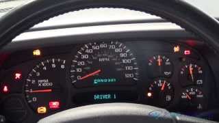
SPEEDOMETER GAUGE &/OR ODOMETER INOPERATIVE OR INACCURATE
If instrument panel cluster diagnostic check was performed, go to next step. If instrument panel cluster diagnostic check was not performed, go to INSTRUMENT PANEL CLUSTER DIAGNOSTIC SYSTEM CHECK .
Connect scan tool to DLC. Raise vehicle sufficiently for drive wheels to rotate. Start engine and place gear selector in DRIVE. Using scan tool, monitor VSS parameter in PCM ENGINE DATA 1 data list. If VSS parameter and speedometer display agree, go to next step. If VSS parameter and speedometer display do not agree, go to step 4 .
Road test vehicle to check speedometer/odometer operation. If system operates normally, problem is intermittent. Check for poor connections or damaged wires. See WIRING DIAGRAMS . Repair or replace if necessary. If speedometer/odometer do not operate normally, go to next step.
Replace IPC. See INSTRUMENT PANEL CLUSTER (IPC) under REMOVAL & INSTALLATION then go to next step.
Road test vehicle to check speedometer/odometer operation. If system operates normally, repair is complete. If problem still exists, return to step 2 .
Hope this helps

Sunday, July 18th, 2010 AT 4:25 AM