Hi,
It sounds like the crankshaft position sensor may have failed. Do me a favor and read through this link. Let me know if it mirrors what you experience.
https://www.2carpros.com/articles/symptoms-of-a-bad-crankshaft-sensor
If you have a live data scan tool, see if there is an RPM signal when cranking. If there is none, the chances are it is the sensor.
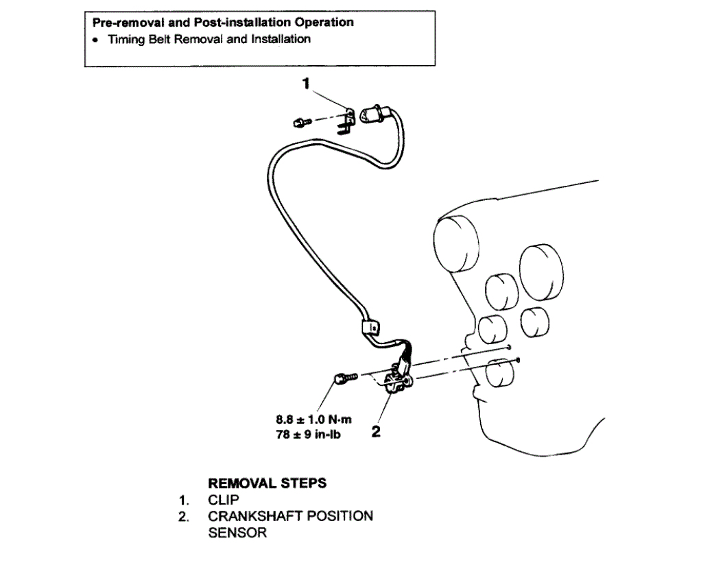
The bad thing is this. On this vehicle, you need to remove the timing belt to replace the sensor. If you look at the last pic below, you can see the sensor and all that holds it on. The directions for replacing it are in the pic.
If you identify this as the problem, here are the directions for the removal and replacement of the timing belt. This would also be a good time to replace it. The remaining pics correlate with the directions.
_________________________
2003 Mitsubishi Eclipse V6-3.0L SOHC
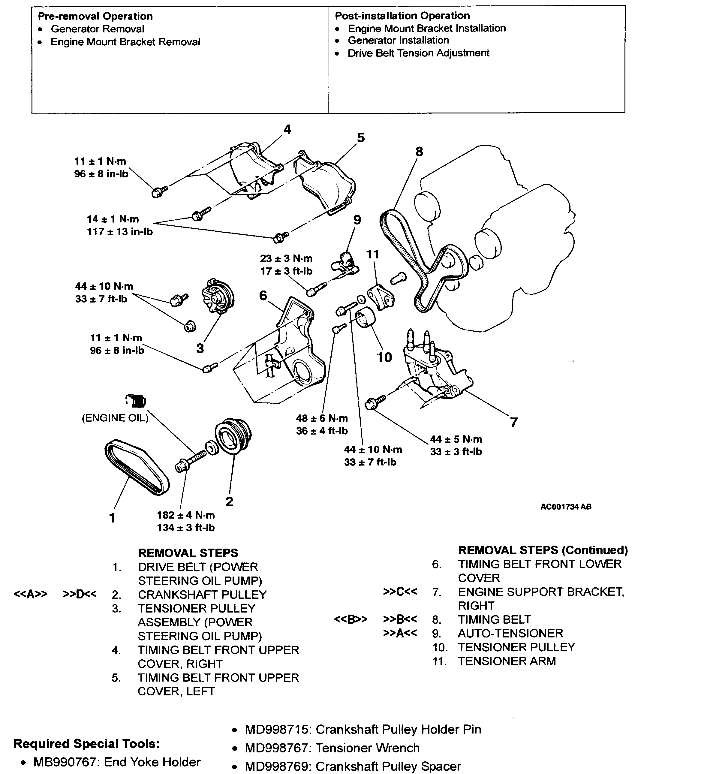
Removal and Replacement
Vehicle Engine, Cooling and Exhaust Engine Timing Components Timing Belt Service and Repair Removal and Replacement
REMOVAL AND REPLACEMENT
pic 1
pic 2
REMOVAL AND INSTALLATION
REMOVAL SERVICE POINTS
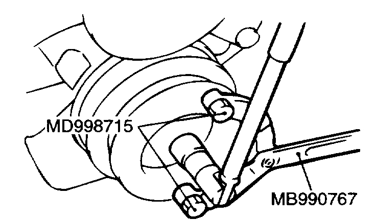
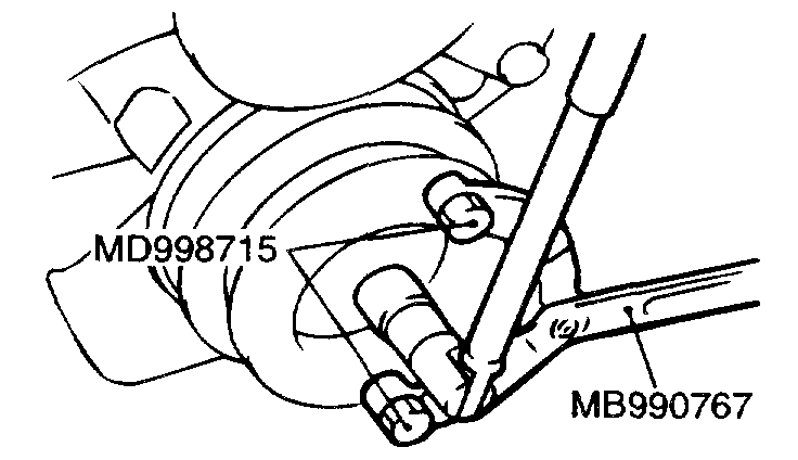
[[A]] CRANKSHAFT PULLEY REMOVAL
CAUTION: Use only the specified special tools, or a damaged pulley damper could result.
pic 3
Use special tools MB990767 and MD998715 to remove the crankshaft pulley from the crankshaft.
[[B]] TIMING BELT REMOVAL
CAUTION: Never turn the crankshaft counterclockwise.
pic 4
1. Turn the crankshaft clockwise to align each timing mark and to set the number 1 cylinder to compression top dead center.
2. If the timing belt is to be reused, chalk an arrow on the flat side of the belt, indicating the clockwise direction.
3. Loosen the center bolt of the tensioner pulley, then remove the timing belt.
INSTALLATION SERVICE POINTS
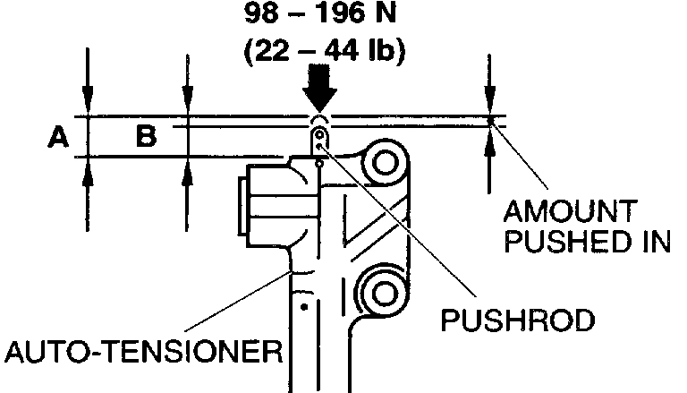
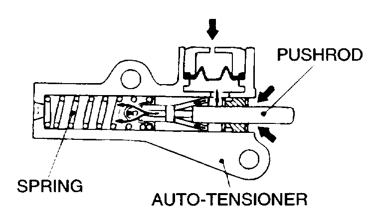
]]A[[ AUTO-TENSIONER INSTALLATION
pic 5
1. While holding the auto-tensioner with your hand, press the end of the pushrod against a metal surface (such as the cylinder block) with a force of 98 - 196 N (22 - 44 pound) and measure how far the pushrod is pushed in.
Standard value: Within 1 mm (0.04 inch)
A: Length when no force is applied
B: Length when force is applied
A - B: Amount pushed in
2. If it is not within the standard value range, replace the auto-tensioner.
CAUTION:
- Place the auto-tensioner perpendicular to the jaws of the vice.
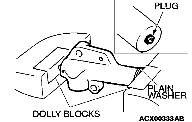
- If there is a plug at the base of the auto-tensioner, insert a plain washer onto the end of the auto-tensioner to protect the plug.
pic 6
3. Place two blocks in a vice as shown in the illustration, and then place the auto-tensioner in the vice.
CAUTION: Never compress the pushrod too fast, or it may be damaged.
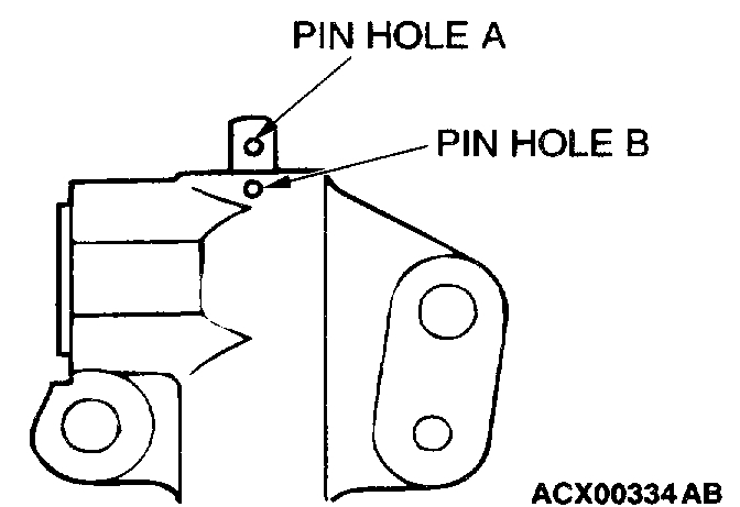
pic 7
4. Slowly compress the pushrod of the auto-tensioner until pin hole A in the pushrod is aligned with pin hole B in the cylinder.
5. Insert the setting pin into the pin holes once they are aligned.
NOTE: If replacing the auto-tensioner, the pin will already be inserted into the pin holes of the new part.
CAUTION: Do not remove the setting pin from the auto-tensioner.
6. Install the auto-tensioner to the engine.
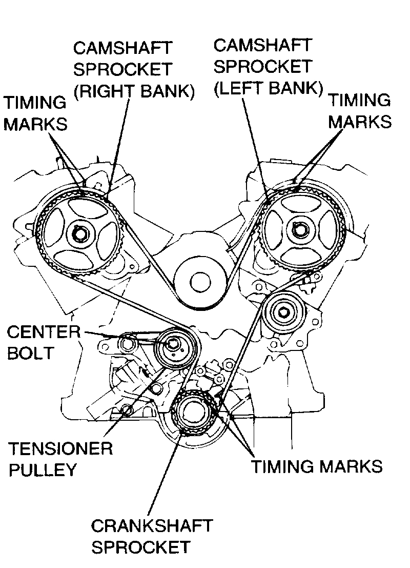
]]B[[ TIMING BELT INSTALLATION
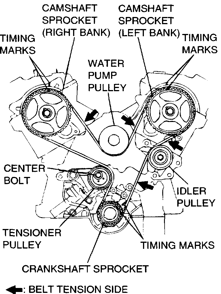
pic 8
1. Align the timing marks on the camshaft sprockets with those on the rocker cover and the timing mark on the crankshaft sprocket with that on the engine block as shown in the illustration.
CAUTION: The camshaft sprocket (right bank) can turn easily due to the spring force applied, so be careful not to get your fingers caught.
2. Install the timing belt by the following procedure so that there is no deflection in the timing belt between each sprocket and pulley.
1. Crankshaft sprocket
2. Idler pulley
3. Camshaft sprocket (Left bank)
4. Water pump pulley
5. Camshaft sprocket (Right bank)
6. Tensioner pulley
3. Turn the camshaft sprocket (Right bank) counterclockwise until the tension side of the timing belt is firmly stretched. Check all the timing marks again.
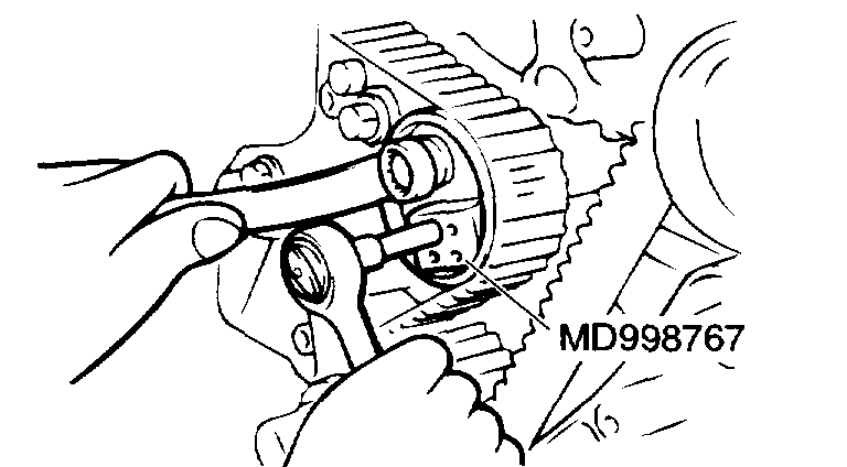
pic 9
4. Use special tool MD998767 to push the tensioner pulley into the timing belt, then temporarily tighten the center bolt.
pic 10
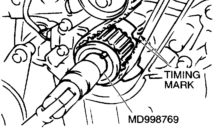
5. Use special tool MD998769 to turn the crankshaft 1/4 turn counterclockwise, then turn it again clockwise until the timing marks are aligned.
CAUTION: When tightening the center bolt, be careful that the tensioner pulley does not turn wig, the bolt.
pic 11
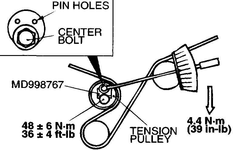
6. Loosen the center bolt of the tensioner pulley. Use special tool MD998767 and a torque wrench to apply the tension torque to the timing belt as shown in the illustration. Then tighten the center bolt to the specified torque.
Standard value: 4.4 Nm (39 inch lbs.) [Timing belt tension torque]
Tightening torque: 48 ± 6 Nm (36 ± 4 ft. lbs.)
7. Remove the setting pin that has been inserted into the auto-tensioner.
8. Turn the crankshaft clockwise twice to align the timing marks.
pic 12
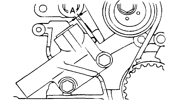
9. Wait for at least five minutes, then check that the auto-tensioner pushrod extends within the standard value range.
Standard value (A): 3.8 - 5.0 mm (0.15 - 0.20 inch)
10. If not, repeat the operation in steps (5) to (9).
11. Check again that the timing marks of the sprockets are aligned.
]]C[[ ENGINE SUPPORT BRACKET INSTALLATION
pic 13
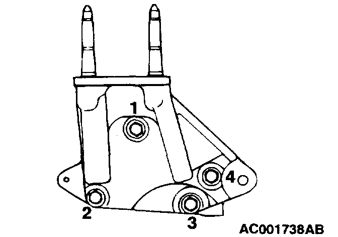
Tighten the right engine support bracket mounting bolts in the order shown in the illustration.
]]D[[ CRANKSHAFT PULLEY INSTALLATION
pic 14
Use special tools MB990767 and MD998715 to install the crankshaft pulley.
INSPECTION
AUTO-TENSIONER
pic 15
- Check the auto-tensioner for possible leaks.
- Check the pushrod for cracks.
_______________________
Let me know if this helps or if you have other questions.
Take care,
Joe
Images (Click to make bigger)
Saturday, October 31st, 2020 AT 6:36 PM