Hi and thanks for using 2CarPros.
There are two different components in questions here. First, the blend air door is what determines the air temperature entering the vehicle. The component itself is easy to replace, the hard part is getting to it. The next component in question is the mode door. This door directs air flow.
Now, the blend door is operated by an electric actuator, and the mode door is vacuum actuated. What I suggest is to check both for operation. If you find the mode door works, then there is an issue with low coolant or a plugged heater core.
With that in mind, first take a look through these links.
https://www.2carpros.com/articles/car-heater-not-working
https://www.2carpros.com/articles/air-vents-stay-in-the-defrost-position
Here is a link that shows in general how to replace a blend air door actuator.
https://www.2carpros.com/articles/replace-blend-door-motor
_____________________________________
Now, if you determine that these two components aren't working, here are the directions for replacement. First, I will give you the directions for each component, and last I will provide the process to access them.
____________________________________
Blend air door
Removal
1. Remove instrument panel assembly. Refer to Instrument Panel/Service and Repair. See: Instrument Cluster / Carrier > Procedures
2. Disconnect the electrical harness, to the temperature controller on the control assembly, from the blend door actuator.
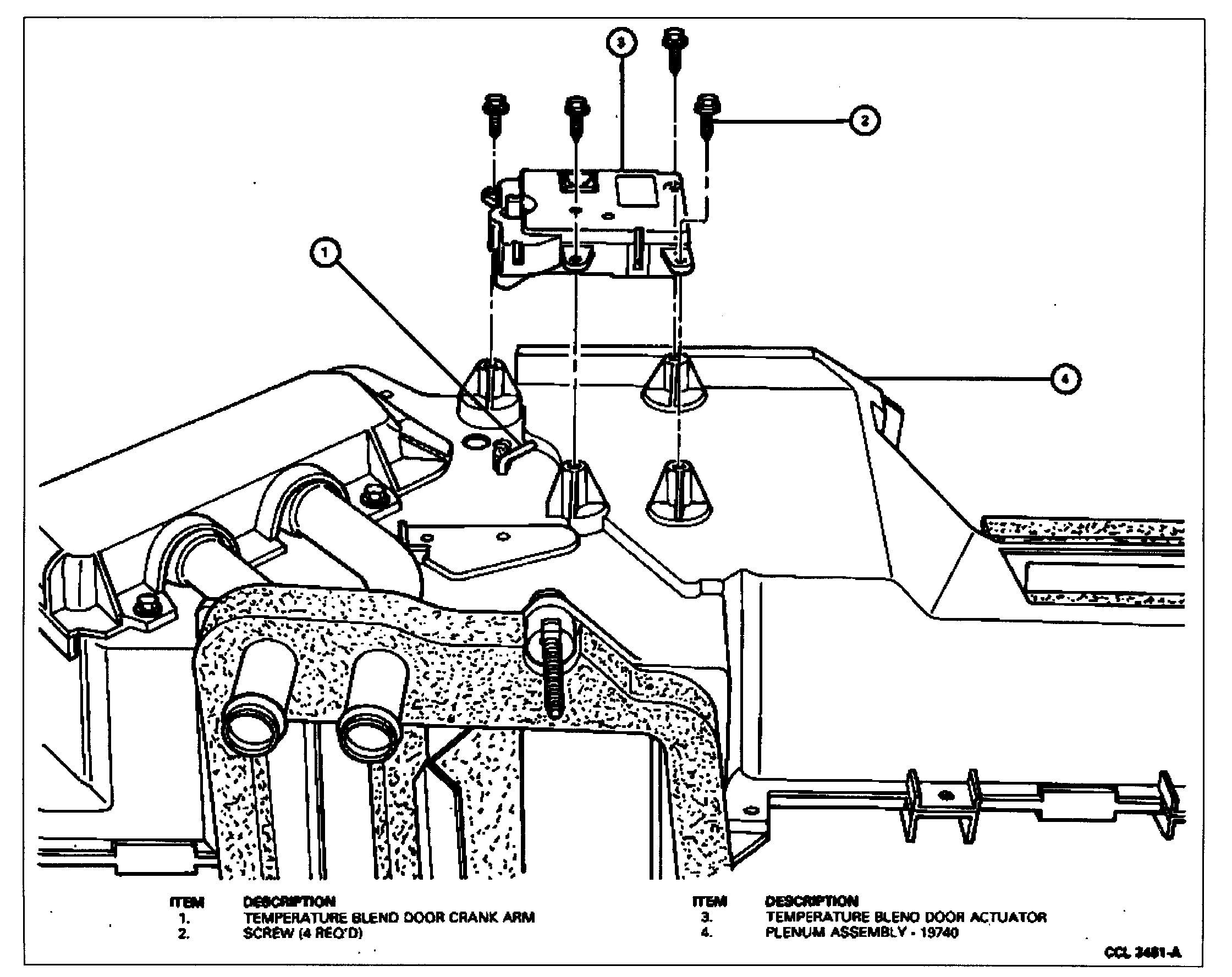
Temperature Blend Door Actuator
See picture 1
3. Remove four screws and remove the blend door actuator from the plenum assembly.
Installation
1. Position the blend door actuator on the plenum assembly. Be sure the actuator cam is properly engaged with the temperature blend door crankarm.
2. Install the four screws that secure the blend door actuator to the plenum assembly.
3. Connect the temperature controller electrical harness to the blend door actuator.
4. Install instrument panel. Refer to Instrument Panel/Service and Repair.
_______________________________________________
Here are the directions for the mode door. Note that it is vacuum actuated. The vacuum comes from the engine, so if there is a leak, it may not work. Often times, a leak will make a hissing sound when the engine is running, so pay attention for that.
FLOOR-DEFROST
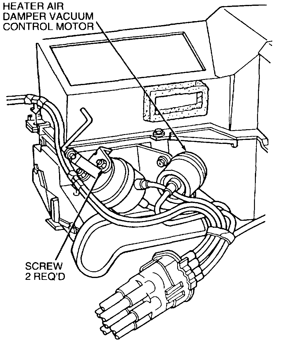
Motors, Vacuum Control
Windshield Defroster Door
See picture 2
Removal
1. Remove the heater outlet floor duct as outlined.
2. Remove the pushnut retaining the vacuum motor arm to the floor-defrost door crank arm.
3. Remove two nuts retaining the vacuum control motor to the motor bracket.
4. Disengage the vacuum control motor from the mounting bracket and the motor arm from the door crank arm.
5. Remove the vacuum control motor from the heater air plenum chamber. Disconnect the vacuum hoses from the vacuum control motor.
Installation
1. Connect the yellow vacuum hose to the vacuum motor end nipple and the red vacuum hose to the vacuum motor side nipple. Position vacuum control motor to the floor-defrost door crank arm and the motor mounting bracket.
2. Install two nuts to retain the vacuum control motor to the mounting bracket.
3. Install a new pushnut to retain vacuum control motor arm on the door crank arm.
4. Install the heater outlet floor duct assembly.
5. Check the system for proper operation.
Heater Air Damper Door
Removal
1. Remove the heater air plenum chamber from the vehicle as outlined.
2. Reach through the demister nozzle and duct opening and remove the sleeve nut attaching the vacuum motor arm to the heater air damper door.
3. Remove two screws attaching the vacuum control motor to the mounting bracket.
4. Disengage the vacuum control motor from the heater air plenum chamber and disconnect the vacuum hose from the vacuum control motor.
Installation
1. Position the vacuum control motor to the mounting bracket and the heater air damper door bracket.
2. Install two screws to attach the vacuum control motor to the mounting bracket.
3. Connect the vacuum motor arm to the heater air damper door with a new sleeve nut.
4. Connect the vacuum hose to the vacuum control motor.
5. Install the heater air plenum chamber in the vehicle as outlined.
6. Check the system for proper operation.
______________________________________________
If you suspect a vacuum leak, here is a link that shows how to find one.
https://www.2carpros.com/articles/how-to-use-an-engine-vacuum-gauge
Here are the directions for accessing the components:
____________________________________________
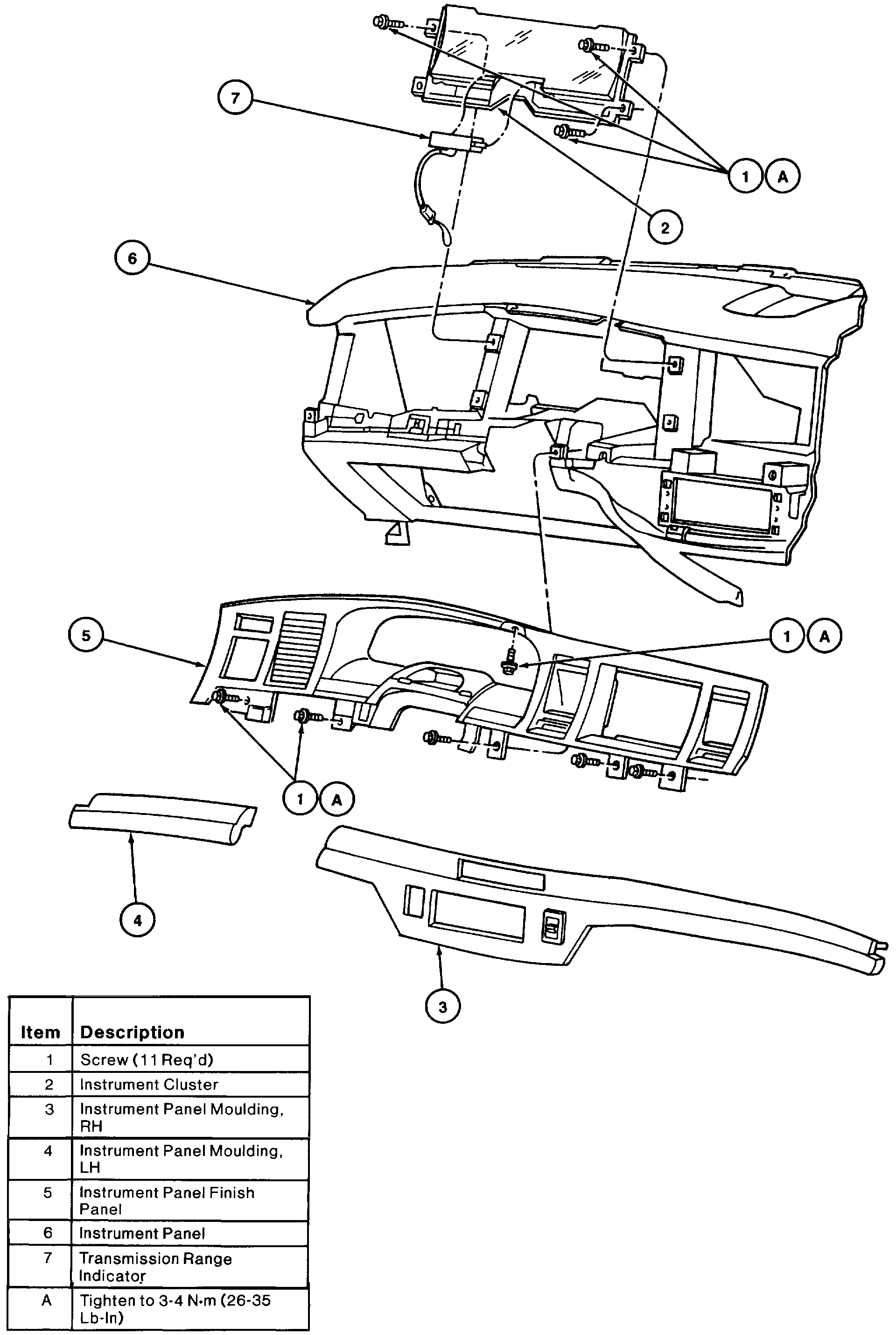
INSTRUMENT CLUSTER
See picture 3
NOTE: The electronics within the instrument cluster are NOT serviceable. For a confirmed electronic failure, return the entire assembly to the manufacturer (packaged carefully to avoid damage to the vacuum fluorescent displays and other electronic component)). Instrument cluster should be disassembled only to service plastic defects.
Federal law requires that the odometer in any replacement speedometer/odometer must register the same mileage as that registered on the removed speedometer/odometer. Service replacement speedometer/
odometers and odometer modules with the mileage preset to actual vehicle mileage are available through Ford Electronic Service Centers. In nearly all instances, the mileage continues to accumulate in the odometer memory even if the odometer does not display mileage. This mileage can usually be verified by the electronic service centers. Contact the service center for instructions to receive a replacement speedometer/odometer or odometer module with the mileage preset to actual mileage.
If the actual vehicle mileage cannot be verified, the service center will supply a speedometer/odometer or odometer module with the odometer display preset to zero ("0") miles and the service odometer segment ("5") illuminated in the vicinity of the odometer display. In addition, an odometer mileage sticker is supplied with the replacement odometer. This sticker must display the estimated vehicle mileage and is to be affixed to the driver door.
REMOVAL
1. Disconnect battery ground cable.
2. Set parking brake.
3. Unsnap LH instrument panel moulding and RH instrument panel moulding oft instrument panel finish panel .
4. Pull center panel switches (if equipped) forward, disconnect electrical connectors and remove the center switches.
5. Remove seven screws retaining instrument panel finish panel and pull instrument panel finish panel out.
6. Move gearshift lever to low gear (1) position if required for easier access.
7. Remove connectors from headlamp and dimmer controls.
8. Remove instrument panel finish panel carefully so as not to scratch the instrument cluster.
9. Disconnect electrical connector from front of instrument cluster.
10. Disconnect transmission range indicator from instrument cluster carefully. Bend bottom tab down and pull transmission range indicator forward.
11. Remove four screws retaining instrument cluster. Pull instrument cluster out and disconnect electrical connectors on rear of instrument cluster.
12. Remove instrument cluster.
INSTALLATION
1. Follow removal procedure in reverse order.
2. Tighten the instrument panel finish panel retaining screws to 3-4 N.m (26-35 lb-in).
__________________________________________________________________
Only remove what is needed to access the components.
Let me know if this helps or if you have other questions.
Take care,
Joe
Images (Click to enlarge)
Jan 18, 2019 at 7:24 PM