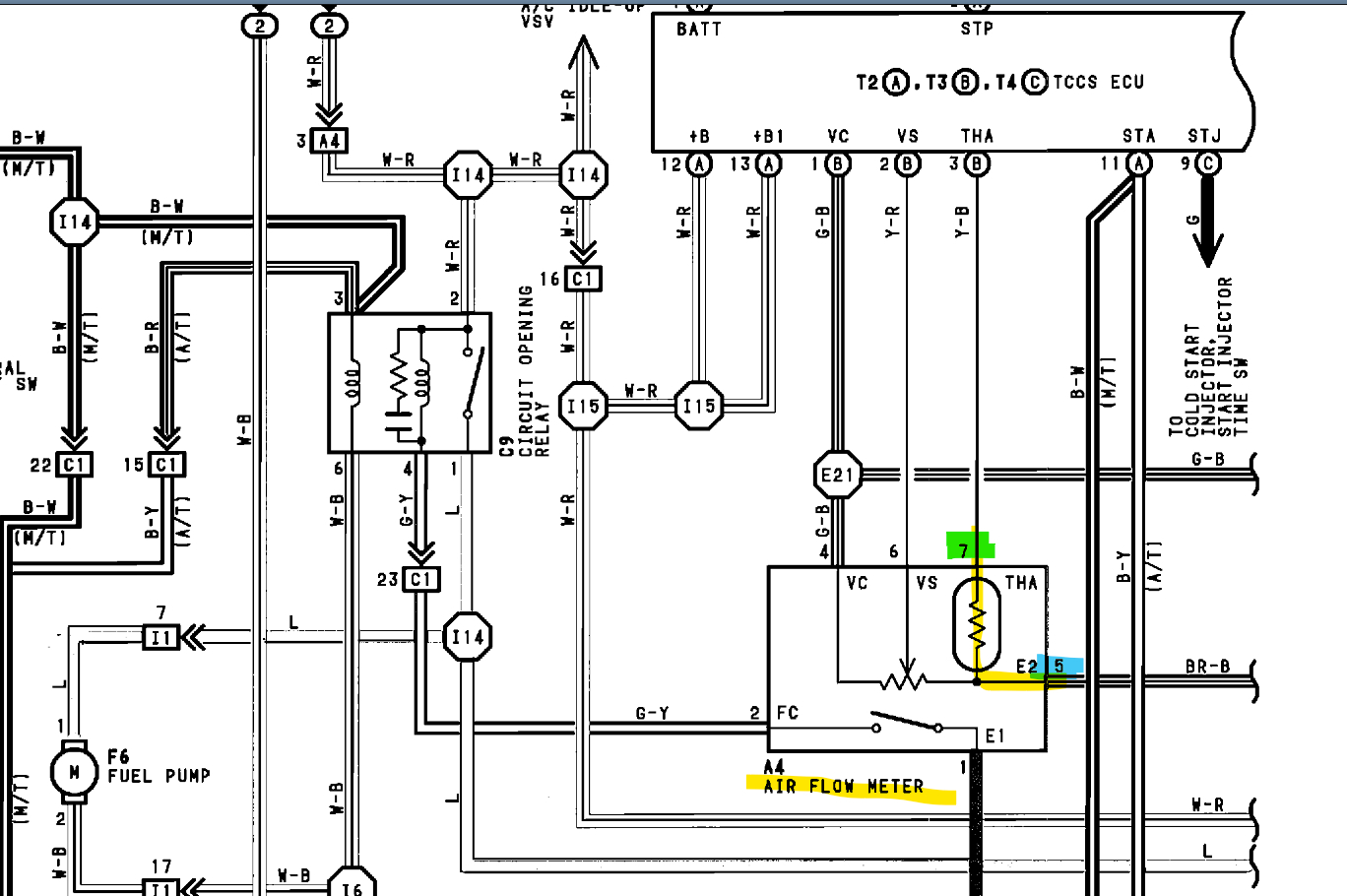
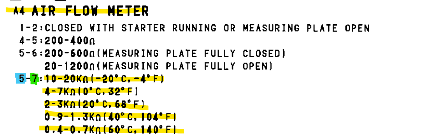
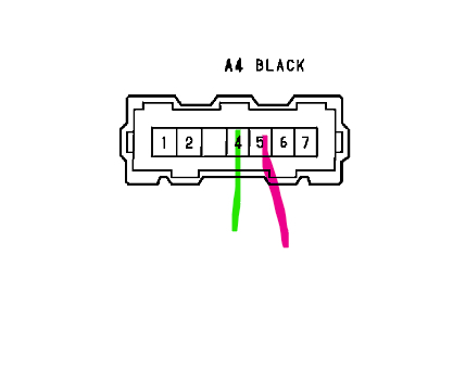
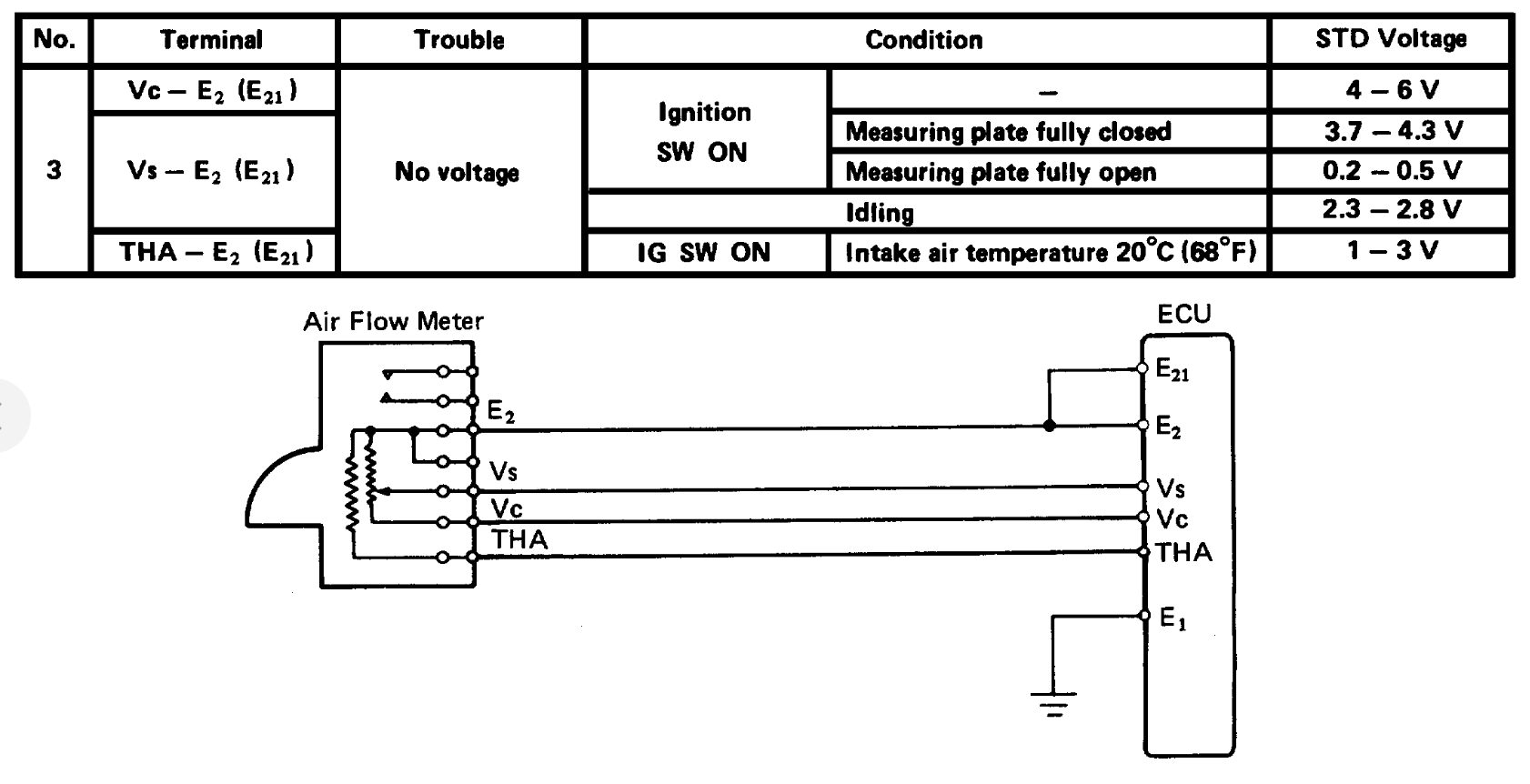
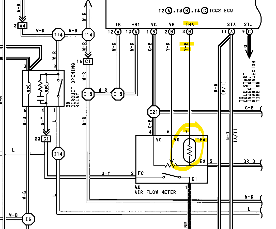
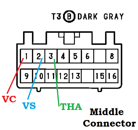
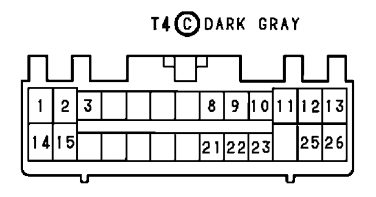
Okay, so you'll have to take some voltage readings next with the key on engine off. This isn't setup as a modern temperature sensor, for some reason they have the voltage feed for the temperature sensor running through another section of the air flow meter and then to the temperature sensor resistor and then out to the ECM. I'll post the connector diagram first, pin 4 (vc) should be a 4-6volt reading. Really, it's a 5-volt reference on modern vehicles. And pin 5 should be the sensor ground. So, with the connector unplugged and key on you should have 4-6 volts across pins 4 and 5, just touch the connector pins lightly so you don't spread the connector pins. That should read ok because you're not getting any air flow sensor codes. The next test looks like a plugged-in test, where you'll have to back probe the connector. I use T pins for this, just push them in following the wire straight into the back of the connector. Try not to damage the seal around the wire if there is one. But with it plugged in across pins 7(THA) and pin 5(E2) you should read 1 to 3 volts; I think you're not going to get a voltage reading here. If you do, they want you to back probe the computer connectors to see if it's a faulty ECM. This is the old design, so testing is different.
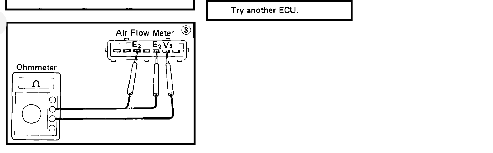
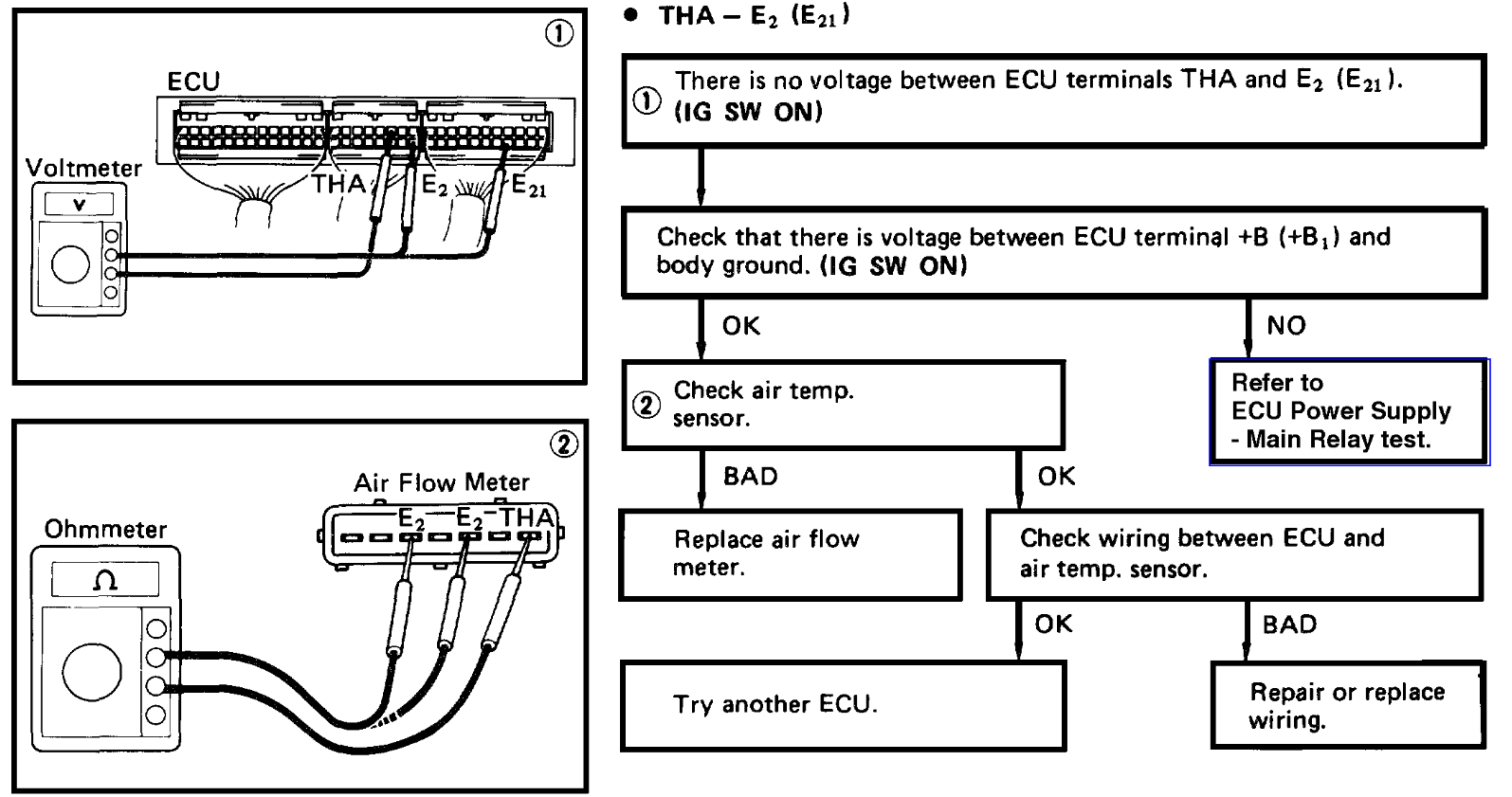
But the 2nd diagram shows how they wired the temperature sensor internal to the air flow meter. Where they have the incoming voltage (VC) going through the air flow meter (VS) and then going to the temperature sensor (THA), that's why the voltage reading will be lower (1-3volts) because it's going through another sensor first., Hopefully this is not a bad ECM, because looking at this closer, if there was an open circuit inside the air flow meter, you should be getting a code for that. I'm going to pull up the ECM diagrams to because it might need to be checked there as well.
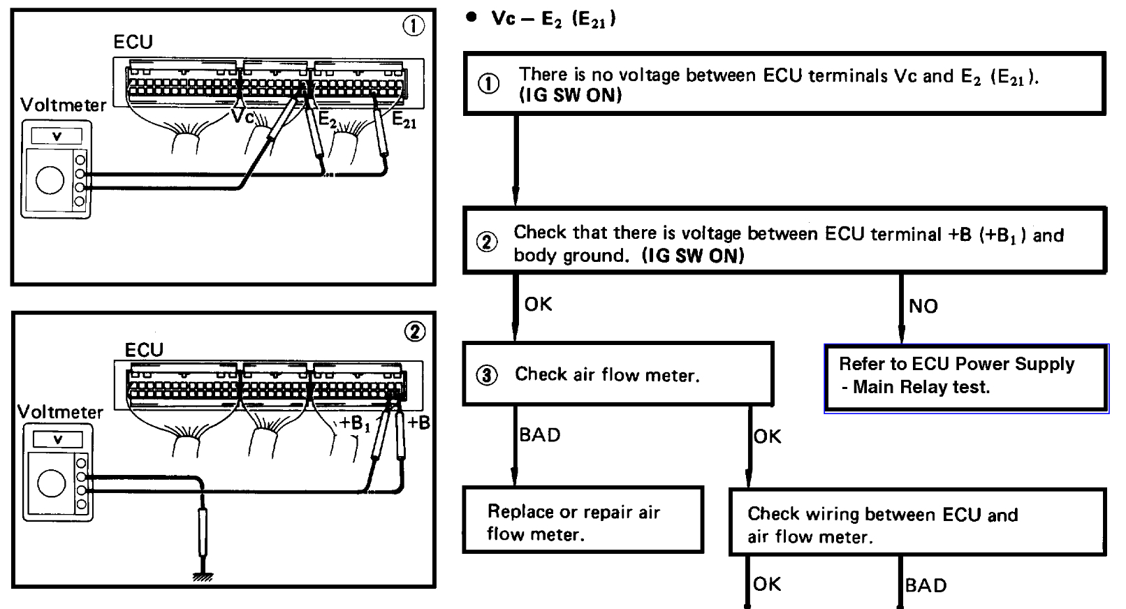
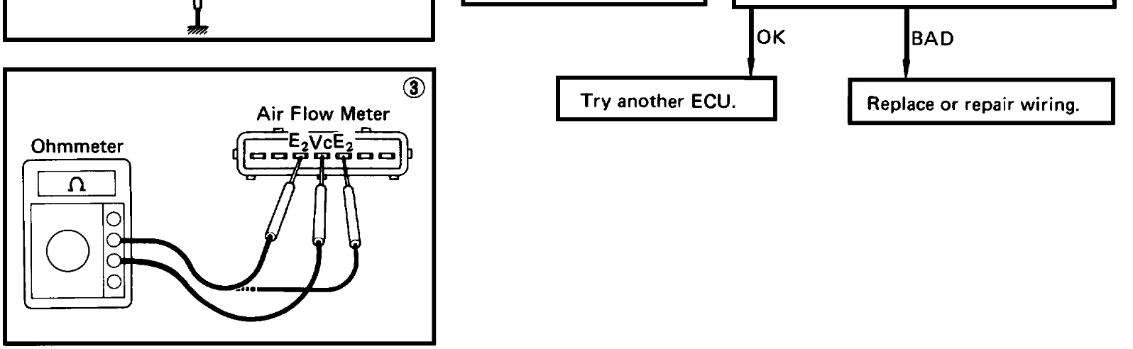
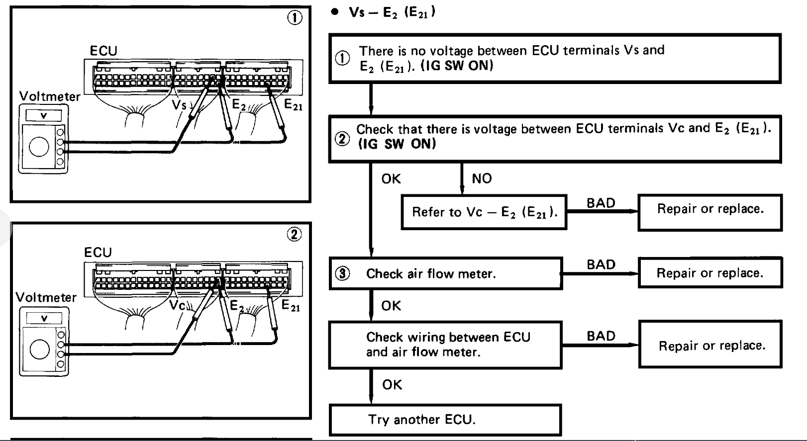
Diagrams 4 and 5 go together, 6 and 7 go together (top and bottom), and 8 is the last of the testing flow chart for the ECM. You can see what they want you to do for this sensor to determine if it's a wiring issue, bad sensor, or bad ECM.
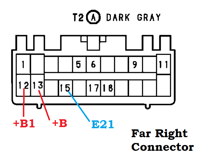
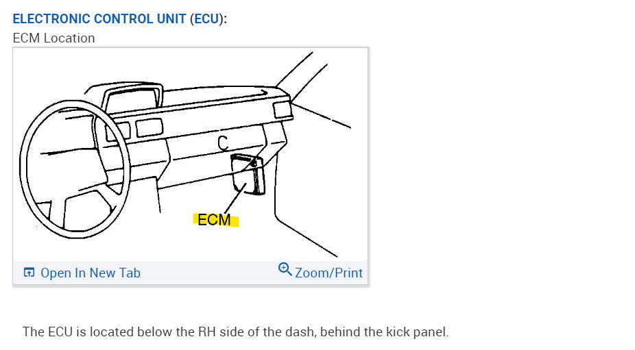
I've added the ECM connectors, they look backwards because they have them labelled as if you were looking at the connector, so on the flow chart they have you looking at the back of the ECM connectors for testing. Hope that is not too confusing. But each pin is marked for testing.
Images (Click to enlarge)
Mar 1, 2023 at 11:47 AM