Hi,
I'm not sure what you are asking. LH and RH indicates the sides of the engine. Each side has two cams, one for the exhaust and one for the intake.
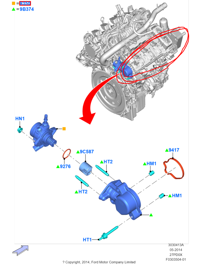
When you say high pressure fuel pump, the pump is mounted on the right side. If you are replacing a camshaft, I feel they should both be done at the same time. Also, it would be wise to inspect the opposite side to confirm there is no wear.
As far as replacing the cams, here are the directions. Note that it does mention the install of the high pressure drive assembly. The attached pics correlate with the directions.
__________________________________________
2017 Ford Truck F 150 2WD V6-2.7L Turbo
Camshaft RH
Vehicle Engine, Cooling and Exhaust Engine Camshaft, Lifters and Push Rods Camshaft Service and Repair Removal and Replacement Camshaft RH
CAMSHAFT RH
303-01A Engine - 2.7L EcoBoost (238kW/324PS) 2017 F-150
Removal and Installation
Camshaft RH
Special Tool(s) / General Equipment
Pic 1
Remover, Roller Rocker Follower
TKIT-2014D-ROW3
TKIT-2014D-FL_ROW
Materials
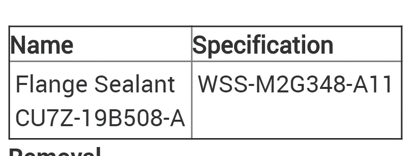
Pic 2
Name Specification
Flange Sealant
CU7Z-19B508-A WSS-M2G348-A11
Removal
NOTICE: During engine repair procedures, cleanliness is extremely important. Any foreign material, including any material created while cleaning gasket surfaces, that enters the oil passages, coolant passages or the oil pan, can cause engine failure.
NOTE: If the components are to be reinstalled, they must be installed in their original locations.
With the vehicle in NEUTRAL, position it on a hoist.
Refer to: Jacking and Lifting - Overview (100-02 Jacking and Lifting, Description and Operation).
Release the fuel system pressure.
Refer to: Fuel System Pressure Release (310-00A Fuel System - General Information - 2.7L EcoBoost (238kW/324PS), General Procedures).
Disconnect the battery ground cable.
Refer to: Battery Disconnect and Connect (414-01 Battery, Mounting and Cables - 2.7L EcoBoost (238kW/324PS)).
Remove the following items:
Refer to: Valve Cover RH (303-01A Engine - 2.7L EcoBoost (238kW/324PS), Removal and Installation).
Refer to: Valve Cover LH (303-01A Engine - 2.7L EcoBoost (238kW/324PS), Removal and Installation).
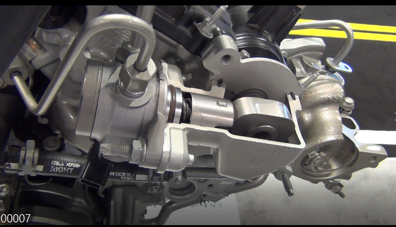
Refer to: High-Pressure Fuel Pump Drive Unit (303-04A Fuel Charging and Controls - 2.7L EcoBoost (238kW/324PS), Removal and Installation).
Remove the RH VCT units.
Refer to: Variable Camshaft Timing (VCT) Unit (303-01A Engine - 2.7L EcoBoost (238kW/324PS), Removal and Installation).
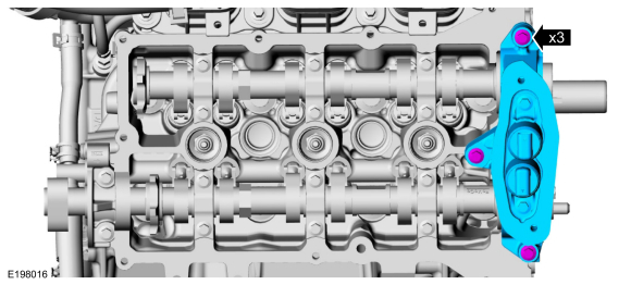
NOTICE: The front camshaft bearing mega cap must be removed first and then the remaining camshaft bearing caps. Failure to follow this direction may result in damage to the engine.
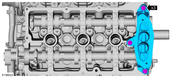
Remove the bolts and the front camshaft bearing mega cap.
Pic 3
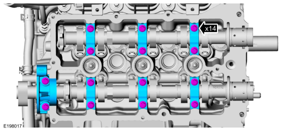
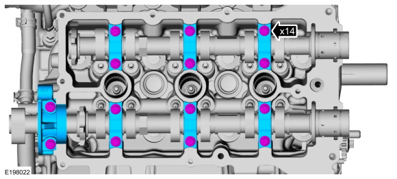
Remove the bolts and the camshaft bearing caps.
Pic 4
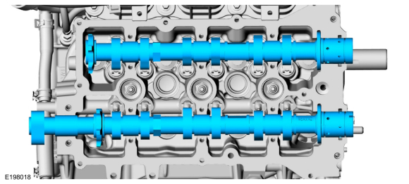
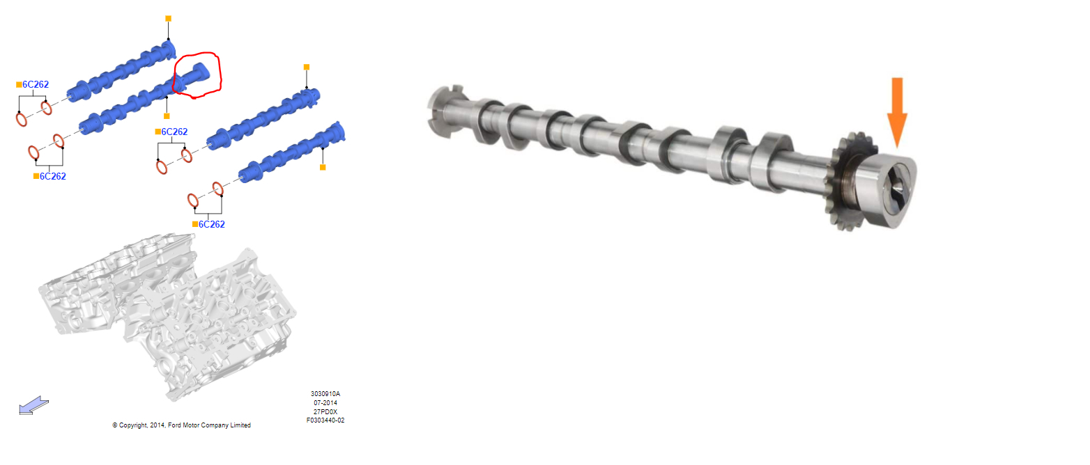
Remove the intake and exhaust camshafts.
Pic 5
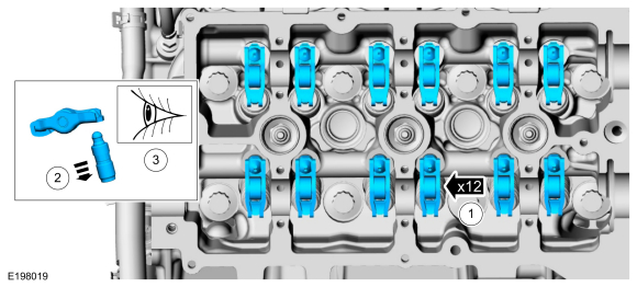
Remove the camshaft roller follower and hydraulic lash adjuster assemblies.
Separate the hydraulic lash adjusters from the spring clips on the camshaft roller followers.
Inspect the hydraulic lash adjuster and roller follower for damage. If any damage is found, inspect the camshaft lobes and valves for damage. Replace damaged components as necessary.
Pic 6
Installation
NOTICE: Do not install the camshaft roller followers at this time. The roller followers will be installed later in the procedure.
NOTE: If the original components are to be reinstalled, they must be installed in their original locations.
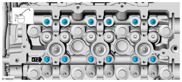
Lubricate the hydraulic lash adjusters with clean engine oil.
Install the hydraulic lash adjusters.
Pic 7
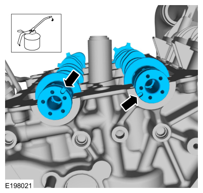
NOTE: Lubricate the camshafts with clean engine oil prior to installation.
NOTE: It is not necessary to position the scarf-cut seal ends when installing the camshafts.
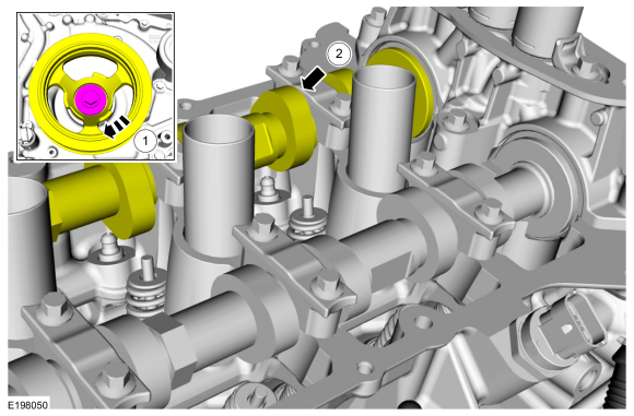
Install the intake and exhaust camshafts in the neutral position. Align the D-slots as shown in the illustration.
Pic 8
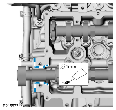
Apply a 1 mm bead of sealant to the rear camshaft cap mounting surface of the cylinder head.
Material : Flange Sealant / CU7Z-19B508-A (WSS-M2G348-A11)
pic 9
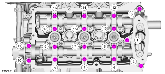
Install the camshaft bearing caps and the bolts. Do not tighten at this time.
Pic 10
Install the front camshaft bearing mega cap and the bolts. Do not tighten at this time.
Pic 11
Tighten the bolts.
Torque : 89 lb. In (10 Nm)
pic 12
Install the RH VCT units.
Refer to: Variable Camshaft Timing (VCT) Unit (303-01A Engine - 2.7L EcoBoost (238kW/324PS), Removal and Installation).
Rotate the crankshaft pulley bolt clockwise to position the camshaft lobe upward for the camshaft roller follower to be installed.
Pic 13
NOTE: Do not allow the valve keepers to fall off the valve or the valve may drop into the cylinder. If a valve drops into the cylinder, the cylinder head must be removed.
NOTE: It may be necessary to push the valve down while compressing the spring.
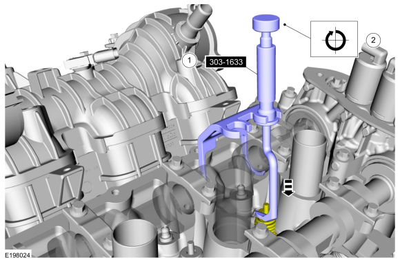
Install Special Service Tool: 303-1633 Remover, Roller Rocker Follower.
Turn the knob on the special tool clockwise to depress the valve and spring.
Pic 14
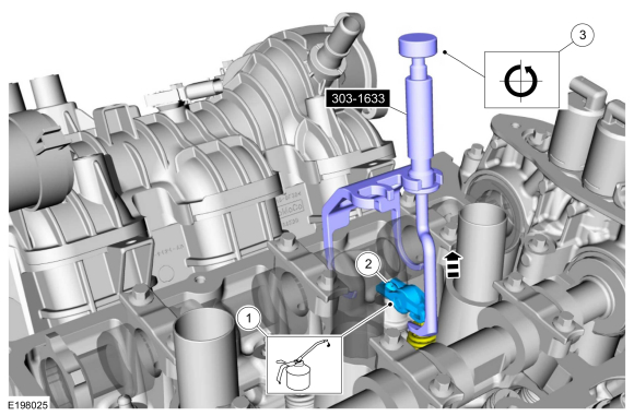
Lubricate the camshaft roller follower with clean engine oil.
Install the camshaft roller follower.
Turn the knob on the special tool counterclockwise to raise the valve and spring.
Remove Special Service Tool: 303-1633 Remover, Roller Rocker Follower.
Repeat steps for the remaining camshaft roller followers.
Pic 15
Install the following items:
Refer to: High-Pressure Fuel Pump Drive Unit (303-04A Fuel Charging and Controls - 2.7L EcoBoost (238kW/324PS), Removal and Installation).
Refer to: Valve Cover LH (303-01A Engine - 2.7L EcoBoost (238kW/324PS), Removal and Installation).
Refer to: Valve Cover RH (303-01A Engine - 2.7L EcoBoost (238kW/324PS), Removal and Installation).
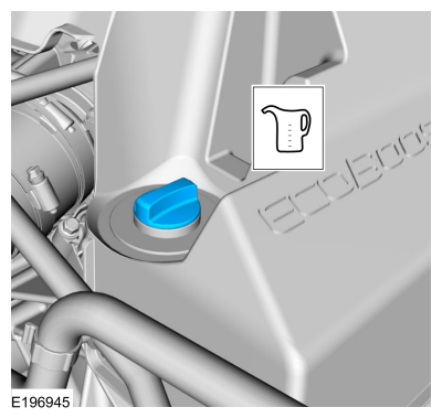
Fill the engine with clean engine oil.
Refer to: Specifications (303-01A Engine - 2.7L EcoBoost (238kW/324PS), Specifications).
Pic 16
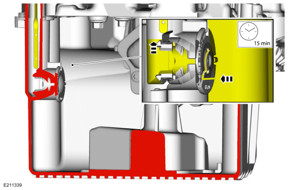
After filling the engine with oil, the oil must flow from the main chamber of the oil pan, through a check valve into the smaller side chamber to correctly register the oil level on the oil level indicator. This may take up to 15 minutes.
Pic 17
Connect the battery ground cable.
Refer to: Battery Disconnect and Connect (414-01 Battery, Mounting and Cables - 2.7L EcoBoost (238kW/324PS)).
Use the Powertrain Control Module (PCM) Misfire Monitor Profile Correction routine in the diagnostic scan tool.
__________________________
I'm not sure why the manual isn't being specific to which of the two drives it. I suspect they think the tech will see which it is once the valve cover is off.
Let me know if this helps.
Take care,
Joe
Images (Click to make bigger)
Wednesday, October 21st, 2020 AT 5:59 PM